SKF TIH L User manual

Instructions for use
Mode d’emploi
Bedienungsanleitung
Instrucciones de uso
Manuale d’istruzioni
Instruções de uso
使用说明书
Инструкция по эксплуатации
Betjeningsvejledning
SKF TIH L


English
English 2
Français
Français 16
Deutsch
Deutsch 29
Español
Español 42
Italiano
Italiano 56
Português
Português 70
中文
中文84
Русский
Русский 97
Dansk
Dansk 111

2SKF TIH L
Figure 1: TIH L as delivered
Figure 3: TIH L with open yoke
Figure 2: TIH L after bearing supports
assembly
Figure 4: TIH L with vertical workpiece
heating
Figure 5: TIH L with horizontal workpiece
heating

3SKF TIH L
Original instructions
EC Declaration of conformity ....................................................................................4
Safety recommendations ..........................................................................................5
1. Introduction .....................................................................................................6
1.1 Intended use ................................................................................................................... 6
1.2 Principle of operation .................................................................................................... 6
1.3 Distinguishing features ................................................................................................. 7
2. Description .......................................................................................................7
2.1 Components ................................................................................................................... 7
2.2 Technical data ................................................................................................................. 8
3. Installation of mains plug .................................................................................9
4. Preparation for use ........................................................................................10
5. Operation ......................................................................................................11
5.1 Function of displays .....................................................................................................11
5.2 Function of buttons .....................................................................................................11
5.3 TEMP MODE.................................................................................................................11
5.4 TIME MODE ..................................................................................................................12
5.5 Temperature measurement .......................................................................................12
5.6 Change of temperature unit .......................................................................................12
5.7 Demagnetisation ..........................................................................................................13
5.8 Power level selection ...................................................................................................13
6. Safety features ...............................................................................................13
7. Troubleshooting ..............................................................................................14
8. Spare parts ....................................................................................................15
Table of contents
English

4SKF TIH L
EC Declaration of conformity
We,
SKF Maintenance Products
Kelvinbaan 16
3439 MT Nieuwegein
The Netherlands
herewith declare that the following product:
SKF Induction Heater
TIH L
has been designed and manufactured in accordance with:
EUROPEAN LOW VOLTAGE DIRECTIVE 2014/35/EU
EMC DIRECTIVE 2014/30/EU as outlined in the harmonized norm for
EN61000-6-4:2007 /A1:2011
EN61000-6-2:2005
EN61000-4-2
EN61000-4-3
EN61000-4-4
EN61000-4-5
EN61000-4-6
EN61000-4-8
EN61000-4-11
“With the exception of Conducted Immunity in accordance with EN61000-4-6 in
the frequency range of 17 - 30 MHz”
EUROPEAN ROHS DIRECTIVE 2011/65/EU
Nieuwegein, The Netherlands,
May 2016
Sébastien David
Manager Product Development and Quality

5SKF TIH L
Safety recommendations
• Because the TIH L generates a magnetic field, people wearing a pacemaker
must not be within 5 m (16 ft) of the TIH L during operation. Electronic
equipment, such as wristwatches, may also be affected.
• Risk of electrical hazard. Only qualified electrician should open the heater
electrical cabinet.
• Follow the operating instructions at all times.
• Never touch the TIH L coils, core, yoke or workpiece during heating.
• During the heating process observe a safety distance of 1 m (3,3 ft) with the
workpiece, the heater coil or the core.
• Use proper handling equipment when lifting heavy workpieces. Secure the
workpiece with appropriate lifting and handling equipment while heating.
• Make sure the voltage supply is correct.
• Avoid contact with hot workpieces, especially bearing cages, which may be
hotter than the rings. Wear the supplied heat resistant gloves to handle hot
workpieces.
• Never operate the TIH L with the cable of the remote control between the
inductive coils.
• Never operate the TIH L without a yoke in position.
• Electrical arcing may occur when a potential difference exists between the
TIH L and the workpiece. This is not dangerous to human beings and will
not cause damage to the TIH L or the workpiece. However, the TIH L must
never be used in areas where there is a risk of explosion.
• When using induction heating, the temperature generated in the bearing
inner ring will be higher than the temperature in the bearing outer ring.
Ensure that the different expansion of the rings does not block the rolling
elements.
• Ensure the yoke is applied with the ground faces pointing downward, and in
proper contact with the core uprights.
• Do not modify the TIH L.
• The TIH L must not be exposed to condensing humidity or
direct contact with water.
English

6SKF TIH L
1. Introduction
The SKF TIH L induction heater is designed to heat bearings, which are mounted with an
interference fit onto a shaft. The heat causes the bearing to expand, which eliminates the
need to use force during installation. A 90 °C (162 °F) temperature difference between the
bearing and shaft is generally sufficient to enable installation. At an ambient temperature
of 20 °C (68 °F), the bearing must therefore be heated to 110 °C (230 °F).
1.1 Intended use
The TIH L has been designed to heat rolling bearings and other metal workpieces that
form a closed circuit. Examples of acceptable workpieces include housings, bushings,
shrink rings, pulleys, and gears. All bearings that fit over the yoke and between the
induction coils can be heated using the TIH L. In addition, other workpiece can also be
placed over the outermost induction coil. See the illustrations at the beginning of this
manual for examples.
1.2 Principle of operation
The principle of operation of the TIH L can
be compared to a transformer.
The high voltage, low electrical current
flowing through a large number of windings in
the TIH L’s induction coils induces low voltage,
high current electricity in the workpiece.
Because the workpiece has the electrical
characteristics of a coil with a single, short-
circuited winding, the high current generates
heat within the workpiece.
Because the heat is generated within the
workpiece, all of the heater components
remain cool.

7SKF TIH L
1.3 Distinguishing features
• High efficiency
With its advanced power electronics and induction coils design, the TIH L has a low
power consumption which represents a high energy savings.
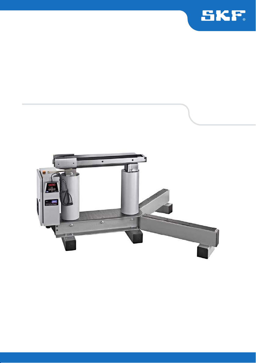
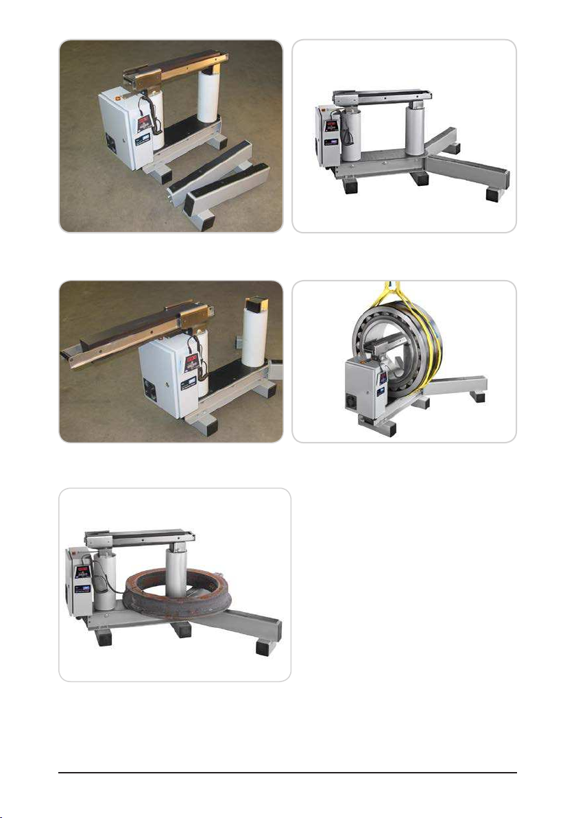
• Versatile heater design: two bearing/workpiece heating positions
TIH L heaters are designed for applications where the bearing is to be heated
vertically to be mounted on an horizontal shaft and applications where the bearing
or workpiece is to be heated horizontally to be mounted on a vertical shaft. See the
illustrations at the beginning of this manual.
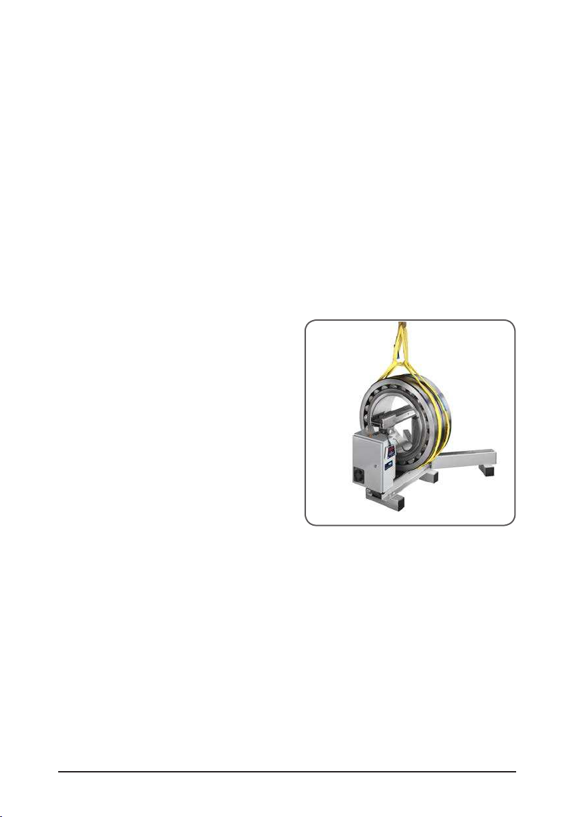
The workpiece can therefore be located either over the (sliding) yoke or over the
outermost inductive coil. Bearing should preferably be heated over the (sliding) yoke
while heavy workpiece can be heated over the inductive coil (see chapter 5.8).
• Remote control panel
To improve the ease of use and to help reduce the risk of contact with the hot
bearing during operation, the TIH L heater is supplied with a remote control panel
which can be detached from the heater.
• Sliding yoke
To facilitate the handling of the yoke while placing the bearing around it or around
the induction coil, the TIH L is fitted with a sliding arrangement for the yoke. See the
illustrations at the beginning of this manual.
• Bearing supports
To support large workpiece when positioned horizontally around the induction
coil, the TIH L induction heater is provided with two bearing supports. See the
illustrations at the beginning of this manual.
2. Description
The operation of the heater is controlled by the internal electronics in either of two
modes. The operator can either select the desired temperature of the bearing in TEMP
MODE or set the length of time that the bearing will be heated in TIME MODE. The power
level can be adjusted to 100% or 50% for slower heating of sensitive workpieces (for
example, bearings with C1 or C2 clearance).
2.1 Components
The TIH L induction heater contains a U-shaped iron core with two induction coils
surrounding the respectively vertical supports. Bearing supports are delivered to be
mounted on the heater. A detachable remote control panel is included. The remote control
electronics and the internal electronics, control the operation of the heater. A sliding yoke
allows the workpiece to be placed onto the heater. A temperature probe is included with
the heater. Heat-resistant gloves are also included.
English

8 SKF TIH L
2.2 Technical data
Designations type
TIH L 3 3 / LV
TIH L 3 3 / MV
TIH L 4 4 / LV
TIH L 4 4 / MV
TIH L 7 7 / LV
TIH L 7 7 / MV
Operating area Voltage
Width
(dm)
Height
(dm)
LV: 200-240V (Low Voltage)
MV: 400-460V (Medium Voltage)
Tecnhnical data
Voltage (±10%) MV: 400-460V / 50-60Hz
LV: 200-240V/50-60Hz
Recommended line
protection
TIH L33/MV: 32 A and TIH L33/LV: 63 A
50 A fuse rating for TIH L44 and TIH L77 MV execution
100 A fuse rating for TIH L44 and TIH L77 LV execution
Power consumption
(maximum)
TIH L33: MV & LV: 15 kVA
TIH L44 & TIH L77: MV: 20,0-23,0 kVA, LV: 20,0-24,0kVA
Temperature control 0-250 °C (32-482 °F); in steps of 1°
Probe type thermocouple, K type
Probe maximum
temperature
250 °C (482 °F)
Time mode 0-99,9 minutes; in steps of 0,1 minute
100-120 minutes; in steps of 1 minute
Power range 100% - 50%
Demagnetisation automatic; residual magnetism <2A/cm
Overall dimensions
with bearing supports
(w ™ d ™ h)
TIH L 33:
Exc. legs 400 ™ 743 ™ 550 mm (15.75 ™ 29.25 ™ 21.65 in.)
Inc. legs 795 ™ 1 123 ™ 550 mm (31.3 ™ 44.21 ™ 21.65 in.)
TIH L 44:
Exc. legs 1 200 ™ 600 ™ 850 mm (47.3 ™ 23.6 ™ 33.5 in.)
Inc. legs 1 550 ™ 1 330 ™ 850 mm (61 ™ 52.4 ™ 33.5 in.)
TIH L 77:
Exc. legs 1 320 ™ 600 ™ 1 150 mm (52 ™ 23.6 ™ 45.3 in.)
Inc. legs 1 850 ™ 1 330 ™ 1 150 mm (72.8 ™ 52.4 ™ 45.3 in.)

9SKF TIH L
Area between
supports
(width ™ height)
TIH L 33: 300 ™ 320 mm (11.8 ™ 12.6 in.)
TIH L 44: 425 ™ 492 mm (16.7 ™ 19.4 in.)
TIH L 77: 725 ™ 792 mm (28.5 ™ 31.2 in.)
Coils diameter TIH L 33: 150 mm (5.9 in.)
for minimum workpiece bore diameter of 160 mm (6.3 in.)
TIH L 44 & TIH L77: 175 mm (6.9 in.)
for minimum workpiece bore diameter of 185 mm (7.3 in.)
Weight with bearing
supports
TIH L 33: 140 kg (309 lb)
TIH L 44: 324 kg (714 lb)
TIH L 77: 415 kg (914 lb)
Workpiece maximum
weight
Bearing TIH L 33: 700 kg (1 543 lb)
Bearing TIH L 44 & TIH L77: 1 200 kg (2 600 lb)
Solid component: consult SKF
Maximum heating
temperature
approx. 250 °C (482 °F)
Depending on bearing or workpiece weight.
For higher temperatures, please contact SKF.
Standard yoke
cross section
TIH L 33: 80 ™ 80 mm (3.15 ™ 3.15 in.)
for minimum bearing bore diameter of 115 mm (4.5 in.)
TIH L 44 & TIH L77: 100 ™ 100 mm (3.9 ™ 3.9 in.)
for minimum bearing bore diameter of 150 mm (5.9 in.)
3. Installation of mains plug
A qualified electrician must install a suitable mains plug. The correct supply voltage is
shown in the designations in section 2.2.
The wires should be connected as follows:
TIH Lxx/MV, TIH Lxx/LV with 200V-3 phases, and all other three phases supply
execution.
Colour of TIH Lxx/MV wire Mains supply terminal
yellow / green ground
blue phase 1
brown phase 2
Connect the TIH L to only two of the three phases.
TIH Lxx/LV with single phase supply.
Colour of TIH Lxx/LV Mains supply terminal
yellow / green ground
blue neutral
brown phase
English

10 SKF TIH L
4. Preparation for use
• Place the TIH L in the horizontal position on a stable surface.
• Assemble the bearing support with the supplied bolts.
• Connect the mains plug to a suitable mains supply.
• Plug the remote control into the connector on the heater electrical cabinet.
• Slide the sliding yoke in open position. See the illustrations at the beginning of
this manual.
• For workpieces heated over the sliding yoke, follow these steps:
- Lift the workpiece over the heater operating area using appropriate lifting
equipment.
- Slide the yoke through the workpiece bore diameter.
- Close the sliding yoke so that it completely covers the top of both vertical supports
• For workpieces heated around the induction coil, follow these steps:
- Place the workpiece over the induction coil using appropriate lifting equipment.
- For best performance, adjust the position of the workpiece so that the induction
coil is in the centre.
- Close the sliding yoke so that it completely covers the top of both vertical supports.
• If you will use TEMP MODE, plug the temperature probe into its socket on the heater
electrical cabinet. Place the magnetic end of the probe on the inner ring of the
bearing or on the innermost surface of the workpiece.
• Switch on the TIH L with the main switch of the heater electrical cabinet
• Observe the self-test of the remote control display and signal tone.

11SKF TIH L
5. Operation
5.1 Function of displays
• The remote control display shows the selected time
or temperature for heating.
• The power LED’s show the selected power setting. STARTSTOP50%100%POWERTIH RCDisplay Indication
t time in minutes
°C temperature in degrees Celsius
°F temperature in degrees Fahrenheit
5.2 Function of buttons
Button Function
POWER Press to adjust the power. The selected power is indicated with
an LED
MODE Press to switch between TIME MODE and TEMP MODE
UP (+) Press to increase the value shown on the remote control display
DOWN (-) Press to decrease the value shown on the remote control display
START / STOP Press to start or stop the heater. The LED on the START / STOP
button is lit when the heater is heating and flashes during
temperature measurement
5.3 TEMP MODE
• If the remote control display shows ‘t’, press MODE to select TEMP MODE. The remote
control display shows °C or °F in TEMP MODE.
• The selected temperature is shown on the remote control display. The default
temperature for bearings is 110 °C (230 °F). If a different temperature is desired, press
UP or DOWN to adjust the temperature in steps of 1°.
• It may be desirable to heat bearings to temperatures above 110 °C (230 °F) for
increased mounting time. Consult the SKF bearing specifications to determine the
maximum permitted temperature. Always ensure the bearing does not lock due to an
excessive expansion of the inner ring compared to outer ring. See section 5.8.
• If needed, press POWER to select the power level. Use the guidelines in section 5.8 to
determine the correct power setting.
• Make sure the temperature probe is mounted on the bearing inner ring.
• Press START / STOP to start the heater. The remote control display shows the
current temperature of the workpiece. The flashing warning light indicates an ongoing
induction heating process.
English

12 SKF TIH L
• During heating the selected temperature can be displayed for 1 second by pressing MODE.
• When the selected temperature has been reached, the heater demagnetises the
workpiece, switches off, and generates an acoustic signal for 10 seconds or until
START / STOP is pressed.
• Press START / STOP to cancel the acoustic signal and stop the heater.
• Remove the workpiece with proper handling equipment.
• If the workpiece remains on the heater, the heater will start again when the
temperature of the workpiece drops 10 °C (18 °F). Press START / STOP to stop the
heater and demagnetise the workpiece.
• The TIH L is now ready to heat another workpiece with the same settings.
5.4 TIME MODE
• If the remote control display shows °C or °F, press MODE to select TIME MODE. The
remote control display shows ‘t’ in TIME MODE.
• Press UP or DOWN to adjust the time in steps of 0,1 minute (up to 99,9 minutes) and
1 minute (100 - 120 minutes).
• Press POWER to select the power level. Use the guidelines in section 5.8 to determine
the correct power setting.
• Press START / STOP to start the heater. The remote control display shows the time
that remains. The flashing warning light indicates an ongoing induction heating
process.
• During heating, the temperature measured by the probe can be displayed for a couple
of seconds by pressing MODE.
• When the time has elapsed, the heater demagnetises the workpiece, switches off, and
generates an acoustic signal for 10 seconds.
• Press START / STOP to cancel the acoustic signal and stop the heater.
• Remove the workpiece with proper handling equipment.
• The TIH L is now ready to heat another workpiece with the same settings.
5.5 Temperature measurement
When the heater is not operating, the temperature of the workpiece can be measured by
pressing MODE and START / STOP at the same time. The LED on the
START / STOP button flashes during temperature measurement. Press START / STOP to
cancel temperature measurement.
5.6 Change of temperature unit
Press MODE and UP at the same time to switch between °C and °F.
The temperature unit setting remains the same even after disconnection from mains
power.

13SKF TIH L
5.7 Demagnetisation
The workpiece is automatically demagnetised when heating is complete. Demagnetisation
will not occur if the power is interrupted or the main switch is switched off. To use the
TIH L for demagnetisation only, select TIME MODE and set the time to 0,1 minute
(6 seconds).
5.8 Power level selection
When heating bearings with an induction heater, most of the heat will be generated in the
inner bearing race. The heat will then be transferred through the bearing. It is therefore
important that bearings with reduced internal clearance are heated slowly. Slow heating
ensures that the bearing expands more evenly, thereby preventing damage to the bearing.
The shape, weight, size, and internal clearances all affect the amount of time required to
heat a bearing. The large variety of bearing types precludes the possibility of providing a
specific power level setting for each type. Instead, the following guidelines are provided:
• For sensitive bearings (including bearings with C1 or C2 internal clearance) or bearings
with brass cages, do not exceed 50% power.
• When using accessory smaller yoke, never exceed 50% power.
Bearings should preferably be heated positioned vertically over the sliding yoke. In the
case of horizontal heating please consider the following:
• For SRB or CARB® bearings, special care must be taken when heating in a horizontal
position and subsequent mounting, especially on vertical shafts. The weight of the
rollers will always set themselves in the lowest position possible: they will be in contact
with both raceways, giving a reduction in the internal clearance. For heavy SRB or
CARB® bearings with heavy rollers we strongly recommend the use of roller centering
ring. The roller centering ring keeps the rollers in position in the middle of the
raceways during the heating process and the mounting.
6. Safety features
The TIH L is equipped with the following safety features:
• Automatic overheating protection.
• Automatic current control.
• Over-current circuit breaker.
• In the TEMP MODE the heater will switch off if the temperature probe does not register
a temperature increase of 1 °C (1.8 °F) every 1 minute (1.00 minute). To increase the
interval to 2 minutes (2.00 minute). press MODE and DOWN at the same time.
• Flashing warning light indicates ongoing heating process.
English

14 SKF TIH L
7. Troubleshooting
Display Fault Action
E03E Overheated coil
Wait until the induction coil cools. Switch
the heater OFF and then back ON
E05E Temperature increase of less
than 1 °C (1.8 °F) every 1
minute (or every 2 minutes)
Check the temperature probe
connection. If the connection is OK,
select the 2 minutes interval as
described in section 6 or operate the
heater in TIME MODE
E06E Temperature probe not
connected (or defective) or
excessive temperature drop
Check the temperature probe
E10E Electronics communication
problem
Switch the heater OFF and then back
ON. If problem remains return the TIH
to SKF for repair
E11E Electronics communication
problem
Switch the heater OFF and then back
ON. If problem remains return the TIH
to SKF for repair
E12E Electronics communication
problem
Switch the heater OFF and then back
ON. If problem remains return the TIH
to SKF for repair

15SKF TIH L
8. Spare parts
Designation Description
TIH L33-PMV Power print 400-460V, 50-60 Hz
TIH L33-PLV Power print 200-240V, 50-60 Hz
TIH L33-Y12 Yoke 80 ™ 80 mm (3.15 ™ 3.15 in.) cross section,
complete with sliding rails for TIH L33 heater type
TIH L33-Y8 Yoke 55 ™ 55 mm (2.17 ™ 2.17 in.) cross section
TIH L33-Y6 Yoke 40 ™ 40 mm (1.57 ™ 1.57 in.) cross section
TIH RC3 Remote control for TIH L33 type
TIH L-PMV Power print 400-460V, 50-60 Hz
TIH L-PLV Power print 200-240V, 50-60 Hz
TIH L44-Y15 Yoke 100 ™ 100 mm (3.9 ™ 3.9 in.) cross section,
complete with sliding rails for TIH L44 heater type
TIH L44-Y10 Yoke 70 ™ 70 mm (2.7 ™ 2.7 in.) cross section,
complete with handles for TIH L44 heater type
TIH L77-Y15 Yoke 100 ™ 100mm (3.9 ™ 3.9 in.) cross section,
complete with sliding rails for TIH L77 heater type
TIH CP Control print
TIH RC2 Remote control for TIH L44 & TIH L77 type
TIH CB50A Circuit breaker 50A for TIH L44/MV and L77/MV
TIH CB100A Circuit breaker 100A for TIH L44/LV and L77/LV
TIH CB32A Circuit breaker 32A for TIH L33/MV
TIH CB63A Circuit breaker 63A for TIH L33/LV
TIH P20 Temperature probe K type incl. cable and plug
English

16 SKF TIH L
Figure 1: TIH L à la livraison
Figure 3: TIH L avec barreau ouvert
Figure 2: L après le montage des supports
de roulement
Figure 4: TIH L avec chauffage de pièce
verticale
Figure 5: TIH L avec chauffage de pièce
horizontale

17SKF TIH L
Français
Déclaration de conformité UE .................................................................................18
Recommandations de sécurité ................................................................................19
1. Introduction ...................................................................................................20
1.1 Utilisation prévue .........................................................................................................20
1.2 Principe de fonctionnement .......................................................................................20
1.3 Caractéristiques distinctives .......................................................................................21
2. Description .....................................................................................................21
2.1 Composants ..................................................................................................................21
2.2 Spécifications techniques ............................................................................................22
3. Installation de la prise secteur ........................................................................23
4. Préparation avant l’utilisation .........................................................................24
5. Fonctionnement .............................................................................................24
5.1 Fonction des écrans ....................................................................................................24
5.2 Fonction des boutons ..................................................................................................25
5.3 TEMP MODE.................................................................................................................25
5.4 TIME MODE ..................................................................................................................26
5.5 Mesure de température ..............................................................................................26
5.6 Modification d’unité de température .........................................................................26
5.7 Démagnétisation ..........................................................................................................26
5.8 Sélection du niveau de puissance. ............................................................................26
6. Dispositifs de sécurité ....................................................................................27
7. Dépannage .....................................................................................................27
8. Pièces de rechange .........................................................................................28
Table des matières
Traduction extraite du mode d’emploi d’origine

18 SKF TIH L
Déclaration de conformité UE
Nous,
SKF Maintenance Products
Kelvinbaan 16
3439 MT Nieuwegein
Pays-Bas
déclarons que le produit suivant:
Le Chauffage Par Induction SKF
TIH L
a été conçu et fabriqué conformément à
la DIRECTIVE EUROPÉENNE RELATIVE AUX BASSES TENSIONS 2014/35/EU
la EMC DIRECTIVE 2014/30/EU, telle qu’elle est décrite dans la norme
harmonisée pour
EN61000-6-4:2007 /A1:2011
EN61000-6-2:2005
EN61000-4-2
EN61000-4-3
EN61000-4-4
EN61000-4-5
EN61000-4-6
EN61000-4-8
EN61000-4-11
A l’exception de l’immunité conformément à la norme EN610006-4-6 dans la
gamme de fréquence allant 17 à 30 MHz.
DIRECTIVE EUROPÉENNE ROHS 2011/65/UE
Nieuwegein, Pays-Bas,
Le 1 mai 2016
Sébastien David
Responsable Développement de Produits et Responsable Qualité
Table of contents
Languages:
Other SKF Heater manuals