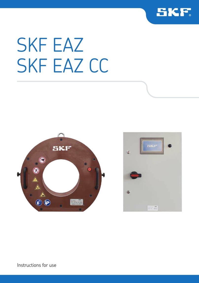
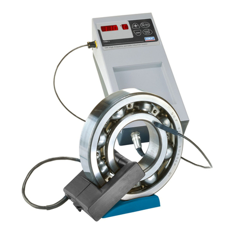
SKF EAZ User manual

Instructions for use
Mode d’emploi
Bedienungsanleitung
Instrucciones de uso
Manuale d’istruzioni
Instruções de uso
使用说明书
Инструкция по эксплуатации
SKF EAZ


English
English 2
Français
Français 14
Deutsch
Deutsch 26
Español
Español 38
Italiano
Italiano 50
Português
Português 62
中文
中文 74
Русский
Русский 86

2SKF EAZ
EC Declaration of conformity ....................................................................................3
Safety recommendations ..........................................................................................4
1. Introduction .....................................................................................................5
1.1 Principle of operation .................................................................................................... 5
2. Technical data ..................................................................................................7
3. Instructions before use .....................................................................................8
4. Operating instructions ......................................................................................9
5. Determination of heating times ......................................................................11
5.1 Determination of heating time for mounting ..........................................................11
5.2 Determination of heating time for dismounting .....................................................11
6. Demagnetisation ............................................................................................12
7. Safety features ..............................................................................................12
8. Maintenance ..................................................................................................13
Table of contents
Original instructions

3
SKF EAZ
English
EC Declaration of conformity
We,
SKF Maintenance Products
Kelvinbaan 16
3439 MT Nieuwegein
The Netherlands
herewith declare that the following product:
Fixed induction heaters
EAZ
has been designed and manufactured in accordance with:
EMC DIRECTIVE 2014/30/EU as outlined in the harmonized norm for
DIN EN 60519-1:2011
DIN EN 60519- 3:2005
DIN EN 60335-1:2012
DIN VDE 298-4
DIN VDE 0848-3-1
DIN EN 61000-6-4
DIN EN 50527- 2-1
VDE 0848-527- 2-1:2012-05
BGV 811
§3 26.BimschV
DIN EN 50413:2009-08
DIN EN ISO 7010
DIN EN 60529
EUROPEAN LOW VOLTAGE DIRECTIVE 2014/35/EU
EUROPEAN ROHS DIRECTIVE 2011/65/EU
Nieuwegein, The Netherlands,
May 2016
Sébastien David
Manager Product Development and Quality

4SKF EAZ
Safety recommendations
• Follow the operating instructions at all times.
• The heater should not be used in areas where there is a risk for explosion.
• Risk of electrical hazard. Only qualified and adequately trained personnel
must be allowed to operate the equipment.
• During the heating process observe a safety distance of 1,5 m (4.9 ft)
with the induction heater.
• Since a magnetic field is generated by the induction heater, people
wearing cardiac pacemakers or having metallic implants must observe
a safety distance of at least 5 metres (16 ft) from the induction heater
during operation. Electronic equipment, such as wristwatches, mobile
phones, may also be affected.
• Use proper handling equipment when lifting heavy workpieces.
Secure the workpiece with appropriate lifting and handling equipment
while heating.
• Never modify the heater.
• Use heat resistant gloves.
• All repair work should be carried out by an SKF repair shop.
• Make sure the supply voltage is correct. Connecting the induction heater
to the wrong voltage supply will void the warranty and probably damage
the heater.
• Always make sure the heater is securely connected to earth.
• Do not expose electronic components to high humidity or water.
• Never introduce body parts into the bore of the heater during operation.
• Do not use the equipment in case of damage or heavy wear is detected
on the heating coil.
• Handle the coil with care to avoid shock loads and jamming during
mounting and dismounting.
• Be aware of pinching risk.
• Cracked rings must not be heated with the electrical induction heater.

5
SKF EAZ
English
1. Introduction
The fixed induction heaters are used for mounting and dismounting of:
• inner rings of cylindrical roller bearings,
• roll groove rings of cold reducing machines and
• roll-body-side labyrinth rings of bearing arrangements.
They are used where large numbers of bearings of the same design are used or where
large bearings with tight fit are frequently mounted and dismounted. They are intended
for one particular bearing and one particular application.
1.1 Principle of operation
The fixed induction heaters consist of a cylindrical
induction coil made of copper wire permanently
mounted in a plastic housing serving as mechanical
extractor. Depending on the size of the heater two
different executions exist as per figure 1 and figure 2.
Fig. 1 Standard execution for rings up
to 380 mm
Fig. 2 Special execution for odd and
large component

6SKF EAZ
The tool is positioned over the ring-shaped part to be heated. The coil is then energised
by the alternating current from the mains supply generating a magnetic field inducing
eddy currents in the ring.
The electrical resistance of the rings will cause it to heat up rapidly which in its turn will
cause the ring to expand. After a pre-determined heating time the ring can be withdrawn.
Fig. 3 The heater is being positioned over the ring
Fig. 4 The heater is positioned over the ring
As magnetic fields with a low frequency penetrate steel to a depth of only a few
millimetres, the roll neck is only heated slightly.

7
SKF EAZ
English
2. Technical data
Product designation :
Recommended
control cabinet
:
Heater dimensions
- Width :
- Housing height :
- Inner diameter :
- Housing width :
- Cable length :
- Weight :
Component dimensions
- Bearing designation or
drawing number :
- Inner diameter (d) :
- Outer diameter (F) :
- Width (B) :
Application
- Drawing number :
- Neck diameter :
- Interference fit :
B
dF

8SKF EAZ
Electrical data
- Mains voltage :
- Mains frequency :
- Current consumption during
mounting :
- Current consumption during
dismounting :
- Insulation resistance :
Heating time
- For mounting :
- For dismounting :
Overheating protection :
3. Instructions before use
A.
Make sure the control panel type SS is
connected to the three-phase mains by an
authorised electrician. Use only SKF control
cabinet to avoid damage in the EAZ induction
heater.
B.
Connect the three-core heater cable (two-
phase + earth) to the connection block inside
the control panel (see enclosed wiring diagram
and parts list). To avoid confusion when
connecting the heater, the cable lugs have
been provided with different bore diameters
which correspond to the studs in the flat
connecting block.
C. The control panel incorporates a timing relay
which is accessible from the outside and
serves for setting the heating time.
D. In order to obtain the full heating capacity
of the coil assure that the cable is connected
without loops.
E. Check for damages before use, specially the
sleeve and power cables. The cables may get
damaged due to the compression or the high
temperatures.
Fig. 5 Connect the control cabinet to
mains supply

9
SKF EAZ
English
F.
Connect the cable for the overheating
protection of the heater to the control
panel.
G. With the door of the control panel
closed, the safety lock can now be
turned to the right with the key and
pushed in.
H. The device is now ready for use but
do not switch on the current until the
heater has been placed over the inner
ring to be withdrawn or mounted.
I. In case the door of the switchboard is
opened, the power supply is cut off by
a safety lock.
J. Let the EAZ acclimate when there is a
temperature change. Use only inside of
buildings.
Fig. 6 Connection diagram of control cabinet
and heater
4. Operating instructions
A. Place the electrical induction heater
over the ring to be withdrawn. The
transportation can be done just by
crane or hoist and with hemp ropes. Do
not use steel ropes.
B. Connect the roll neck to earth.
C. If the abutting parts are provided with
recesses, push the withdrawal bars
towards the inside by loosening the
locking screws and hence positively
engaging the ring. If there are no
recesses behind the ring, slightly
displace the inner ring axially after
the heating process by means of
crowbars until the withdrawing bars
can enter in the gap resulting from
the displacement.
Fig. 7 Do not use steel rope to lift the heater
CIRCUIT BREAKER

10 SKF EAZ
D. After the timing relay is set to the correct heating time, the current may be switched
on. This is done by pushing the handle of the switch upwards.
E. At the end of the pre-determined heating time, the timing relay will automatically
cut off the current. The inner ring can now be withdrawn by evenly pulling the
handles of the induction heater. This must be done as soon as the heater has
switched off so that as little heat as possible will flow from the inner ring into
the roll neck. Be aware of the hot surfaces and use heat protection gloves.
F. Heated rings must immediately after being heated be removed from the induction
heater. By doing this, damage to the bore of the coil is avoided and the induction coil
is protected against heat transmission.
G. If for any reason the circuit is to be interrupted before the pre-determined heating
time is over, press the OFF button of the induction heater or switch off by using the
control cabinet handle.
H. If the ring cannot be withdrawn, for example due to tilting during withdrawal, wait
until ring and roll neck have cooled down before you make another attempt. This
alone will ensure that the temperature difference between neck and ring needed
for dismounting can be obtained. Compressed air may be used to speed up the
cooling process.
I. Electrical induction heaters can also be used for heating the rings during mounting.
For this purpose, place the ring in the bore of the heater and switch on the current.
Here, a shorter heating time as for dismounting is to be set. Please be aware that
the ring will be magnetised after the heating operation.
Please note!
• Cracked rings must not be heated with the electrical induction heater.
• The tool must not be switched on without the steel ring in the bore, as otherwise the
current consumption increases considerably and the coil is heated too rapidly.
• Additional safety is provided by an automatic cutoff interrupting the current as soon
as the temperature of the induction coil exceeds 120 °C. This situation may also
occur after several operations in a row. In this case, it is recommended to cool down
the device with compressed air.
• During dismounting, the roll neck must be connected to earth, for example by means
of a single core cable with magnetic clamp or via the support.

11
SKF EAZ
English
5. Determination of heating times
Prior to any heating operation the correct heating time has to be established. In case this
is not already specified in these instructions please proceed as follows:
5.1 Determination of heating time for mounting
A. Insert the inner ring into the electrical induction heater and switch the heater on at
the switchboard according to chapter 4.
B. Measure the temperature of the ring with a fast responding thermometer such as
the SKF Infrared Thermometer TKTL 30
C. Record the heating time and switch off the heater as soon as the ring has reached a
temperature of 110 °C.
D. Note the heating time together with the technical data in this instruction manual.
E. For all future mounting operations set the time relay on the control panel to the
recorded heating time.
5.2 Determination of heating time for dismounting
A. Push the heater over the ring to be withdrawn and proceed according chapter 4.
B. Set the timing relay at the switchboard at 3 min. and switch on the heater.
C. Measure the temperature at the accessible face of the inner ring, using a fast
responding thermometer.
D. Record the heating time and switch off the unit by pressing the “OFF” button when a
temperature of 120°C has been reached.
E. Dismount the ring and remove it from the heater.
F. Note the heating time together with the technical data in this instruction manual.
G. For all future dismounting operations set the time relay to the recorded heating time.

12 SKF EAZ
6. Demagnetisation
Having been heated with an EAZ heater, the rings are magnetized. In order to prevent
damage during their further use, for example due to steel particles sticking to them, they
must be demagnetised.
For unmounted small-sized rings SKF TIH heater can be used for demagnetisation.
7. Safety features
The heater is equipped with the following safety features:
• Automatic overheating protection.
• Fuses in the control cabinet.
• All metal parts of the heater and the control panel are connected to the earth
conductor of the three-phase mains or are sufficiently insulated.
• Automatic reset in case of extreme conditions such as unstable power supply or
static electricity.

13
SKF EAZ
English
8. Maintenance
To ensure optimum performance and life-time:
• Protect the heater against corrosion, damage and deformation.
• Avoid impacts against the heater.
• Protect the heater from water and very high humidity.
• Always store the heaters during clean and dry conditions.
• For cleaning please use only dry procedures, not water. Switch the heater off
during the process and secure it against accidental switching on.
For the rest the SKF non-adjustable induction heaters type EAZ are considered as
maintenance free.
All repairs should be carried out by an SKF authorised repair facility.
Dispose the heater according to current regulations.

14 SKF EAZ
Déclaration de conformité CE .................................................................................15
Recommandations de sécurité ................................................................................16
1. Introduction ...................................................................................................17
1.1 Principe de fonctionnement .......................................................................................17
2. Spécifications techniques ................................................................................19
3. Instructions avant emploi ...............................................................................20
4. Mode d’emploi ................................................................................................21
5. Détermination des temps de chauffage ...........................................................23
5.1 Détermination du temps de chauffage pour le montage ......................................23
5.2 Détermination du temps de chauffage pour le démontage ..................................23
6. Démagnétisation ............................................................................................24
7. Dispositifs de sécurité ....................................................................................24
8. Maintenance ..................................................................................................25
Table des matières
Traduction extraite du mode d’emploi d’origine

15
SKF EAZ
Français
Déclaration de conformité CE
Nous,
SKF Maintenance Products
Kelvinbaan 16
3439 MT Nieuwegein
Pays-Bas
déclarons que le produit suivant:
Appareils De Chauffage Par
induction À Diamètre Fixe
EAZ
a été conçu et fabriqué conformément à la EMC DIRECTIVE 2014/30/EU,
telle qu’elle est décrite dans la norme harmonisée pour
DIN EN 60519-1:2011
DIN EN 60519- 3:2005
DIN EN 60335-1:2012
DIN VDE 298-4
DIN VDE 0848-3-1
DIN EN 61000-6-4
DIN EN 50527- 2-1
VDE 0848-527- 2-1:2012-05
BGV 811
§3 26.BimschV
DIN EN 50413:2009-08
DIN EN ISO 7010
DIN EN 60529
DIRECTIVE EUROPEENNE SUR LES APPAREILS BASSE TENSION 2014/35/EU
DIRECTIVE EUROPÉENNE ROHS 2011/65/UE
Nieuwegein, Pays-Bas,
Le 1 mai 2016
Sébastien David
Responsable Développement de Produits et Responsable Qualité

16 SKF EAZ
Recommandations de sécurité
• Toujours se conformer aux instructions d’utilisation.
• Ne pas utiliser l’appareil dans des zones où il y a un risque d’explosion.
• Risque d’électrocution. Seul un personnel qualifié et formé à cet effet
devra être autorisé à manipuler l’appareil.
• Pendant le process de chauffage, assurer aux opérateurs une distance
de sécurité d’un mètre par rapport à l’appareil en état de marche.
• Comme l’appareil de chauffage par induction produit un champ
magnétique, les personnes portant un stimulateur cardiaque ou des
implants métalliques, doivent respecter une distance de sécurité
minimale de 5 mètres par rapport à l’appareil de chauffage en
fonctionnement. Des équipements électroniques, comme des téléphones
portables ou des bracelets-montres peuvent être endommagés.
• Utiliser des outils adéquats de manipulation pour lever les pièces
lourdes avec précaution et en toute sécurité.
• Ne jamais modifier l’appareil de chauffage par induction.
• Utilisez toujours les gants résistants à la chaleur.
• Toute réparation doit être effectuée par le Service Après Ventes SKF.
• S’assurer que la tension d’alimentation est correcte. Si le voltage est
erroné, l’appareil sera endommagé et entraînera l’annulation de la
garantie SKF.
• Toujours s’assurer que l’appareil est bien relié à la terre.
• Ne pas exposer l’appareil à un environnement humide ou au contact
direct avec de l’eau.
• Ne jamais introduire une partie du corps dans l’alésage de l’appareil de
chauffage pendant que ce dernier fonctionne.
• Ne pas utiliser l’appareil si vous constatez que la bobine de chauffage est
endommagée ou fortement usée.
• Attention au risque de pincement.
• Manipuler la bobine avec soin pour éviter les chocs et le coincement
pendant le montage et le démontage. Les bagues fissurées ne doivent
pas être chauffées avec l’appareil de chauffage par induction.

17
SKF EAZ
Français
1. Introduction
Les appareils chauffage par induction à diamètre fixe servent au montage et au
démontage de:
• bagues intérieures de roulements à rouleaux cylindriques,
• bagues à rainure de cylindre de machines de formage à froid et
• bagues à labyrinthe à corps de cylindre latéral de paliers.
Ces appareils sont employés là où de grands nombres de roulements de même conception
sont utilisés ou là où de grands roulements à ajustement serré sont fréquemment montés
et démontés. Ces appareils sont destinés à un roulement spécifique et une application
spécifique.
1.1 Principe de fonctionnement
Les appareils de chauffage par induction à diamètre
fixe se composent d’une bobine d’induction cylindrique
constituée de fil de cuivre et montée en permanence
dans un logement plastique servant d’extracteur
mécanique. En fonction de la taille de l’appareil de
chauffage, il existe deux modèles différents ainsi que
le montrent la figure 1 et la figure 2.
Fig. 1 Modèle standard pour bagues
de max. 380 mm
Fig. 2 Mod. spéc. pour compos. de
grandes dim.

18 SKF EAZ
TL’outil est positionné sur la pièce circulaire à chauffer. La bobine est ensuite excitée par
le courant alternatif fourni par l’alimentation secteur pour produire un champ magnétique
induisant des courants de Foucault dans la bague. La résistance électrique des bagues fait
qu’elles chauffent rapidement.
Ce chauffage provoque à son tour une dilatation de la bague. A l’issue d’un temps de
chauffage prédéfini, on peut extraire la bague.
Fig. 3 L’appareil de chauffage par induction est positionné sur la pièce circulaire
Fig. 4 A l’issue d’un cycle de chauffage complet, on peut extraire la bague
Comme les champs magnétiques à basse fréquence pénètrent dans l’acier à une
profondeur de quelques millimètres seulement, la portée de cylindre ne sera chauffée
que légèrement.
Other manuals for EAZ
2
Table of contents
Languages:
Other SKF Heater manuals
Popular Heater manuals by other brands

Dimplex
Dimplex OCR2000 manual

Proton
Proton EX30 Operation manual

HearthRite
HearthRite HB20ML-1 OWNER'S OPERATION AND INSTALLATION MANUAL

STIEBEL ELTRON
STIEBEL ELTRON CK 15 E Operation and installation

Rapid Engineering
Rapid Engineering CGTH-30 Installation & operation manual

VTS Medical Systems
VTS Medical Systems WING W100-200-EC manual