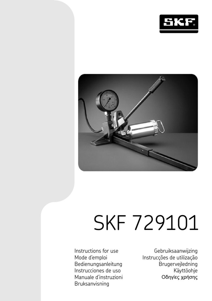
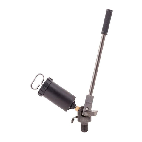
SKF 729101/300MPA User manual

SKF 729101/300MPA
SKF 729101/400MPA
Instructions for use
Bedienungsanleitung | Instrucciones de uso | Mode d’emploi | Manuale d’istruzioni | Instruções de uso
Инструкция по эксплуатации
|
| Ръководство за употреба | Návod k použití | Betjeningsvejledning
Οδηγίες χρήσης | Kasutusjuhend | Käyttöohjeet | Upute za korisnike | Használati útmutató | Naudojimo instrukcija
Lietošanas instrukcija | Gebruiksaanwijzing | Instruksjoner for bruk | Instrukcja obsługi | Instrucţiuni de utilizare
Návod na používanie | Navodila za uporabo | Bruksanvisning | Kullanma talimatları


1
EN English 2
DE Deutsch 13
ES Español 24
FR Français 35
IT Italiano 46
PT Português 57
RU Русский 68
ZH 79
BG ългарски 90
CS Čeština 101
DA Dansk 112
EL Ελληνικά 123
ET Eesti keel 134
FI Suomi 145
HR Hrvatski 156
HU Magyarul 167
LT Lietuviškai 178
LV Latviešu 189
NL Nederlands 200
NO Norsk 211
PL Polski 222
RO Română 233
SK Slovenčina 244
SL Slovenščina 255
SV Svenska 266
TR Türkçe 277

2 EN
Safety precautions .......................................................................................................................... 3
EC Declaration of conformity ........................................................................................................... 3
1. Application................................................................................................................................ 4
2. Description ............................................................................................................................... 5
2.1 General description ......................................................................................................................................5
2.2 Technical data ...............................................................................................................................................6
3. Assembly & operating instructions ............................................................................................ 7
4. Spare parts ............................................................................................................................ 10
5. Recommended mounting and dismounting fluid ...................................................................... 12
Table of contents
Original instructions

3EN
READ THIS FIRST
Safety precautions
Read this instruction for use fully. Follow all safety
precautions to avoid personal injury or property
damage during equipment operation. SKF cannot
be responsible for damage or injury resulting from
unsafe product use, lack of maintenance or incorrect
equipment operation. In case of any uncertainties as
regards the use of the equipment contact SKF.
Failure to comply with the following could cause
equipment damage and personal injury.
• Do ensure that the equipment is only operated
by trained personnel.
• Do wear proper personal protective gear, such
as eye protection and protective gloves, when
operating the equipment.
• Do inspect the equipment and all accessories
carefully before use.
• Do not use damaged components or modify the
equipment.
• Do use clean recommended hydraulic oils
(SKF LHMF 300, LHDF 900 or similar).
• Do not use glycerin or water based fluids as a
pressure medium. Premature equipment wear
or damage can result.
• Do not use the equipment above the stated
maximum working pressure.
• Do not extend the handle in order to reduce
the required force to reach maximum working
pressure. Use hand pressure only.
• Do not apply high pressure oil to the oil inlet
connection.
• Do not use the injector with accessories, which
are rated below the maximum working pressure
of the injector.
• Do not use washers on sealing surfaces.
• Do use a pressure gauge to monitor the oil
outlet pressure.
• Do ensure that all the air has been removed
from the hydraulic system before pressurising
the hydraulic system.
• Do prevent the workpiece (e.g. bearing,
gearwheel or similar item) from being forcibly
ejected upon sudden release of pressure
(e.g. by use of retaining nut).
• Do not handle high pressure pipes when
pressurized. Oil under pressure can penetrate
the skin, causing serious injury or death. If oil is
injected under the skin, seek medical attention
immediately.
• Do not use damaged high pressure pipes.
Avoid sharp bends and kinks when connecting
pipes. Sharp bends and kinks could internally
damage the pipe leading to premature failure.
Applying pressure to a damaged pipe may cause
it to rupture.
• Do not lift the equipment by the pipe or
couplings.
• Do follow local safety regulations.
• Do service the equipment by a qualified
hydraulic technician or SKF Repair Centre.
• Do replace worn or damaged parts with
genuine SKF parts.
EC Declaration of conformity
We, SKF Maintenance Products, Meidoornkade 14,
3992 AE Houten, The Netherlands herewith declare
under our sole responsibility that the products
described in these instructions for use, are in
accordance with the conditions of the following
Directive(s):
MACHINERY DIRECTIVE 2006/42/EC
and are in conformity with the following standards:
EN–ISO 12100, EN–ISO 14121–1, EN–ISO 4413
Houten, The Netherlands, September 2019
Mrs. Andrea Gondová
Manager Quality and Compliance

4EN
1. Application
The SKF oil injection kits 729101/300MPA and
729101/400MPA are used for pressure joints
of all sizes and applications, such as propellers,
rolling bearings, couplings, gears, pulleys, wheels,
flywheels, where the surface pressure is less than
250 N/mm2(350 N/mm2for kit 729101/400MPA).
The adapter block 226402 makes it possible to
connect a high pressure pipe and pressure gauge to
the SKF oil injector 226400 E (226400 E/400).
The design of this adapter block assures a correct
positioning of gauge and injector and offers several
possibilities of working position, such as on the floor,
fixed in a vice or with a G-clamp.

5EN
2. Description
2.1 General description
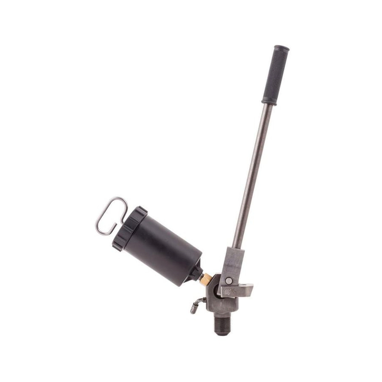
The SKF oil injection kit 729101 consists of the following components:
Description 729101/300MPA 729101/400MPA
Oil injector (D, F, G) 226400 E 226400 E/400
Adapter block, which includes: 226402 226402
– cast iron block (K)
– telescopic steel pipe (H)
– gauge adapter nipple (B)
– gauge nipple O-ring (C)
– filter nipple (90°) (E)
Pressure gauge (A) 1077589 1077589/3
High pressure pipe (L) 227957 A/400MP 227957 A/400MP
Connection nipple 1014357 A –
Connection nipple 1016402 E 1016402 E
Connection nipple 228027 E 228027 E
A
B
C
D
E
F
G
H
K
L
Figure 1

6EN
2.2 Technical data
Injector 226400 E 226400 E/400
Maximum pressure 300 MPa (43 000 psi) 400 MPa (58 000 psi)
Volume per stroke 0,23 cm3(0.014 in3)0,23 cm3(0.014 in3)
Oil reservoir capacity 200 cm3(12.2 in3)200 cm3(12.2 in3)
Weight 2,2 kg (5 lb) 2,2 kg (5 lb)
Adapter block 226402
Maximum pressure 400 MPa (58 000 psi)
Dimensions
– (width) 234 mm (9.2 in)
– (height) 110 mm (4.3 in)
– (length) 570 mm (22 in)
(incl. support)
Weight 2,55 kg (5.6 lb)
Pressure gauge 1077589 1077589/3
Maximum pressure 300 MPa (43 500 psi) 400 MPa (58 000 psi)
Accuracy 1% of full scale 1% of full scale
High pressure pipe 227957 A/400MP 227957 A/400MP
Maximum pressure 400 MPa (58 000 psi) 400 MPa (58 000 psi)
Length 2 m (78 in) 2 m (78 in)
Outer diameter 6 mm (0.24 in) 6 mm (0.24 in)
Connections G 3/4– G 1/4G 3/4– G 1/4
Minimum bending radius 50 mm (2 in) 50 mm (2 in)
Weight 0,5 kg (1.1 lb) 0,5 kg (1.1 lb)
Size and weight 729101/300MPA 729101/400MPA
Carrying Case
dimensions
530 × 110 × 360 mm
(20.9 × 4.3 × 14.2 in)
530 × 110 × 360 mm
(20.9 × 4.3 × 14.2 in)
Total weight
(incl. case)
9,1 kg
(20.1 lb)
9,0 kg
(19.8 lb)

7EN
3. Assembly & operating instructions
If adapter block is to be used on a relatively
flat surface, put the telescopic steel pipe in
corresponding slot of adapter block. Lock it in
position with the quick action lock screw.
The adapter block can also easily be locked on the
top of a working bench by means of a standard
G-clamp. It can also be clamped in a vice.
B
A
C
A. Quick action locking screw
B. Adapter block
C. Telescopic steel pipe
Screw the oil injector on the adapter block until the
thread can be seen in the inside slot.
Screw the rectangular gauge adapter nipple into the
thread of the pressure gauge tightly, so that a good
seal is formed. Make sure the flat surfaces of the
nipple are aligned with the pressure gauge.
The use of a vice, with soft aluminium jaws, can
greatly simplify the mounting of the pressure gauge.
This nipple will remain on the gauge. There is no
need to remove the gauge from the nipple after
using the equipment.
A
A. Gauge adapter nipple

8EN
Push the gauge adapter nipple into the top slot of
the adapter block.
N O T E :
To avoid misalignment the O-ring has to be located
on the flat part of the gauge nipple.
The O-ring has no sealing function, it only helps in
aligning the components.
The following operation should be done carefully.
The illustration shows how the seal will be achieved.
Screw the high pressure pipe nipple into the back
of the adapter block, while gently moving the gauge
adapter nipple in order to secure the correct position
of the high pressure sealing area.
Then screw the oil injector into the block until it is
touching the gauge nipple. Gently loosen and tighten
the pipe and oil injector until the oil injector is in the
correct position, then tighten the high pressure pipe.
Make sure all parts are properly aligned. Failure in
doing so will prevent proper sealing and will cause
leakage. The component design helps achieve an
effective sealing with a moderate tightening torque.
A
CD
E
B
A. Gauge nipple O-ring 226402–2
B. Oil injector 226400 E
C. Gauge adapter nipple 226402–1
D. Adapter block 226402
E. High pressure pipe

9EN
When the oil reservoir (K) is to be charged, the
nozzle is immersed in oil and the piston retracted
by the handle. The oil will then be sucked into the
reservoir.
To allow any air to escape, point the nozzle upwards
and depress the valve ball slightly. Screw the
reservoir onto the injector, the ball is automatically
depressed and the valve opened.
Make a few strokes with the lever to displace any
air trapped in the injector body and then close the
release valve firmly.
If the valve is not tight enough then it can be difficult
to reach the maximum pressure.
N O T E : that the oil reservoir can be refilled
without releasing the pressure from the pump.
Figure 2
The kit is now fully assembled and ready for use.
Ensure that no air is trapped in the system, by
pumping until air-free oil is released from the end
of the high pressure pipe. Thread the swivel nipple,
on the high pressure pipe, in to the application. If
necessary, use any of the connection nipples that
are delivered with the set.
K L
A
D
J
G
H
B
C
E
F

10 EN
4. Spare parts
Designation Description Fig Ref
226400 E
(226400 E/400 )
Oil injector
226400 E–3 Repair kit 2 C + E–J
226400 E–1 Valve screw 2 A, B
226400 E–2 Filter nipple 2 D
920100 B Oil reservoir 2 K
920100 B–1 Oil reservoir O-ring 2 L
226402 Adapter block
226402–1 Gauge nipple 1 B
226402–2 Gauge nipple O-ring 1 C
1077597–1 Filter nipple 90° 1 E
1077589 Pressure gauge (0 – 300 MPa)
1077589/3 Pressure gauge (0 – 400 MPa)
227957 A/400MP High pressure pipe (G 3/4– G 1/4)
1014357 A Connection nipple (G 1/4– G 1/8)
1016402 E Connection nipple (G 1/4– G 1/2)
228027 E Connection nipple (G 1/4– G 3/4)
LHMF 300/5 Mounting fluid (300 mm2/s, 5 litres)
LHDF 900/5 Dismounting fluid (900 mm2/s, 5 litres)
729101–300–CC Toolcase with inlay for 729101/300MPA
TDTC 1/C General toolcase without inlay, size C

11EN
A
B
C
D
E
F
G
H
K
L
Figure 1
K L
A
D
J
G
H
B
C
E
F
Figure 2

12 EN
5. Recommended mounting
and dismounting fluid
SKF mounting fluid
SKF LHMF 300/5 mounting fluid is recommended
when mounting shrink-fitted components with the
SKF oil injection method.
The mounting fluid is recommended for use at a
temperature of 18… 25 °C (64… 77 °F).
The fluid contains anti-corrosive additives.
SKF dismounting fluid
SKF LHDF 900/5 dismounting fluid is recommended
when dismounting shrinkfitted components with the
SKF oil injection method.
The dismounting fluid should be used at a
temperature of 18… 25 °C (64… 77 °F).
The fluid contains anti-corrosive additives.
Due to the high viscosity of the fluid it might be
necessary to operate the pump slowly.
Oil cleanliness requirements
Dirt and metal particles in the oil can cause wear of
the piston mating surfaces, leading to excessive oil
leakage and permanent damage.
The recommended oil cleanliness level should meet
or exceed ISO 4406:1999 20/18/15.
Using fluids, other than oils or SKF mounting and
dismounting fluids, can cause corrosion and/or
damage to the piston mating surfaces.
Do not mix fluids or oils of different brands.
The contents of this publication are the copyright of the
publisher and may not be reproduced (even extracts) unless
prior written permission is granted. Every care has been
taken to ensure the accuracy of the information contained in
this publication but no liability can be accepted for any loss or
damage whether direct, indirect or consequential arising out of
the use of the information contained herein.

13DE
Sicherheitsvorkehrungen............................................................................................................... 14
CE Konformitätserklärung ............................................................................................................. 15
1. Anwendungen......................................................................................................................... 15
2. Beschreibung.......................................................................................................................... 16
2.1 Allgemeine Beschreibung.........................................................................................................................16
2.2 Technische Daten ......................................................................................................................................17
3. Montage- und Bedienungsanleitung........................................................................................ 18
4. Ersatzteile .............................................................................................................................. 21
5. Empfohlene Montage- und Demontageflüssigkeiten................................................................. 23
Inhalt
Übersetzung der Original-Bedienungsanleitungen

14 DE
BITTE ZUERST LESEN
Sicherheitsvorkehrungen
Bedienungsanleitung vollständig lesen.
Sicherheitsvorkehrungen befolgen, um Verletzungen
an Personen oder Sachschäden während des
Betriebs der Ausrüstung zu vermeiden.
SKF haftet nicht für Schäden oder Verletzungen,
die sich aus einem unsachgemäßen Gebrauch des
Produkts, einer mangelhaften Wartung oder einer
fehlerhaften Bedienung der Ausrüstung ergeben.
Falls Fragen zur Handhabung der Ausrüstung offen
sind oder Unsicherheiten bestehen, bitte mit SKF
Kontakt aufnehmen.
Werden die folgenden Anweisungen nicht beachtet,
kann dies zu Schäden an der Ausrüstung sowie zu
Verletzungen von Personen führen.
• Die Ausrüstung darf ausschließlich von
geschultem Personal bedient werden.
• Beim Bedienen der Ausrüstung geeignete
Schutzausrüstung wie beispielsweise
Augenschutz und Schutzhandschuhe tragen.
• Vor Inbetriebnahme sind sämtliche
Ausrüstungs- und Zubehörteile sorgfältig zu
überprüfen.
• Es dürfen keine beschädigten Komponenten
verwendet oder Modifizierungen an der
Ausrüstung vorgenommen werden.
• Von SKF empfohlene, saubere Drucköle
verwenden; z.B. SKF LHMF 300,
SKF LHDF 900 oder ähnlich.
• Keine Flüssigkeiten auf Glyzerin- oder
Wasserbasis als Druckmedium verwenden.
Dies kann zu einem vorzeitigen Verschleiß oder
zu Schäden an der Ausrüstung führen.
• Den angegebenen maximalen Arbeitsdruck des
Geräts nicht überschreiten.
• Auf keinen Fall den Handgriff verlängern,
um den maximalen Arbeitsdruck mit weniger
Kraftaufwand zu erzielen. Der Druck muss
manuell aufgebaut werden.
• Beachten Sie, dass die Drücke an der Ölzufuhr
nicht zu hoch sind.
• Verwenden Sie keine Injektoren plus Zubehör,
die für niedrigere Drücke als den maximalen
Betriebsdruck des Injektors ausgelegt sind.
• Verwenden Sie auf Dichtflächen keine
Dichtscheiben.
• Verwenden Sie zur Überwachung des
Ölablassdrucks ein Manometer.
• Sicherstellen, dass das Hydrauliksystem
vollständig entlüftet wurde, bevor es unter
Druck gesetzt wird.
• Verhindern, dass das Werkstück (z.B. Lager,
Getriebe oder Ähnliches) aufgrund einer
plötzlichen Druckfreisetzung gewaltsam
abgeworfen wird (z.B. durch Benutzen einer
Sicherungsmutter).
• Fassen Sie keine Hochdruckleitungen an, die
unter Druck stehen. Öl kann unter Druck in die
Haut eindringen und zu schweren Verletzungen
oder gar zum Tode führen.
Suchen Sie daher, sollte Öl unter die Haut
gelangen, sofort einen Arzt auf.
• Verwenden Sie keine beschädigten
Hochdruckleitungen. Vermeiden Sie beim
Verbinden der Leitungen scharfe Krümmungen
und Knickstellen. Diese können die Leitung
innen beschädigen und zu frühzeitigen Ausfällen
führen. Druck auf eine beschädigte Leitung
kann zum Bruch führen.
• Heben Sie das Gerät nicht mit Hilfe der Leitung
oder der Verbindungen an.
• Lokale Sicherheitsbestimmungen befolgen.
• Ausrüstung durch einen qualifizierten
Hydrauliktechniker oder das SKF Repair Centre
warten lassen.
• Abgenutzte oder beschädigte Teile durch
Originalteile von SKF ersetzen

15DE
CE Konformitätserklärung
Die SKF Maintenance Products, Meidoornkade 14,
3992 AE Houten, Niederlande erklärt hiermit unter
unserer alleinigen Verantwortung, dass die in dieser
Gebrauchsanweisung beschriebenen Produkte den
folgenden Richtlinien und Normen entsprechen:
MASCHINENRICHTLINIE 2006/42/EC
außerdem stimmen sie mit den folgenden Normen
überein:
EN–ISO 12100, EN–ISO 14121–1, EN–ISO 4413
Houten, in den Niederlanden, September 2019
Mrs. Andrea Gondová
Manager Quality and Compliance
1. Anwendungen
Die Druckölgerätesätze 729101/300MPA
und 729101/400MPA von SKF werden für
Preßverbände in allen Größen und Anwendungen
eingesetzt, zum Beispiel: Propeller, Wälzlager,
Kupplungen, Getriebe, Laufrollen, Räder,
Schwungräder, bei denen der Flächendruck weniger
als 250 N/mm2beträgt (350 N/mm2für Set
729101/400MPA).
Die Gerätesätze können auch zur Montage und
Demontage von SKF Supergrip-Bolzen und
SKF OK-Wellenkupplungen verwendet werden.
Der Pumpenhalter 226402 erlaubt den Anschluß
eines Hochdruckrohres und eines Manometers an
die Pumpe 226400 E (226400 E/400).
Die Gestaltung des Pumpenhalters gewährleistet
eine korrekte Positionierung von Manometer und
Pumpe bei verschiedenen Arbeitsbedingungen,
sei es am Boden oder in einem Schraubstock
eingespannt.

16 DE
2. Beschreibung
2.1 Allgemeine Beschreibung
Der Druckölgerätesatz 729101 von SKF besteht aus folgenden Komponenten:
Beschreibung 729101/300MPA 729101/400MPA
Hochdruckpumpe (D, F, G) 226400 E 226400 E/400
Pumpenhalter bestehend aus: 226402 226402
– Halter (K)
– Teleskopstütze (H)
– Manometeradapter (B)
– Manometernippel O-Ring (C)
– Filternippel (90°) (E)
Manometer (A) 1077589 1077589/3
Hochdruckrohr (L) 227957 A/400MP 227957 A/400MP
Anschlussnippel 1014357 A –
Anschlussnippel 1016402 E 1016402 E
Anschlussnippel 228027 E 228027 E
A
B
C
D
E
F
G
H
K
L
Bild 1.

17DE
2.2 Technische Daten
Hochdruck-Ölpumpe 226400 E 226400 E/400
Maximaler Druck 300 MPa 400 MPa
Hubvolumen 0,23 cm30,23 cm3
Behältervolumen 200 cm3200 cm3
Gewicht 2,2 kg 2,2 kg
Adapterblock 226402
Maximaler Druck 400 MPa
Abmessungen
– (Breite) 234 mm
– (Höhe) 110 mm
– (Länge) 570 mm
(inkl. Teleskopstütze)
Gewicht 2,55 kg
Manometer 1077589 1077589/3
Maximaler Druck 300 MPa 400 MPa
Genauigkeit 1% des Gesamtbereichs 1% des Gesamtbereichs
Hochdruckrohr 227957 A/400MP 227957 A/400MP
Maximaler Druck 400 MPa 400 MPa
Länge 2 m 2 m
Außendurchmesser 6 mm 6 mm
Anschlüsse G 3/4– G 1/4G 3/4– G 1/4
Minimaler Biegeradius 50 mm 50 mm
Gewicht 0,5 kg 0,5 kg
Größe und Gewicht 729101/300MPA 729101/400MPA
Abmessungen Tragekoffer 530 × 110 × 360 mm 530 × 110 × 360 mm
Gesamtgewicht (inkl. Tragekoffer) 9,1 kg 9,0 kg

18 DE
3. Montage- und Bedienungsanleitung
Wenn der Pumpenhalter auf einer flachen Unterlage
benutzt wird (Boden), wird die Teleskopstütze in die
entsprechende Öffnung des Halters gesteckt.
Mit der Schnellspannschraube wird die Stütze im
Halter befestigt.
Der Pumpenhalter kann auch mit einer
Schraubzwinge an der Werkbank oder direkt in
einem Schraubstock befestigt werden.
B
A
C
A. Schnellspannschraube
B. Adapterblock
C. Teleskopstütze
Die Ölpumpe wird in den Pumpenhalter geschraubt,
bis das Gewinde im Einsteckschacht für den
Manometeradapter sichtbar ist.
Der Manometeradapter wird auf das Gewinde des
Manometers geschraubt, bis Dichtheit zwischen den
Anschlussteilen hergestellt ist. (Fest anziehen!)
Das abgeflachte Ende des Adapters sollte parallel
zum Zifferblatt des Manometers stehen.
Die Verwendung eines Schraubstocks mit
weichen Aluminiumbacken kann den Einbau des
Manometers erheblich vereinfachen.
Der Adapter verbleibt anschließend auf dem
Manometer.
Das Manometer muss nach dem Gebrauch nicht
vom Anschlussnippel demontiert werden.
A
A. Manometeradapter
This manual suits for next models
1
Table of contents
Languages:
Other SKF Laboratory Equipment manuals
Popular Laboratory Equipment manuals by other brands

Sartorius
Sartorius Midi Plus quick start guide

Terra Universal
Terra Universal Ductless Exhaust Fume Hood Installation and operating guide

Sigma
Sigma 3-16PK Use and maintenance manual

Solmetex
Solmetex Hg5 Installation and operation manual

Waters
Waters Xevo G2 QTof Operator's, overview and maintenance guide

Reverberi
Reverberi MINI WASH Use and Installation Instructions