SKF 234-13163-9 User manual

Version 04
951-150-032-EN
Service manual
Piston detectors
DE EN FR
Further language versions can be found on the SKF homepage.
Weitere Sprachversionen finden Sie auf der SKF-Homepage.
D‘autres versions linguistiques disponibles sur le site SKF.
DW
O
AD
http://www.skf.com/binary/
EN http://www.skf.com/binary/41-286788/951-150-032-DE.pdf
EN http://www.skf.com/binary/12-286814/951-150-032-EN.pdf
FR http://www.skf.com/binary/43-286786/951-150-032-FR.pdf
ES http://www.skf.com/binary/42-286814/951-150-032-ES.pdf
NL http://www.skf.com/binary/174-286814/951-150-032-NL.pdf
IT http://www.skf.com/binary/44-286814/951-150-032-IT.pdf
ZH http://www.skf.com/binary/20-286814/951-150-032-ZH.pdf
FI http://www.skf.com/binary/154-286814/951-150-032-FI.pdf
EL http://www.skf.com/binary/175-286814/951-150-032-EL.pdf
YES http://www.skf.com/binary/177-286814/951-150-032-JA.pdf
RU http://www.skf.com/binary/39-286814/951-150-032-RU.pdf
PL http://www.skf.com/binary/55-286814/951-150-032-PL.pdf
L+
1
2/4 L-
L+
2/4
1
L-
3
L+
L-
1 (4)
4(1)
with adapters, optionally with cable break protection
Universal Piston Detector
Bipolar Piston Detector
IMPORTANT NOTE!
For use only in combination with SKF lubrication
pumps of series KFAS/KFBS/KFGS in the com-
mercial vehicles and farm machinery.

- 2 -
951-150-032-EN
Version 04
EU Declaration of Conformity in accordance with Directive 2014/30/EU Annex IV
The manufacturer, SKF Lubrication Systems Germany GmbH , Walldorf Plant, Heinrich-Hertz-Str. 2-8, DE - 69190 Walldorf, hereby
declares conformity of the electrical device
Designation: Piston detector
Type: Magnetic sensor M........G
Item number: 234-13163-9 and 234-11454-1
Year of manufacture: See rating plate
with all relevant harmonization legislation of the European Union at the time of placing on the market.
Furthermore, the following Directives and (harmonized) standards were applied in the applicable areas:
2011/65/EU RoHS II
Walldorf, March 31, 2018
Jürgen Kreutzkämper
Manager R&D Germany
SKF Lubrication Business Unit
Stefan Schürmann
Manager R&D Hockenheim/Walldorf
SKF Lubrication Business Unit
Standard Edition
DIN EN 60947-5-1 2007
Correction 2012
DIN EN 50581 2013
EU Declaration of Conformity

- 3 -
951-150-032-EN
Version 04
EN
Masthead
Copyright
© Copyright SKF
All rights reserved.
Warranty
The instructions do not contain any
information on the warranty. This can
be found in our General Terms and
Conditions.
Disclaimer of liability
The manufacturer shall not be held liable for
damage resulting from:
○Improper usage, assembly, operation,
configuration, maintenance, repair, or
accidents
○Improper reaction to malfunctions
○Unauthorized modifications to the
product
○Intentional or gross negligence
○Use of non-original SKF spare parts
The maximum liability for loss or damage
resulting from the use of our products is
limited to the purchase price. Liability for
indirect damage of any kind is excluded.
Masthead
Manufacturer
SKF Lubrication Systems Germany GmbH
Address of manufacturer plants
Headquarters
Walldorf Plant
Heinrich-Hertz-Str. 2-8
69190 Walldorf
Germany
Tel: +49 (0) 6227 33-0
Fax: +49 (0) 6227 33-259
Berlin Plant
Motzener Strasse 35/37
12277 Berlin
Germany
Tel. +49 (0)30 72002-0
Fax +49 (0)30 72002-111
Hockenheim Plant
2. Industriestraße 4
68766 Hockenheim
Germany
Tel. +49 (0)62 05 27-0
Fax +49 (0)62 05 27-101
E-mail: Lubrication-germany@skf.com
www.skf.com/lubrication
This service manual must be en-
closed with the
product documentation
(e.g., feeder documentation).

- 4 -
951-150-032-EN
Version 04
EN Table of contents
Explanation of symbols and signs
General warning Symbol Meaning
Wear personal protective gear
(face mask) Chronological instructions
Wear personal protective gear
(gloves) Bullet list items
Wear personal protective gear
(protective clothing)
Indicates the requirements that must be
met for the actions described
in the following
Pressure injection General notes
Hot surfaces
Warning level Consequence Probability
DANGER Death, serious
injury Immediate
WARNING Serious injury Possible
CAUTION Minor
injury Possible
NOTE Property damage Possible
Table of contents
EU Declaration of Conformity 2
Masthead 3
Explanation of symbols and signs 4
1. Safety instructions 5
2. Scope of delivery/storage 5
2.1 Storage 5
3. Overview, functional description 6
3.1 Progressive feeder overview with universal
piston detector 234-13163-9 or
bipolar piston detector 234-11454-1 6
3.2 Design 7
3.2.1 Function 7
3.3 Application in commercial vehicles or
farm machinery in combination with a
KFAS/KFBS or KFGS pump 8
3.4 Information on feeder series
VP; VPB; VPK; PSG1; PSG2; PSG3 8
4. Technical data 9
4.1 General technical data 9
5. Assembly 11
5.2 Assembly of the new piston detector 12
5.1 Disassembly of the old piston detector 12
5.3 Conducting initial functional test 13
6. Malfunctions, causes, and remedies 14
7. Spare parts 15

1
2
- 5 -
951-150-032-EN
Version 04
EN
1st Safety instructions /2. Delivery and storage
1. Safety instructions
To convert the piston detector, consult the
documentation for the feeder
(lifecycle manual, assembly instructions) in
which the old piston detector is used. The
safety instructions in that documentation
must be observed in full.
Further:
○The operator must ensure that these
conversion instructions and the cor-
responding feeder documentation have
been read by the person who converts
the piston detector or supervises or in-
structs said person.
○Before removing the defective piston de-
tector, depressurize the affected feeder.
○The operator must also ensure that the
staff fully understands the content of the
instructions.
2. Scope of delivery/storage
The conversion kit for the piston detectors
includes a feeder-specific adapter.
The piston detectors may be used only with
this adapter.
A stopper and a cable adapter are also en-
closed for the feeder version.
The scope of delivery also includes these
conversion instructions.
2.1 Storage
Storage conditions- See feeder documenta-
tion and:
○Store in the original product packaging.
○Store protected from nearby sources of
heat or cold.
○The permissible storage temperature
range corresponds to the operating tem-
perature range (see “Technical data”).
○Putting the products into operation or
operating them without having read the
instructions is prohibited.

- 6 -
951-150-032-EN
Version 04
EN 3. Overview, functional description
3.1 Progressive feeder overview with universal piston detector 234-13163-9 or bipolar piston detector 234-11454-1
Mounting dimensions, universal and bipolar piston detectors, Fig. 1
VPBM VPK VP SSV
PSG1 PSG2 PSG3 SSVD
SW 12
44-0159-2507
SW 12
44-0159-2508
SW 24
44-0159-2510
SW 17
44-0159-2509
SW 17
44-0159-2509
SW 12
44-0159-2508
SW 13
419-74031-1
SW 13
419-74031-1
53,6 (53,3)
53,5 (53,5)
53,5 (53,5)
53,8 (53,5)
53,8 (53,5)
40 (39,5)
54,3 (54) 54,3 (54)
(....) = mounting dimension of previous piston detector
3. Overview, functional description

3
- 7 -
951-150-032-EN
Version 04
EN
3. Overview, functional description
3.2 Design
The universal piston detector
234-13163-9 and the bipolar piston detec-
tor 234-11454-1 are position sensors that,
together with the respective pressure-re-
sistant adapter, are screwed into the feeder.
Through the closed adapter, the sensors
detect the feeder piston without coming into
direct contact with it.
Hydraulic pressure spikes therefore do not
act directly on the front sensor surface the
piston detectors.
There are different adapters depending on
the feeder series. These differ in terms of
thread size and clearance. They are specifi-
cally tailored to the respective feeder type
and piston type.
The piston detectors automatically detect
the clearance between the feeder piston and
the piston sensor following several feeder
strokes and adjust themselves automatically.
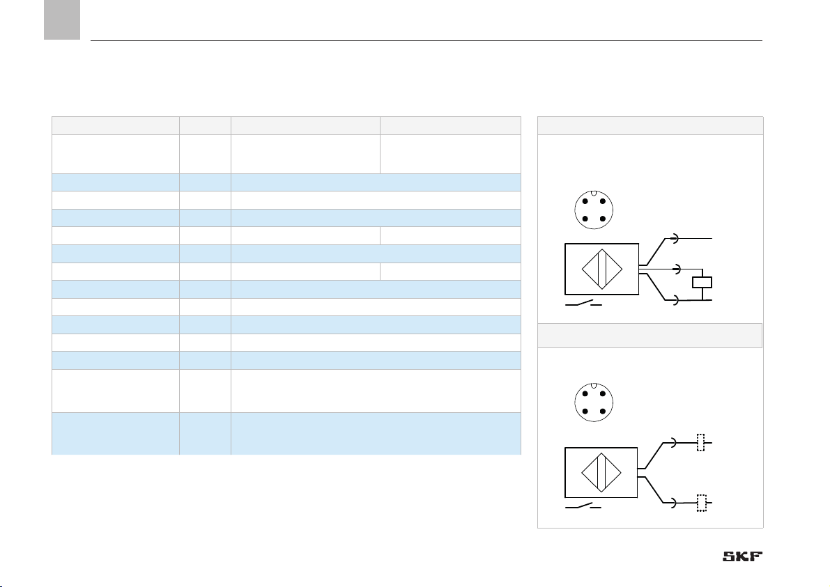
The universal piston detector automatically
detects the customer’s plug/cable assign-
ment, 2-wire design or 3-wire design (with
cable break protection).
The universal piston detector is not suitable
for usage in vehicles with KFGS or KFGL
lubrication pump due to an undefined pin
assignment. The bipolar piston detector is to
be used in this case.
The bipolar piston detector is available only
in a 2-wire design. The signal voltage can be
applied to either pin 1 or pin 4.
3.2.1 Function
When the piston detector is actuated (piston
stroke), a yellow LED lights up and indicates
correct functioning of the piston detector.
If a piston detector with adapter is already
installed, the piston detector can be replaced
subsequently during operation. The adapter
must not be removed while removing the
existing piston detector!
Problems cannot occur in the stopper pres-
sure range of the sensor surface/feeder.
The piston detectors are available with a
corresponding adapter and cable harness
(cable harness only on feeder series SSV/
SSV D) as a replacement for all previous de-
tectors of feeder series PSG1, PSG2, PSG3,
VP, VPK, VPB, SSV, and SSV D.

- 8 -
951-150-032-EN
Version 04
EN 3. Overview, functional description
3.3 Application in commercial vehicles or
farm machinery in combination with
a KFAS/KFBS or KFGL pump
Bipolar piston detector 234-11454-1
is a replacement for the following piston
detectors.
Bipolar
piston detector
Replaces previous
piston detectors
234-11454-1 177-300-091
177-300-092
177-300-096
If a universal piston detector has been or-
dered accidentally instead of a bipolar piston
detector, inspect it for correct connection
before installing it in the feeder. This is done
by connecting the electrical plug connection
(plug M12x1). Then switch on the KFG pump
and hold a metallic object in front of the
face of the piston detector. If the yellow LED
If the piston detector is mounted (in
contrast with its previous mounting
position) on the opposite side of the
feeder, the feeder piston must also
be rotated.
See the respective feeder docu-
mentation for a description of
conversion.
lights up (actuation of the piston detector),
the connection was established correctly. If
this is not the case, switch the pin assign-
ment in pin 4 (+) and pin 1 (-) in the power
lead.
3.4 Information on feeder series
VP; VPB; VPK; PSG1; PSG2; PSG3
A detailed terminal diagram for con-
necting the bipolar piston detector
to a KFAS, KFBS or KFGS pump is
available at the links on page 1 in the
respective national languages (at-
tachment to the PDF).
2
3
4
5
7
6
1
BN
KFGS...
F
2 3 4 5 6 7
X1
RD-BK
BU
PK
VT-GN
DK SL2
2,4 W
SL1
2,4 W
YE
BK
PS
+
31 15
3
2
4
1
1
2
3
max
L+
L-
1 (4)
4 (1)
6
5
BN
KFAS
KFBS
KFGS
L+
1
2/4 L-
o o s
So
F
u
s o
s o
o
1 31 Brown
2 15 Red/Black
3 DK Blue
4 SL2 Pink
5 ZDS(+) Yellow
6 ZDS Black
7 SL1 Purple/Green
C
So
F
u
s o
s oo
1 (+) BN Brown
2 WH White
3 BL Blue
4 BK Black
Bipolar piston detector
PN: 234-11454-1
Universal piston detector
PN: 234-13163-9
C
a
e
or: 997-000-650
Pump cable harness, pin 5 (+), wire color yellow =>>
=>>piston detector cable harness, pin 1, wire color
brown
Pump cable harness, pin 6, wire color black=>>
=>> piston detector cable harness, pin 4, wirecolor black
! "u# $%&'t %() y*t+ , *-+ $, ') y- ,#.
Walldorf Plant
Heinrich-Hertz-Str. 2-8
DE - 69190 Walldorf
Tel.: +49 (0) 6227 33-0
Fax: +49 (0) 6227 33-259
E-mail: [email protected]
www.skf.com/lubrication
9/0 0/1 1 2/ 34 5 10
!6 7!8 7!
GS
v
+
:%& ;
+;
u# $ %& 't % ()
cut
C
a
e <
T
=>?@BCl E@CG> C? mH> IJ IK=? ?H B@KH>@ BG L@ KM N@ IKHB E=K=OKH > mH > N P?N I
H m I= >@= I QRT UVQ RXUVQ R
G
U L@ KM OH BK >Hl PB@K YZ [\]

EN
4. Technical data
4
- 9 -
951-150-032-EN
Version 04
4. Technical data
4.1 General technical data
General data Designation Dimension drawing
Field of application Lubricant feeders
Ambient temperature [°C] -40 ....+85
Principle of operation Piston detector/position sensor
Material Housing: Stainless steel; plug: PEI
Mounting type Mountable flush in associated adapter
Tightening torque [Nm] 7 ±0.5
Circuit state display LED Yellow/lights up on damping
Electrical connection M12x1 plug-in connection, gold-plated contact
Sensing range Universal piston detector
Sensing distance [mm] 2.6 condition on delivery
Effective sensing distance (Sr) [mm] 2.6 ±10%
Sensing distance after 3x
0....4.2 mm strokes [mm] 3.3 ±20%, tracked
Hysteresis [% of Sr] ≤ 20 / ≤ 25, tracked
Accuracy/deviations
Switching point [% of Sr] ±10%
Reproducibility [% of Sr] ±10%
Permiss. operating pressure
with associated adapter [bar]
Identical to permiss. operating pressure of the
feeder in which the sensor with adapter is installed
(see feeder documentation)
8,5
15
M10x0,8
52
SW10
M12x1
8
8,7
3
LED
L+
1
2/4 L-
4
1
3
2
Connector pin assignment without cable
break protection 2-wire DC PNP/NPN

EN 4. Technical data
- 10 -
951-150-032-EN
Version 04
Electrical data Universal Piston Detector Bipolar Piston Detector Universal piston detector
Design 3-wire DC PNP
2-wire DC PNP/NPN 2-wire DC PNP/NPN
Operating voltage [V] 10-36 DC, supply class 2 per cULus
Power consumption [mA] < 5
Safety class III
Polarity reversal protection Yes Reverse polarity
Output function NO-contact
Voltage drop [V] 3.5 4.5
Minimum load current [mA] 5
Residual current [mA] < 0.8
Current-carrying capacity [mA] 100
Short-circuit-proof Yes
Overload-proof Yes
Switching frequency [Hz] 10, with damping surface Ø 4mm to 7 Hz
Protection class [IP] IP65 / IP68 / IP69K; with cable box screwed
on properly
L+
2/4
1
L-
3
4
1
3
2
Connector pin assignment with cable break
protection 3-wire DC PNP
Bipolar piston detector
L+
L-
1 (4)
4(1)
4
1
3
2

EN
5. Assembly
5
- 11 -
951-150-032-EN
Version 04
Assembly drawing, Fig. 2
5. Assembly
4 3 2 1
4 3 2 1
VPB
VPK
PSG1
VP
PSG2
PSG3
SSV
SSVD
SSV D
5.1 Disassembly of the old piston detector (VPB/VPK/PSG1/VP/PSG2/PSG3/SSV/SSVD)
5.2 Assembly of the new piston detector (VPB/VPK/PSG1/VP/PSG2/PSG3)
5.2 Assembly of the new piston detector (SSV/SSVD)
1
2
2
3
4 4 4
5 6
7
7
88
9
1
6

EN 5. Assembly
- 12 -
951-150-032-EN
Version 04
• Disconnect the electrical connection
cable (2) from the
old/defective piston detector.
• Loosen and unscrew the defective piston
detector (3) from the feeder (4).
Only on feeder versions with sealing ring:
• Remove old sealing ring (5) from the
feeder (4)
(VP; VPB; VPK; PSG1; PSG2; SSV D)
5.2 Assembly of the new piston detector
• Grease the new sealing ring (6) and place
it on the new adapter (7).
• Apply the adapter (7) to the feeder (4)
and tighten with the following torque:
Adapter torques
VP / PSG2 WAF 17 = 20+1Nm
VPK / PSG1 WAF 12 = 15+1Nm
PSG3 WAF 24 = 70±4Nm
SSV / SSVD WAF 14 = 15+1Nm
VPB WAF 12 = 15+1Nm
• Apply new piston detector (8) to the
adapter (7) and tighten gently.
see Figures 1 and 2
• Depressurize the lubrication system and
feeder
• If possible, place a drip pan for the dis-
charging lubricant below the correspond-
ing feeder.
• Place individual parts of the new piston
detector replacement kit (1) on a clean
storage surface.
CAUTION
Pressure hazard
Before beginning conversion work,
depressurize the system in which
the feeder with the piston detector
to be replaced is installed and de-
pressurize the feeder itself.
see Figures 1 and 2
5.1 Disassembly of the old piston detector

EN
5. Assembly
5
- 13 -
951-150-032-EN
Version 04
Avoid uncontrolled tightening of
the piston detector, as this could
cause damage.
Maintain tightening torque of
70.5 Nm.
• Tighten the piston detector (8) with a
torque of 7 0.5 Nm.
• Connect electrical connection cable
(provided by customer) (2) to the piston
detector (8).
In case of different cable connection:
• Remove old connection cable (2).
• In place of the previous connection cable,
connect the supplied adapter cable (9) to
the piston detector (8) and the customer-
provided port
The piston detectors automatically detect
the clearance between the feeder piston and
the piston detector following several feeder
strokes and adjust themselves automatically.
The yellow LED on the piston detector
lights up to indicate an active feeder stroke.
On the subsequent feeder strokes, the signal
from the piston detector must be received by
the customer’s monitoring equipment.
Automatic adjustment is performed after
power is recovered, e.g., after switching the
lubrication system off and then on, and a
functional test is no longer required.
• Attach the adapter cable (9) in a stress-
free position.
• Clean the work area/feeder of lubricant
contamination.
• Remove the drip pan.
See Figure 2
5.3 Conducting initial functional test

EN 6. Malfunctions, causes, and remedies
- 14 -
951-150-032-EN
Version 04
6. Malfunctions, causes, and remedies
Malfunctions table
Malfunction Possible cause Remedy
None
Feeder signal
Socket not connected or connected
incorrectly
Check plug contacts
Install socket correctly
Signal line is broken Check signal line
Piston detected is not installed correctly Check engagement depth of adapter and piston detector, tighten if necessary
Piston detector overtightened Disconnect piston detector, perform functional test, replace piston detector if damaged
Wrong adapter used Use only the adapter appropriate for the respective feeder
Universal piston detector ordered instead
of a bipolar piston detector;
only when connecting to KFG pumps in
vehicle lubrication applications
Swap the pigtails, see Chapter 3.3

EN
7. Spare parts
7
- 15 -
951-150-032-EN
Version 04
7. Spare parts
Spare parts list
Designation Order number Designation Order number Quantity
Universal Piston Detector 234-13163-9 2-wire or 3-wire connection
1x each
Bipolar piston detector 234-11454-1 2-wire connection for vehicle lubrication
VP adapter sleeve 44-0159-2509 VP stopper WVN 501-12x1.5
VPK adapter sleeve 44-0159-2508 VPK stopper WVN 501-10x1.5
VPB adapter sleeve 44-0159-2507 VPB stopper WVN501-10x1
PSG1 adapter sleeve 44-0159-2508 PSG1 stopper 96-9120-0062
PSG2 adapter sleeve 44-0159-2509 PSG2 stopper WVN 532-12x1.5
PSG3 adapter sleeve 44-0159-2510 PSG3 stopper None
SSV / SSVD adapter sleeve 419-74031-1 SSV / SSVD sealing ring 219-13798-3
WARNING!
Adapter sleeves can be changed only on depressurized feeders!

951-150-032-EN
July 2018
Version 04
SKF Lubrication Systems Germany GmbH
Walldorf Plant
Heinrich-Hertz-Str. 2-8
DE - 69190 Walldorf
Tel: +49 (0) 6227 33-0
Fax: +49 (0) 6227 33-259
E-mail: Lubrication-germany@skf.com
www.skf.com/lubrication
Seals
Mechatronics Services
Lubrication
Systems
Bearings
and Bearing
Units
This manual suits for next models
1
Table of contents
Other SKF Security Sensor manuals

SKF
SKF TMSU 1 User manual

SKF
SKF TMEH 1 User manual

SKF
SKF LINCOLN ATEX PSG1 Series User manual

SKF
SKF M Series User manual

SKF
SKF TMEH 1 User manual

SKF
SKF TKSU 10 User manual

SKF
SKF Lincoln 254-15165-9 User manual

SKF
SKF TKED 1 User manual

SKF
SKF LINCOLN Magnetic sensor M G Series User manual

SKF
SKF TKSU 10 User manual
Popular Security Sensor manuals by other brands

ComSonics
ComSonics QAM Sniffer Quick reference guide

jablotron
jablotron JA-151TH manual

Vimar
Vimar By-alarm 01720 quick start guide

Elektrotechnik Schabus
Elektrotechnik Schabus SHT 5001 operating instructions

THORLABS
THORLABS PDB47 C Series Operation manual

GJD
GJD D-TECT R Ricochet GJD830R installation manual