SKF TKBA 10 User manual

Instructions for use
Mode d’emploi
Bedienungsanleitung
Instrucciones de uso
Manuale d’istruzioni
Instruções de uso
使用说明书
Инструкция по эксплуатации
SKF TKBA 10 & 20


English 3
Français 15
Deutsch 27
Español 39
Italiano 51
Português 63
中文 75
Русский 87


3
SKF TKBA 10 & 20
Table of contents
EC Declaration of conformity ................................................................. 4
Safety recommendations ....................................................................... 5
1. Introduction .................................................................................... 6
2. Principle of operation ..................................................................... 7
3. Battery installation ......................................................................... 8
4. Mounting the units ......................................................................... 9
5. Power on ........................................................................................ 9
6. Alignment Condition check ............................................................ 10
7. Correcting misalignment ............................................................... 10
8. Troubleshooting and maintenance ................................................ 13
9. Technical data .............................................................................. 13
Original instructions

4SKF TKBA 10 & 20
EC Declaration of conformity
We,
SKF Maintenance Products
Kelvinbaan 16
3439 MT Nieuwegein
The Netherlands
herewith declare that the following products:
SKF Belt Alignment Tool
TKBA 10 and TKBA 20
has been designed and manufactured in accordance with:
EMC DIRECTIVE 2004/108/EC as outlined in the harmonized norm for
EN 61000-6-2:2005 - Immunity for Industrial Environments,
IEC 61000-4-2:2001, IEC 61000-4-3:2008, IEC 61000-4-8:2001
EN 61000-6-3:2007 - Emission Standard for Residential, Commercial
and light Industrial Environments,
CISPR 16-1-4:2012, CISPR 16-2-3:2010,
CISPR 16-1-1:2010, CISPR 16-1-5:2012
The laser is classified in accordance with the
USA FDA Standard 21 CFR, Ch 1, Part 1040.10 and 1040.11
EUROPEAN ROHS DIRECTIVE 2011/65/EU
Nieuwegein, The Netherlands,
October 2013
Sébastien David
Manager Product Development and Quality

5
SKF TKBA 10 & 20
Safety recommendations
• Always turn off the power of the drive machine before you
start working.
• Always read and follow the operating instructions.
• Never stare directly into the laser beam.
• Never aim the laser beam into another person’s eyes.
• Opening the housing of the laser unit may result in hazardous light
exposure and void the warranty.
• Take care not to pinch your fingers when mounting the units on
the pulley.
• The equipment should not be used in areas where there is a risk
of explosion.
• Never expose the equipment to high humidity or direct contact
with water.
• Have all repair work performed by an SKF repair shop.
WARNING
LASER RADIATION
DO NOT STARE INTO BEAM
CLASS 2 LASER PRODUCT
P
≤
1mW
l
=
635nm
6SKF TKBA 10 & 20
1 . Introduction
Precise alignment of belt driven machinery is essential to reduce both pulley
and belt wear. It can help reduce machinery vibration, which in turn leads to
improved machine performance.
Good pulley alignment can help reduce unscheduled downtime, and can
improve the reliability of your equipment.
The SKF Belt Alignment Tools TKBA 10 and TKBA 20 offer an easy
and accurate method to adjust the machinery so that pulleys are
accurately aligned.

7
SKF TKBA 10 & 20
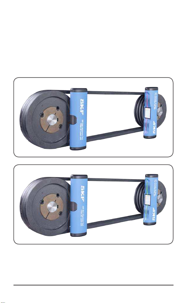
2. Principle of operation
The TKBA 10 and TKBA 20 consist of two units that attach magnetically
to the side of each pulley. The transmitter unit emits a laser line that is
projected onto the reflector unit. The reflector unit has a target area with a
central reference line. The laser line is then reflected to the transmitter unit
for a reading on the second target area, greatly increasing the accuracy.
Depending on the position and orientation of the laser line projected on the
target areas, it is possible to determine the type of misalignment and
how to correct it. Belt alignment is easily performed by adjusting the
moveable machine(s) until the laser lines coincide with the reference lines on
both units.
AB C
Figure 1 Different types of pulley misalignment
AVertical angle misalignment
BParallel misalignment
CHorizontal angle misalignment
8SKF TKBA 10 & 20
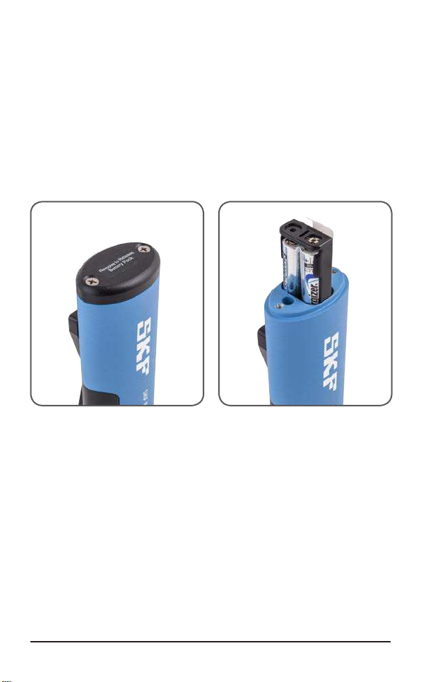
3. Battery installation
The TKBA 10 and 20 are powered with 2 ™ AAA LR03 alkaline batteries.
To insert the new batteries:
• Locate the “Remove to Release battery pack” sticker on the end of the
transmitter unit.
• Remove the two cross-head screws (Fig.2).
• Take out the battery pack holder by pulling on the white strip (Fig.3).
• Carefully insert two new batteries in the holder taking care to observe
polarity. Replace the battery pack holder in the unit and refit the screws.
Figure 2 Battery door Figure 3 Pull on the white strip
Note: Remove the batteries if the transmitter unit is to remain unused for an
extended period.
Other manuals for TKBA 10
1
This manual suits for next models
1
Table of contents
Languages:
Other SKF Tools manuals


SKF
SKF LINCOLN 1154 Instruction Manual

SKF
SKF TKSA 20 User manual

SKF
SKF LINCOLN 1440CLR User manual

SKF
SKF 83753 Instruction Manual

SKF
SKF TMHC 110E User manual

SKF
SKF Lincoln PowerLuber B Series Product manual

SKF
SKF LINCOLN 1134 Product manual

SKF
SKF TMMA 75H User manual

SKF
SKF 729101 User manual

SKF
SKF TKSA 11 User manual


