SKF Lincoln PowerLuber A Series Installation guide

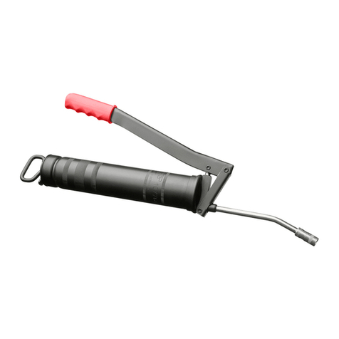
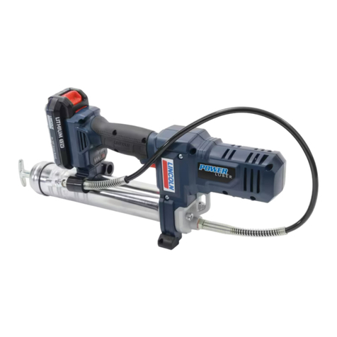
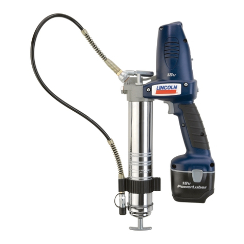
PowerLuber grease gun
Models 1860, 1862, 1864 series “A”
Operation and maintenance
Date of issue October 2016
Form number 404386C
A & A HYDRAULIC
800-992-9898

Contents
Intended use ...................... 2
Safety instruction ................. 3
General power tool safety warnings ... 3
Safety of others ................... 5
Specific Safety .................... 5
Residual risks ..................... 5
Vibration ......................... 6
Maintenance ...................... 6
Protecting the environment ......... 7
Safety instructions for battery
and charger ....................... 7
Electrical safety ................... 9
Tool use and care .................. 10
General Description ................ 11
Inspection ........................ 11
PowerLuber set up ................. 12
Operation ......................... 13
Charger operation ................. 16
Exploded views .................... 18
Service parts list .................. 20
Troubleshooting ................... 22
Warranty ......................... 23
Intended use
The PowerLuber was exclusively designed to
pump and dispense lubricant using 18 V bat-
tery power. Do not exceed the maximum speci-
fication ratings.
2
A & A HYDRAULIC
800-992-9898

Safety instruction
General power tool safety warnings
Save all warnings and instructions for
future reference. The term “power tool” in
the warnings refers to your mains-operated
(corded) power tool or battery-operated (cord-
less) power tool.
1 Work area safety
1.1 Keep work area clean and well lit.
Cluttered or dark areas invite accidents.
1.2 Do not operate power tools in explo-
sive atmospheres, such as in the
presence of flammable liquids, gas-
es or dust. Power tools create sparks
which may ignite the dust or fumes.
1.3 Keep children and bystanders away
while operating a power tool.
Distractions can cause you to lose
control.
2 Electrical safety
2.1 Power tool plugs must match the
outlet. Never modify the plug in any
way. Do not use any adapter plugs
with earthed (grounded) power
tools. Unmodified plugs and matching
outlets will reduce risk of electric shock.
2.2 Avoid body contact with earthed or
grounded surfaces such as pipes,
radiators, ranges and refrigerators.
There is an increased risk of electric
shock if your body is earthed or
grounded.
2.3 Do not expose power tools to rain or
wet conditions. Water entering a pow-
er tool will increase the risk of electric
shock.
2.4
Do not abuse the cord. Never use the
cord for carrying, pulling or unplug-
ging the power tool. Keep cord away
from heat, oil, sharp edges or mov-
ing parts. Damaged or entangled cords
increase the risk of electric shock.
2.5 When operating a power tool out-
doors, use an extension cord suit-
able for outdoor use. Use of a cord
suitable for outdoor use reduces the risk
of electric shock.
2.6 If operating a power tool in a damp
location is unavoidable, use a Resid-
ual Current Device (RCD) protected
supply. Use of an RCD reduces the risk
of electric shock.
3 Personal safety
3.1 Stay alert, watch what you are doing
and use common sense when oper-
ating a power tool. Do not use a
power tool while you are tired or un-
der the influence of drugs, alcohol or
medication. A moment of inattention
while operating power tools may result
in serious personal injury.
3.2 Use personal protective equipment.
Always wear eye protection. Protec-
tive equipment such as dust mask,
non-skid safety shoes, hard hat, or
hearing protection used for appropriate
conditions will reduce personal injuries.
3.3 Prevent unintentional starting. En-
sure the switch is in the off-position
before connecting to power source
and/or battery pack, picking up or
carrying the tool. Carrying power
tools with your finger on the switch or
energising power tools that have the
switch on invites accidents.
3.4 Remove any adjusting key or wrench
before turning the power tool on. A
wrench or a key left attached to a rotat-
ing part of the power tool may result in
personal injury.
3.5 Do not overreach. Keep proper foot-
ing and balance at all times.
This enables better control of the power
tool in unexpected situations.
Read all safety warnings and in-
structions. Failure to follow the
warnings and instructions may
result in electric shock, fire and/
or serious injury.
WARNING
3
A & A HYDRAULIC
800-992-9898

3.6 Dress properly. Do not wear loose
clothing or jewellery. Keep your hair,
clothing and gloves away from mov-
ing parts.Loose clothes, jewellery or
long hair can be caught in moving parts.
3.7 If devices are provided for the con-
nection of dust extraction and col-
lection facilities, ensure these are
connected and properly used.Use of
dust collection can reduce dust-related
hazards.
4 Power tool use and care
4.1 Do not force the power tool.
Use the correct power tool for your
application. The correct power tool will
do the job better and safer at the rate for
which it was designed.
4.2 Do not use the power tool if the
switch does not turn it on and off.
Any power tool that cannot be controlled
with the switch is dangerous and must
be repaired.
4.3 Disconnect the plug from the power
source and/or the battery pack from
the power tool before making any
adjustments, changing accessories,
or storing power tools.
Such preventive safety measures re-
duce the risk of starting the power tool
accidentally.
4.4 Store idle power tools out of the
reach of children and do not allow
persons unfamiliar with the power
tool or these instructions to operate
the power tool. Power tool is danger-
ous in the hands of untrained users.
4.5 Maintain power tools. Check for
misalignment or binding of moving
parts, breakage of parts and any
other condition that may affect the
power tool’s operation. If damaged,
have the power tool repaired before
use. Many accidents are caused by
pooly maintained power tools.
4.6 Keep cutting tools sharp and clean.
Properly maintained cutting tools with
sharp cutting edges are less likely to
bind and are easier to control.
4.7 Use the power tool, accessories and
tool bits etc. in accordance with
these instructions, taking into ac-
count the working conditions and
the work to be performed. Use of the
power tool for operations different from
those intended could result in a hazard-
ous situation.
5 Battery tool use and care
5.1 Recharge only with the battery
charger specified by the manufac-
turer. A charger that is suitable for one
type of battery pack may create a risk of
fire when used with another battery
pack.
5.2 Use power tools only with specific-
ally designated battery packs.
Use of any other battery packs may cre-
ate risk of injury and fire.
5.3 When battery pack is not in use,
keep it away from other metal
objects, like paper clips, coins, keys,
nails, screws or other small metal
objects, that can make a connection
from one terminal to another. Short-
ing the battery terminals together may
cause burns or a fire.
5.4 Under abusive conditions, liquid may
be ejected from the battery; avoid
contact. Liquid ejected from battery
may cause irritation or burns. If
contact accidentally
occurs, flush with water. If liquid
contacts eyes, seek medical help.
Liquid ejected from the battery may
cause irritation or burns.
6 Service
6.1 Have your power tool serviced by a
qualified repair person using only
identical replacement parts. This will
ensure that the safety of the power tool
is maintained.
4
A & A HYDRAULIC
800-992-9898
Safety of others
This appliance is not intended for use by per-
sons (including children) with reduced physical,
sensory or mental capabilities, or lack of expe-
rience and knowledge, unless they have been
given supervision or instruction concerning use
of the appliance by a person responsible for
their safety.
Children should be supervised to ensure that
they do not play with the appliance.
Specific safety
Always wear eye protection. The PowerLuber
can generate up to 7,500 psi (482 bar) at stall.
Use only Lincoln 1218, 1224, 1230 or 1236
outlet whip hoses. Grease injection injuries are
a very serious injury. Hold the hose only in the
area of the spring guard. Avoid accidental
starting. Be sure switch is not depressed when
inserting battery pack. Replace the hose at the
first sign of wear, kink or damage to the outside
jacket. Do not bend the hose so that it becomes
kinked.
Do not overreach. Keep proper footing and
balance at all times. Proper footing and balance
enable better control of the tool in unexpected
situations.
Use safety equipment. Always wear eye
protection.
Dust mask, non-skid safety shoes, hard hat
or hearing protection must be used for appro-
priate conditions.
The gun uses lubricants, that may be flam-
mable and poisonous if ingested. Do not use
gun near open flame or other fire hazards.
Grease is often marketed as high temper-
ature because it must maintain its lubricat-
ing properties in hot areas, but the lubricant
may be flammable if the temperature is too
high. Please read all warnings on lubricants
before using this gun.
Do not use flammable greases with this
grease gun.
Do not use any hose that has not been
approved by Lincoln. Extreme pressure
may cause nozzle extension or whip hose
to burst.
Replace hose at first sign of wear, kinks,
or damage to outside jacket.
Follow whip hose instructions and
warnings. Failure to comply may result in
serious injury or death.
WARNING
Residual risks
Additional residual risks may arise when using
the tool which may not be included in the
enclosed safety warnings. These risks can arise
from misuse, prolonged use etc.
Even with the application of the relevant
safety regulations and the implementation of
safety devices, certain residual risks cannot be
avoided. These include:
• Injuries caused by touching any rotating/
moving parts.
• Injuries caused when changing any parts or
accessories.
• Injuries caused by prolonged use of a tool.
When using any tool for prolonged periods
ensure you take regular breaks.
• Impairment of hearing.
• Health hazards caused by breathing dust de-
veloped when using your tool (example:-
working with wood, especially oak, beech
and MDF.)
Grease gun can develop high pressure up
to 7,500 psi (517 bar). Use safety glasses
and gloves for protection during operation.
Keep hands clear of exposed rubber por-
tion of hose.
Failure to comply may result in serious
injury or death.
DANGER
5
A & A HYDRAULIC
800-992-9898

To reduce risk of injury, user
must read the instruction
manual.
WARNING
Maintenance
The PowerLuber has been designed to
operate over a long period of time with a mini-
mum of maintenance. Continuous satisfactory
operation depends upon proper tool care and
regular cleaning.
Your charger does not require any mainte-
nance apart from regular cleaning.
!Notice
Before performing any maintenance
on tool and/or charger, remove battery
from tool and/or unplug charger.
• Regularly clean ventilation slots in tool
and/or charger using a soft brush or dry
cloth.
• Regularly clean motor housing using a
damp cloth. Do not use any abrasive or
solvent-based cleaner.
Vibration
The declared vibration emission values
stated in the technical data and the declara-
tion of conformity have been measured in
accordance with a standard test method
provided by EN 60745 and may be used
for comparing one tool with another.
The declared vibration emission value may
also be used in a preliminary assessment of
exposure.
When assessing vibration exposure to
determine safety measures required by
2002/44/EC to protect persons regularly
using power tools in employment, an
estimation of vibration exposure should con-
sider, the actual conditions of use and the
way the tool is used, including taking account
of all parts of the operating cycle such as the
times when the tool is switched off and when
it is running idle in addition to the trigger
time.
!Notice
Vibration emission value during ac-
tual use of power tool can differ from de-
clared value depending on ways tool is used.
Vibration level may increase above level
stated.
6
A & A HYDRAULIC
800-992-9898

Safety instructions for
battery and charger
Save these instructions
This manual contains important safety and op-
erating instructions for Lincoln model 1850
battery charger.
Read all instructions
Batteries
• Never attempt to open for any reason.
• Do not expose the battery to water.
• Do not store in locations where the tempera-
ture may exceed 105 °F (40 °C) such as out-
side sheds or metal buildings in the summer.
• Charge only at ambient temperatures
between 50 and 105 °F (10 and 40 °C).
• Charge only using the charger provided with
the tool.
• When disposing of batteries, follow the in-
structions given in the section When dispos-
ing of batteries, follow the instructions given
in the section
“Protecting the environment”, above.
Do not probe with conductive objects.
Do not charge damaged battery.
Replace immediately.
Risk of electric shock 120 V AC present
at charger terminals.
Failure to comply may result in serious
injury or death.
DANGER
Protecting the environment
Separate collection. This product
must not be disposed of with nor-
mal household waste.
Should you find one day that your Lincoln prod-
uct needs replacement, or if it is of no further
use to you, do not dispose of it with household
waste. Make this product available for separate
collection.
Separate collection of used prod-
ucts and packaging allows mate-
rials to be recycled and used
again.
Reuse of recycled materials
helps prevent environmental pol-
lution and reduces demand for
raw materials.
Local regulations may provide for separate col-
lection of electrical products from the house-
hold, at municipal waste sites or by the retailer
when you purchase a new product.
Run battery down completely,
then remove it from tool.
NiCd, NiMH and Li-Ion batter-
ies are recyclable. Take to any au-
thorized repair agent or local
recycling.
7
A & A HYDRAULIC
800-992-9898

Do not expose battery to spark or flame.
Battery liquid may burn.
Do not splash or immerse in water or
other liquids. This may cause premature
cell failure.
Failure to comply may result in serious
injury or death.
DANGER
Never attempt to open battery pack for any
reason. If plastic housing of battery pack
breaks or cracks, return to a service center
for recycling.
Failure to comply may result in serious
injury or death.
DANGER
Do not attempt to charge
damaged batteries.
Do not expose
battery to fire.
Charger
1 Before using this battery charger, read all
instructions and cautionary markings on
battery charger, battery pack, and product
using battery.
2 Do not expose charger to moisture (rain,
snow or frost).
3 Do not abuse cord. Never carry charger by
cord or yank it to disconnect from
receptacle. Pull by plug rather than cord
when disconnecting charger. Replace dam-
aged or worn power cord and strain reliev-
er immediately. Do not attempt to repair
power cord.
4 Make sure cord is located so that it will not
be stepped on, tripped over, or otherwise
subjected to damage or stress.
5 Do not use an extension cord unless
absolutely necessary. Use of improper
extension cord could result in a risk of fire
and electric shock.
6 Do not operate charger if it has received a
sharp blow, been dropped, or otherwise
damaged in any way, take it to a qualified
serviceman.
7 Do not disassemble charger or battery
pack. Take it to a qualified serviceman
when service or repair is required.
Incorrect reassembly may result in risk of
electrical shock or fire.
8 Unplug charger from outlet before
attempting any maintenance or cleaning to
reduce risk of electric shock.
9 Charge the battery pack in a well ventilated
place, do not cover the charger and battery
with a cloth, etc., while charging.
WARNING
Do not charge Lincoln model 1861 battery
packs with any other charger.
To reduce risk of injury, Lincoln model
1850 charger should only be used to
charge Lincoln battery pack model 1861.
Other types of batteries may burst causing
personal injury and damage.
8
A & A HYDRAULIC
800-992-9898

Electrical safety
Your charger is double insu-
lated; therefore no ground wire
is required. Always check that
the mains voltage corresponds
to the voltage on the rating
plate. Never attempt to replace
the charger unit with a regular
mains plug.
!Notice
New batteries are shipped in an
uncharged state and initial charge will re-
quire 12 hours before use.
!Notice
Users in United States:
Applicable fees for collection and recycling
of batteries have been paid to RBRCTM. For
further information, call
1-800-8BATTERY.
10 Do not store the charger or battery packs in
locations (such as a metal tool shed, or a
car in the summer) where the temperature
may reach or exceed 122 °F (50 °C) , which
can lead to deterioration of the battery.
11 Do not charge battery pack when the tem-
perature is below 32 °F (0 °C) or above
104 °F (40 °C). This is very important for
proper operation.
12 Do not incinerate battery pack. Fire may
cause battery pack to explode.
13 Do not short across the terminals of the
battery pack. Extremely high tempera-
tures could cause personal injury or
fire.
14 Charging time will be approximately 1 hour
after the initial charge.
15 When green light comes on indicating
charge is complete, remove battery from
charger. Do not leave battery plugged
into charger for an extended period of
time after charge is complete.
16 Dispose of expended batteries properly.
The Lincoln model 1861 battery pack con-
tains rechargeable, lithium-ion batteries.
These batteries must be recycled or dis-
posed of properly. Drop off expended bat-
tery packs at your local replacement bat-
tery retailer, or your recycling center.
9
A & A HYDRAULIC
800-992-9898

Extreme pressure may cause nozzle
extension or whip hose to burst. Use only
Lincoln approved hoses and follow whip
hose instructions and AVERTISSEMENTs.
Failure to comply may result in serious
injury or death.
AVERTISSEMENT
Tool use and care
Do not continue to hold down trigger if grease
gun is stalled. This could damage the motor or
cause fire.
Disconnect battery pack from tool before
making any adjustments, changing accessories,
or storing the tool. Such preventive safety
measures reduce the risk of starting the tool
accidentally.
Store the tools out of reach of children and
other untrained persons. Tools are dangerous
in the hands of untrained users.
If damaged, have the tool serviced before us-
ing. Many accidents are caused by poorly main-
tained tools.
Use only accessories that are recommended
by Lincoln.
Only accessories that are capable of handling
7,500 psi (517 bar) should be used.
Accessories that may be suitable for one tool
may create a risk of injury when used on
another tool.
Specifications
Basic PowerLuber Model 1860
Operating power 18 V
Maximum operating pressure
Low output 7,500 psi (517 bar)
High output 3,000 psi (206 bar)
Grease reservoir capacity 14.5 oz. (411 g)
Operating temperature range 0 to 122 °F (–18 to +50 °C)
Operating current 4.0 A
Rated current 5.0 A
Lubricant (Grease) Up to NLGI #2
Grease output
Low output 3.5 oz/min. (99 g/min.)
High output 8.9 oz/min. (252 g/min.)
Weight 8.8 lbs. (4,0 kg)
Accessories:
Battery Li-Ion Model 1861
Output 18 V DC
Capacity 3000 mAh
Batter y Charger Model 1850
Input (3.0 A) 12 0 V AC, 50-60 Hz
Outlet Hose Model 1236
Pressure rating 7,50 0 ps i (510 bar)
Lengt h of hose 36 in. (914 mm)
Sound pressure Lp 70.0 dB(A), uncertainty (K) 3 dB(A),
Acoustic power Lw 81 dB(A), uncertainty (K), 3 db(A),
Vibration emission value (ah) 1.1 m/s2, uncertainty (K)
1.5 m/s2.
Note 1: Operating current and grease output data at
1,000 psi (69 bar ).
Note 2: T he de clared vibration tot al value has been meas-
ured in accordance with a standard test method and may
be used for comparing one tool wit h another and the de-
clared vibration total value may also be used in a prelimi-
nary assessment of exposure.
Note 3: The vibration emission during actual use of the
power tool can differ from the declared tot al value depend-
ing on the ways in which the tool is used; and of the need to
identify safety measures to protect the operator that are
based on an estimation of exposure in the actual conditions
of use (taking account of all parts of the operating cycle
such as the times when the tool is switched off and when it
is running idle in addi tion to the trigger time).
PowerLuber models and components
Sales model Battery Charger Case
1860 1861 NA NA
1862 1861 1850 286358
1864 1861 1850 286358
10
A & A HYDRAULIC
800-992-9898

General description
The Lincoln PowerLuber is a battery operated
grease gun developed for manual lubrication of
grease points.
The PowerLuber is driven by a small, low
voltage electric motor connected to a three-
stage planetary gear transmission. The rotary
motion of the motor is converted into a recipro-
cating motion of the plunger using a yoke
mechanism. The PowerLuber is a positive dis-
placement single acting pump.
Thermal protector
The thermal protector acts as a safeguard,
stopping the motor if gun is run continuously at
maximum pressure.
Fig. 1
2
16
7
8
1
17
5
Inspection
Visually inspect for damaged, loose or missing
parts. If equipment is worn or damaged,
remove from service. Contact an authorized
service center for damage assessment or
repair.
PowerLuber general components
Item Description
1Coupler
212 36 36 in. (91,4 cm) hose
5Vent valve
7Bulk fill valve
8Pump assembly
16 1861 batter y
17 Grease tube
11
A & A HYDRAULIC
800-992-9898

!Notice
Air pockets in cartridge
lubricant will cause gun to lose its prime
and will cause grease output
measurements and cartridge level
readings to be inaccurate.
Fig. 2
21
17
8
17
PowerLuber set up
Install/replace grease cartridge
1 Unscrew the grease tube assembly (17)
from the grease gun († fig.1, pg. 11).
2 Pull back on the follower handle (21) and
latch the follower rod groove into the slot
on the tube cap.
3 Remove the plastic cap from the grease
cartridge and insert cartridge into the
container tube.
4 Remove pull tab from grease cartridge and
screw the grease tube assembly (17) into
the pump assembly (8).
5 Thread grease tube assembly (17) back
onto the power head.
6 Using follower handle (21), release follower
rod from slot.
7 Purge air from grease tube. Refer to
Expelling air pockets, pg. 14.
12
A & A HYDRAULIC
800-992-9898

Prime the grease gun
Prime the cordless grease gun after each re-
fill or grease cartridge change.
Priming instructions
1 Open vent valve (5) (†fig.1, pg. 11).
2 Squeeze gun trigger until grease flows
from vent valve.
3 Close vent valve.
4 Press buttons “A” and “B” (23) at same time
for 5 seconds to delete any previous grease
readings and reset display (22) to 0
(† fig. 3).
5 Press button “A” (23) to display “Grease
Level Full” indicator.
Operation
Speed selection
When motor is not running, push the le-
ver (10) (†fig. 3) until letter “L” or “H” is
completely visible in the window.
In case the lever is not completely
shifted/engaged, hold the lever and toggle
the switch to engage gears.
High delivers 5.5 ounces (0,162 l) per min-
ute at 1,000 psi (68 bar) back pressure.
Low delivers 3.5 oz. (0, 103 l) per minute at
1,000 psi (68 bar) back pressure.
!Notice
To prevent damage to transmis-
sion gears, motor must be completely
stopped before changing lever to “L” or
“H” (low or high) mode of operation.
LCD display and light
To turn display (22) and light († fig. 3) “ON”,
either:
1 Push either key.
2 Gently squeeze the trigger/switch.
To turn display (22) and light “OFF”:
1 Push and hold key “B” for 5 sec.
2 Wait 30 seconds for self shutoff.
!Notice
Grease meter displays output only
if grease gun is adequately primed.
Fig. 3
10
23
22
13
A & A HYDRAULIC
800-992-9898

Grease flow monitoring
Some OEM’s recommend the exact amount of
grease to lubricate critical bearings.
Control/monitor grease application:
Refer to the display representations in fig. 4.
Reset grease output reading to zero
1 Make sure that the gun is fully primed
(†”Prime the grease gun”, pg.13).
2 Press buttons “A” and “B” (23) simultane-
ously for 5 seconds to delete any previous
grease readings and reset display (22) to 0
(† fig. 4-A).
3 Grease gun is reset and ready for operation.
View grease output
1 Squeeze trigger to run and stop the gun at
desired output (0.2 oz. is shown in exam-
ple 4-B).
2 Clear display (22) of current reading by
pushing button “A” (23) for 5 seconds.
3 Operate gun to next desired output, for ex-
ample, 0.5 oz.
4 To view total (accumulated) output (since last
reset), press button “B” (23) (0.7 oz. is shown
in example 4-C).
Fig. 4
Fig.4-A Fig.4-CFig.4-B
22
23
Expelling air pockets
(air purging)
1 Withdraw the follower rod from the grease
tube assembly cap and engage it with the
follower by rotating the follower handle.
2 Unscrew the plug of vent valve 3 to 4 turns.
Exert force on the follower handle until
grease flows through the small hole in the
side of the vent valve.
3 Tighten the vent valve.
4 If step 2 fails, unscrew the grease tube
assembly 3 tur ns from the pump assembly.
5 Exert force on the follower handle until
lubricant oozes from the grease tube
assembly and pump assembly interface.
6 Retighten grease tube into the pump
assembly.
7 Disengage the follower rod from the follow-
er by rotating the follower handle.
8 Push the follower rod into the grease tube
assembly.
14
A & A HYDRAULIC
800-992-9898
Refilling options
To fill gun from bulk container
1 Remove pump assembly from grease tube
assembly.
2 Pack lubricant into cavity of the pump
assembly.
3 Insert the open end of the grease tube
assembly into lubricant. Slowly pull the fol-
lower handle back while pushing the grease
tube assembly deeper into the lubricant to
prevent air pockets from being pulled into
the grease tube.
4 With the follower rod fully extended, pull it
sideways to latch the rod groove into the slot
in the grease tube assembly cap.
5 Loosely assemble the pump to the grease
tube assembly. Release the follower rod
from the grease tube assembly cap and
disengage the follower rod from the follower
by rotating the follower handle.
6 Push the follower rod into the grease tube
assembly.
7 Unscrew the grease tube assembly from
the pump until lubricant oozes from the
interface. Tighten grease tube assembly into
the pump assembly.
8 Reset display reading after purging air.
(†”Prime the grease gun” , pg. 13).
To fill gun with filler pump
1 Engage the follower rod with the follower
by rotating the follower handle.
2 Insert the gun bulk fill valve (7) into the filler
pump socket.
3 Operate the filler pump to fill the container.
When the follower rod groove is exposed, the
grease tube assembly is filled. The follower
rod will be extended approximately
8 in. (20 cm). Do not overfill!
4 Disengage the follower rod from the follower
by rotating the follower handle.
5 Push the follower rod into the grease tube
assembly.
6 Reset display reading after purging air.
(†”Prime the grease gun”, pg. 13).
Fig.5
7
15
A & A HYDRAULIC
800-992-9898
Fig.6
Charger operation
Charging the battery pack
Before using your PowerLuber for the first
time, the battery pack should be fully charged.
If the battery pack is installed in the
PowerLuber, remove it and follow “Charging
Procedure” below.
Lincoln chargers are designed to charge Lin-
coln Lithium batteries in 30-60 minutes de-
pending on the battery’s state of charge and
temperature.
Charging procedure
Make sure power circuit voltage is the
same as that shown on the charger specifi-
cation plate.
1 Plug the charger into an appropriate outlet
before inserting battery pack.
2 Insert the battery pack into the charger. The
green (charging) light will blink continuously
indicating that the charging process has
started.
3 The completion of charge will be indicated by
the green light remaining ON continuously.
The pack is fully charged and may be used at
this time.
4 Disconnect charger from power source when
not in use.
!Notice:
Do not charge battery in air temper-
ature below +40° F (4.5° C) or above 104°
F (+40° C).
Serious damage to battery can occur.
!Notice
Vent slots in top and bottom of
charger must not be obstructed.
120/230 volts present at charging ter-
minals, which can cause electric shock or
electrocution.
Do not probe with conductive objects.
Failure to comply may result in serious
injury or death.
WARNING
Indicator light operation
The charge is complete (Solid green)
The bat tery is being charged (f lashing green)
(Red at a fast rate) Replace battery.
The charger detec ted a week or damaged bat-
ter y. Do not cont ineu to char ge batter y.
Hot/cold pack delay.
The charger detec ted a batter y that is exces-
sively hot or cold. It automatcially star ts a hot /
cold pack delay, suspedngin charging until the
temperature of the battery has normalized.
After this, the charger automatically switches
to the batter h charging mode.
1850
1861
16
A & A HYDRAULIC
800-992-9898
Important charging notes
1 Longest life and best performance can be
obtained if the battery is charged when the
air temperature is between 65° F and 75° F
(18° - 24° C).
2 The charger and battery may become warm
to the touch while charging. This is a normal
condition, and does not indicate a problem.
3 If the battery does not charge properly:
3.1 Check current at receptacle by plugging
in a lamp or other appliance.
3.2 Check to see if the receptacle is con-
nected to a light switch which turns
power off when you turn out the lights.
3.3 Move charger and battery to a location
where the surrounding air temperature
is approximately 65° F - 75° F
(18 - 24° C).
3.4 If charging problems persist, take the
tool, battery and charger to your local
service center.
4
The battery should be recharged when it fails
to produce sufficient power on jobs. Do not
continue to use under these conditions. Fol-
low the charging procedure. You may also
charge a partially used pack whenever you
desire with no adverse affect on the battery.
5 Always unplug the charger from the power
supply when there is no battery in the cavity.
!Notice:
Battery temperature will increase
during and shortly after use.
Batteries may not accept a full charge if
charged immediately after use.
Allow battery pack to cool to room tem-
perature before charging for best results.
Do not allow any liquid to get inside
charger. Electric shock may result.
Failure to comply may result in serious
injury or death.
WARNING
Never attempt to open battery pack for
any reason. If plastic housing of battery
pack breaks or cracks, return to service
center for recycling.
Failure to comply may result in serious
injury or death.
WARNING
6 Unplug charger before attempting to clean.
7 Do not freeze or immerse charger in water or
any other liquid.
!Notice:
Under certain conditions, with charg-
er plugged into power supply, exposed
charging contacts of charger can be short-
ed by foreign material.
Keep foreign materials of a conductive
nature such as, but not limited to, steel
wool, aluminum foil, or any buildup of me-
tallic particles away from charger cavities.
17
A & A HYDRAULIC
800-992-9898

Fig. IPB1
1
2
3.3
3.2 3.1
3.3
457
68
9
11.4
11.3
11.5
11.7
11.6
11.1 11.2
11.8
19
18
20
17.1
17.2
13
12
14
15
16
10
11.1
11.2
11.4
11.6
11.7
11.5
11.8
11.3
18
A & A HYDRAULIC
800-992-9898
Service parts IPB1
Item Description Part number Qty
1Coupler (model 1860) 5852 1
2 Flexible hose 36 in. (91 cm) w/gasket 286255 1
4Gasket (hose) 271884 1
5Vent valve 286315 1
6LED cover 286381 1
7Bulk fill valve 286134 1
8Pump assembly 286384 1
9Spring selector 286113 1
10 Gear selector 286097 1
13 Packing 34793 1
14 Follower assembly 93499 1
15 Hose clip 286376
16 Batter y 18 V (lithium) 1861 1
18 Handle 286090 1
19 Follower rod 286091 1
20 Coupler cap 286419* 1
Service kits IPB1
Item Description Part number Qty
3Handle with sc rew kit 286383
3.1 Left handle 1
3.2 Right handle 1
3.3 Screw (M4 x 0.7 x 12) and washer assembly 4
Sc r ew (M4 x 16) (not shown) 6
11 Electrical components kit 286377
11.1 LED 1
11.2 EMI filter 1
11.3 Hall sensor 1
11.4 PCB assembly 1
11.5 Thermal protector 1
11.6 Terminal block 1
11.7 Switch 1
11.8 MOSFET (Metal Oxide Semiconductor Field-Effec t Transistor) 1
12 Decal kit (assor ted labels) 286378
17 Grea se tube kit 271882
17.1 Grease tube assembly 1
17.2 Caution label 1
NS1Handle with electrical kit 286382
1) Not shown.
* Indicates change
19
A & A HYDRAULIC
800-992-9898

Fig.IPB2
32.1
32.2
32.3
32.4
32.5
32.6
32.7
32.8
32.9
41.1
42.1
42.2
34.3, 41.2
31.2, 32
31.3
38
39
40
37, 36.2 36.1
30
31.1
34.3, 41.2
33.4
33.5, 34.2
33.3
32
33.1
33.2, 34.1
30
38 38
37, 36.2 37, 36.2
30.4
30.1
30.2
30.3
Assembly note: Seal lips on seal
(37) must be pointed toward
the grease side of the pump
unit block.
20
A & A HYDRAULIC
800-992-9898
This manual suits for next models
3
Table of contents
Other SKF Tools manuals

SKF
SKF TMBP 20E User manual

SKF
SKF TMHC 110E User manual

SKF
SKF LINKOLN 1262E Product manual

SKF
SKF Lincoln PowerLuber B Series Product manual

SKF
SKF ALEMITE 597 Series User manual

SKF
SKF 1077600 User manual

SKF
SKF LINCOLN 1154 Instruction Manual

SKF
SKF TKSA 20 User manual

SKF
SKF TLGB 20 User manual

SKF
SKF 83753 Instruction Manual