SKF Lincoln PowerLuber B Series Product manual

PowerLuber grease gun
Models AC2400 and AC2440, series “B”
Installation and maintenance guide
Read manual prior to installation or use
of this product. Keep manual nearby for
future reference. Failure to follow
instructions and safety precautions may
result in death or serious injury.
DANGER
Date of issue April 2014
Form number 404575
Section D7
Page 79C
A & A HYDRAULIC
800-992-9898

Table of contents
General power tool
safety warnings ................. 2
Electrical safety ................. 2
Tool use and care ................ 4
Service ........................ 4
Specifications ................... 4
General description .............. 5
Inspection ...................... 5
Operation. ...................... 5
Exploded view and part list ........ 9
Troubleshooting ................. 12
General power tool
safety warnings
Save all warnings and instructions for future
reference.
The term “power tool” in the warnings
refers to your mains-operated (corded)
power tool or battery-operated (cordless)
power tool.
1 Work area safety
1.1 Keep work area clean and well lit.
Cluttered or dark areas invite
accidents.
1.2 Do not operate power tools in
explosive atmospheres, such as in
the presence of flammable liquids,
gases or dust. Power tools create
sparks which may ignite the dust or
fumes.
1.3 Keep children and bystanders away
while operating a power tool. Dis-
tractions can cause you to lose
control.
2 Electrical safety
2.1 Power tool plugs must match the
outlet. Never modify the plug in any
way. Do not use any adapter plugs
with earthed (grounded) power tools.
Unmodified plugs and matching
outlets will reduce risk of electric
shock.
2.2 Avoid body contact with earthed or
grounded surfaces such as pipes,
radiators, ranges and refrigerators.
There is an increased risk of electric
shock if your body is earthed or
grounded.
2.3 Do not expose power tools to rain or
wet conditions. Water entering a
power tool will increase the risk of
electric shock.
3 Personal safety
3.1 Stay alert, watch what you are
doing and use common sense when
operating a power tool. Do not use a
power tool while you are tired or un-
der the influence of drugs, alcohol or
medication. A moment of inattention
while operating power tools may
result in serious personal injury.
3.2 Use personal protective equipment.
Always wear eye protection. Protec-
tive equipment such as dust mask,
non-skid safety shoes, hard hat, or
hearing protection used for appropri-
ate conditions will reduce personal
injuries.
3.3 Prevent unintentional starting.
Ensure the switch is in the off-posi-
tion before connecting to power
source and/or battery pack, picking
up or carrying the tool. Carrying
power tools with your finger on the
switch or energizing power tools that
have the switch on invites accidents.
Read all safety warnings and instruc-
tions. Failure to follow the warnings and
instructions may result in electric shock,
fire and/or serious injury.
WARNING
2.4 Do not abuse the cord. Never use the
cord for carrying, pulling or
unplugging the power tool. Keep cord
away from heat, oil, sharp edges or
moving parts. Damaged or entangled
cords increase the risk of electric
shock.
2.5 When operating a power tool
outdoors, use an extension cord
suitable for outdoor use. This will
reduce the risk of electric shock.
2.6 If operating a power tool in a damp
location is unavoidable, use a
residual current device (RCD) pro-
tected supply. Use of an RCD reduces
the risk of electric shock.
!Notice
The term “residual current device
(RCD)” may be replaced by the term
“ground fault circuit interrupter (GFCI)”
or “earth leakage circuit breaker (ELCB)”.
2
A & A HYDRAULIC
800-992-9898

4.6 Keep cutting tools sharp and clean.
Properly maintained cutting tools
with sharp cutting edges are less
likely to bind and are easier to
control.
4.7 Use the power tool, accessories and
tool bits, etc., in accordance with
these instructions, taking into
account the working conditions and
the work to be performed. Use of the
power tool for operations different
from those intended could result in a
hazardous situation.
5 Service
5.1 Have your power tool serviced by a
qualified repair person using only
identical replacement parts. This will
ensure that the safety of the power
tool is maintained.
3.4 Remove any adjusting key or wrench
before turning the power tool on.
A wrench or a key left attached to a
rotating part of the power tool may
result in personal injury.
3.5 Do not overreach. Keep proper
footing and balance at all times.
This enables better control of the
power tool in unexpected situations.
3.6 Dress properly. Do not wear loose
clothing or jewelry. Keep your hair,
clothing and gloves away from mov-
ing parts. Loose clothes, jewelry or
long hair can be caught in moving
parts.
3.7 If devices are provided for the
connection of dust extraction and
collection facilities, ensure these are
connected and properly used. Use of
dust collection can reduce dust-
related hazards.
4 Power tool use and care
4.1 Do not force the power tool. Use the
correct power tool for your applica-
tion. The correct power tool will do
the job better and safer at the rate for
which it was designed.
4.2 Do not use the power tool if the
switch does not turn it on and off.
Any power tool that cannot be con-
trolled with the switch is dangerous
and must be repaired.
4.3 Disconnect the plug from the power
source and/or the battery pack from
the power tool before making any
adjustments, changing accessories,
or storing power tools. Such preven-
tive safety measures reduce the risk
of starting the power tool
accidentally.
4.4 Store idle power tools out of the
reach of children and do not allow
persons unfamiliar with the power
tool or these instructions to operate
the power tool. Power tools are dan-
gerous in the hands of untrained
users.
4.5 Maintain power tools. Check for
misalignment or binding of moving
parts, breakage of parts and any
other condition that may affect the
power tool’s operation. If damaged,
have the
power tool repaired before use. Many
accidents are caused by poorly
maintained power tools.
Do not operate or allow anyone to
operate this equipment before reading
this instruction manual.
Failure to comply may result in
serious injury and/or death.
WARNING
Grease gun can develop high pressure,
up to 7,000 psi (482 bar). Use safety
glasses and gloves for protection during
operation. Keep hands clear of the
exposed rubber portion of hose.
WARNING
Do not use hoses that are not approved
by Lincoln.
Extreme pressure may cause nozzle
extension of whip hose to burst. Follow
whip hose instructions and warnings.
Failure to comply may result in
serious injury and/or death.
WARNING
Minimum gauge for cord sets
Volts Total length of cord
Ampere 120 V AC 25 ft. (7,6 m) 50 ft. (15,2 m) 100 ft. (30,5 m) 150 ft. (45,7 m)
rating 240 V AC 50 ft. (15,2 m) 100 ft. (30,5 m) 200 ft. (61,0 m) 300 ft. (91,4 m)
More
than
Not more
than
AWG AWG AWG AWG AWG
0 6 18 16 16 14
6 10 18 16 14 12
!Notice
Do not dispose of product with
normal household waste.
Separate collection.
3
A & A HYDRAULIC
800-992-9898

Tool use and care
• Do not use the PowerLuber if the switch
does not turn it on and off. A PowerLuber
that cannot be controlled with the switch
is dangerous and must be repaired.
• Disconnect the plug from the power
source before making any adjustments,
changing accessories or storing
PowerLuber. Such preventive safety
measures reduce the risk of starting the
PowerLuber accidentally.
• Store idle PowerLubers out of the reach of
children and do not allow persons unfa-
miliar with the PowerLuber or these
instructions to operate it. PowerLubers
are dangerous in the hands of untrained
users.
• Maintain PowerLubers. Check for mis-
alignment or binding of moving parts,
breakage of parts and any other condition
that may affect the PowerLuber’s opera-
tion. If damaged, have the PowerLuber
repaired before use.
• Be sure your power supply agrees with
the nameplate marking. Voltage decrease
of more than 10% will cause loss of power
and overheating. If this tool does not
operate, check power supply.
• Do not continue to hold down trigger if
grease gun is stalled. This could damage
the motor or cause fire.
• Use only accessories that are recom-
mended for this model. Only accessories
that are capable of handling 7,000 psi
(482 bar) should be used.
!Notice
Grease cartridges are not
included in this product.
Service
• Service must be performed only by
qualified repair personnel. Service or
maintenance performed by unqualified
personnel may increase the risk of injury.
• When servicing a PowerLuber, use only
Lincoln replacement parts. Use of unau-
thorized parts may increase the risk of
injury and will void the warranty.
Specifications
Basic PowerLuber model AC2400
Operating power 120 V AC
Rated current 2 A
Maximum operating pressure 7,000 psi (482 bar)
Grease reservoir capacity 14.5 oz (411 cm³)
Operating temperature range 0 to 122 °F (–18 to 50 °C)
Operating current at
– 1,000 psi (69 bar) 1.6 A
– 7,000 psi (482 bar) 2.75 A
Lubricant (grease) Up to NLGI #2
Grease output at 1,000 psi (69 bar) (“L” setting) 3.6 oz/min. (106,5 cm³/min)
Grease output per stroke at 1,000 psi (69 bar) (“L” setting) 0.21 oz (0.62 cm³)
Weight 8.2 lbs. (3,76 kg)
Accessories
Outlet hose model 1230
Pressure rating 7,500 psi (510 bar)
Length of hose 30 in. (760 mm)
Models
Sales model Basic PowerLuber Case
AC2440 AC2400
286240
4
A & A HYDRAULIC
800-992-9898

Variable output switch
The variable speed switch permits motor
speed control, the more the trigger is
depressed the higher speed of the motor
and therefore the higher the grease output
of the gun.
Double insulation
The electric PowerLuber utilizes a double
insulated motor design for safety. The dou-
ble insulation eliminates the need for a three
wire grounded cord. All exposed metal parts
are isolated from the internal metal motor
components with a double layer of protec-
tion insulation. Double insulated tools do not
need to be grounded.
Inspection
1 Visually inspect for damaged, loose or
missing parts.
2 If tool is worn or damaged, remove from
service. Contact an authorized service
center for damage assessment or repair.
Operation
Changing “L” or “H” mode
To change the mode of operation:
General description
Appropriate use
The Lincoln PowerLuber was developed for
manual lubrication of grease points and
includes a safety valve, stroke counter, out-
put lever, whip hose with coupler and 6 ft.
(1,8 m) power cord.
The PowerLuber is driven by a small
electric motor connected to a three-stage
planetary gear reducer. The rotary motion
of the motor is converted into a reciprocat-
ing motion of the plunger through an eccen-
tric and yoke mechanism. The PowerLuber
is a positive displacement single acting
pump.
Safety valve
The safety valve († fig. 1) is factory set to
relieve pressure above 7,000 psi (482 bar).
The valve also is an indicator of the bearing
and lubrication line conditions. If grease
comes out of the safety valve, it indicates a
clogged or tight bearing or fitting or line.
Correct this before continuing lubrication
with the PowerLuber.
Stroke counter
The tool is equipped with capability for cali-
bration. This is accomplished by measuring
(weighing) grease flow output and dividing
the weight of grease by number of strokes.
Simply put your thumb on the stroke coun-
ter button († fig. 1) during operation of the
tool and count.
Some Original Equipment Manufacturers
(OEM’s) recommend the exact amount of
grease to lubricate critical bearings. By
counting the strokes you will know how
much grease has been dispensed to
lubricate the bearing. Table 2 details the
grease output verse number of strokes.
Output
Stroke count Output per stroke
10 0.20 oz (5,7 g)
15 0.30 oz (8,5 g)
20 0.40 oz (11,4 g)
Note: Lincoln recommends this feature only on low output/
high pressure mode.
Do not operate tool if outer casing is
cracked, chipped or damaged
Double insulated system is intended
to protect user from shock resulting
from a break in the tool’s internal
insulation.
Observe all normal safety precautions
to avoid electrical shock.
WARNING
• “L” (low output/high pressure)
• “H” (high output/low pressure)
When motor is not running, push the red
lever († fig. 1) until letter “L” or “H” will be
completely visible in the window. In case the
red lever is not completely shifted/
engaged, hold this lever and bump the
switch to engage gears.
High output is recommended if the tool is
used to lubricate large bearings not requir-
ing high pressure, beyond 3,000 psi
(206 bar). Also, high output is recommend-
ed if tool is used to refill small reservoirs of
automatic lubrication systems.
Low output is recommended if the tool is
used in construction, agricultural and min-
ing applications and general lubrication.
Low output will provide the maximum pres-
sure of up to 7,000 psi (482 bar) the tool is
capable of producing.
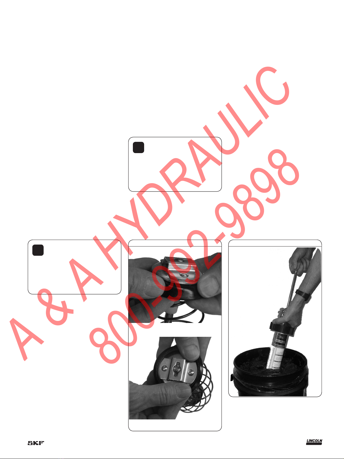
Prime the PowerLuber after each refill or
grease cartridge change. Prime the gun
before using it to lubricate grease points.
To prime, operate the gun until grease
flows from the hose. Use vent valve
(† fig. 1) to expel air pockets.
!Notice
To prevent damage to the gears in
the transmission, the motor must be
completely stopped before changing the
lever to the “L” or “H” (low or high) mode
of operation.
5
A & A HYDRAULIC
800-992-9898

Fig. 1
Vent
valve
Bulk
valve
Relief valve
discharge hole
Relief valve
1230
30 in.
(762 mm)
hose
5852 Coupler
with cap
Power
cord
6 ft. (1,8 m long)
High/low
output
sensor
Stroke
counter
6
A & A HYDRAULIC
800-992-9898

Install grease
cartridge
1 Unscrew the grease tube assembly from
the PowerLuber.
2 Visually check the follower seal lip
direction before loading a new cartridge.
The follower seal lip must be directed
toward the follower handle or rear side
for cartridge loading († Fig. 2).
(To change the direction of the follower
seal, unscrew tube cap from grease tube
assembly and pull on the handle to
remove follower seal from tube. Flip
follower seal over and reassemble.)
3 Pull back on the follower handle and latch
the follower rod groove into the slot on
the tube cap.
4 Remove the plastic cap from the grease
cartridge and insert cartridge into the
container tube.
5 Remove the pull tab from grease car-
tridge and screw grease tube assembly
into pump assembly.
6 Release follower rod from slot. Purge air
from pump. See air purging instructions.
Remove empty grease
cartridge
1 Pull back on the follower handle until the
follower rod is fully extended and latch the
follower rod groove into the slot on the
tube cap.
2 Unscrew the grease tube assembly from
the PowerLuber.
3 Carefully release the follower handle to
eject the empty cartridge from container
tube.
Fill gun from bulk
container
1 Remove pump assembly from grease
tube assembly.
2 Pack lubricant into cavity of the pump
assembly.
3 Insert the open end of the grease tube
assembly into lubricant († Fig. 3).
Slowly pull the follower handle back while
pushing the grease tube assembly deeper
into the lubricant to prevent air pockets
from being pulled into the grease tube
assembly.
4 When the follower rod is fully extended,
pull it sideways to latch the rod groove
into the keyhole slot in the grease tube
assembly cap.
5 Loosely assemble the pump assembly to
the grease tube assembly. Release the
follower rod from the grease tube assem-
bly cap and disengage the follower rod
from the follower by rotating the follower
handle. Push the follower rod into the
grease tube assembly. Slowly unscrew the
grease tube assembly from the pump
assembly until lubricant oozes from the
interface. Tighten grease tube assembly
into the pump assembly.
Convert gun to allow
filling from bulk
container or filler
pump
1 Unscrew the grease tube assembly cap
from the grease tube assembly. Pull on
the follower handle to extract the follower
and spring from the grease tube
assembly.
2 Grasp follower between thumb and fore-
finger and flip the follower lip from the
rear to the front side.
!Notice
The follower resembles a cup.
When the gun is assembled for use with
bulk lubricant, the cup opens toward the
pump assembly.
!Notice
Air pockets in the cartridge
lubricant will cause the gun to lose its
prime.
3 Reassemble follower into grease tube
assembly and position with the follower
handle so that the grease tube assembly
cap can be tightened onto the container
tube.
Fig. 2
Rear side
Front side
Fig. 3
7
A & A HYDRAULIC
800-992-9898

Fill gun with a filler
pump
1 Engage the follower rod with the follower
by rotating the follower handle.
2 Insert the gun vent/bulk fill valve into the
filler pump socket († fig. 4).
3
Operate the filler pump to fill the container.
When the follower rod groove is exposed,
the grease tube assembly is filled. The
follower rod will be extended
approximately 8 in. (20 cm). Do not
overfill!
4 Disengage the follower rod from the
follower by rotating the follower handle.
Fig. 4
Expel air pockets
1 Withdraw the follower rod from the
grease tube assembly cap and engage it
with the follower by rotating the follower
handle.
2 Unscrew the vent/bulk fill valve two turns.
Exert force on the follower handle until
grease flows through the opening in the
vent/bulk fill valve.
3 Tighten the vent/bulk fill valve.
4 Pull the trigger in short bursts to operate
gun until trapped air is expelled.
Disengage the follower rod from the
follower by rotating the follower handle.
Push the follower rod into the grease tube
assembly.
5 If step 2 fails, unscrew the grease tube
assembly 3 turns from the pump
assembly.
6 Exert force on the follower handle until
lubricant oozes from the grease tube
assembly and pump assembly interface.
7 Tighten grease tube assembly into the
pump assembly. Disengage the follower
rod from the follower by rotating the fol-
lower handle. Push the follower rod into
the grease tube assembly.
!Notice
Remove air pocket! Air pocket at
grease inlet will prevent grease from
being pumped. Unscrew the vent/bulk
fill valve two full turns to remove small
air pockets trapped in this area. If the air
pocket is substantial and no grease
flows from coupler after trigger is pulled
for 15 seconds, see the following steps.
5 Push the follower rod into the grease tube
assembly.
8
A & A HYDRAULIC
800-992-9898

1
3
4
2
5
6
7
89
10
11
12
8
14
15
16
18
19
20
17
13
Fig. 5
9
A & A HYDRAULIC
800-992-9898

Fig. 6
5
22
21 23 24
25
36
35
26
27
28
21
34
33
12 32
29
30
31
10
A & A HYDRAULIC
800-992-9898

Service parts list
Item Description Part number
1 Handle kit 286333
2 Follower assembly kit 93485
3 Packing 34793
4 Gasket kit (hose) 271884
5 Pump assembly kit 286334
6 Gear selector kit 286097
7 Stroke indicator 286108
8 Decal kit 286101
9 Seal rubber kit 286336
10 Trigger kit 286179
11 Cord protector kit 286157
12 Relief valve kit 286317
13 Grease tube assembly 271882
14 Cord kit 286156
15 Hose clip kit 286092
16 Handle kit (grease tube) 286090
17 Rod, follower kit 286091
18 Coupler cap kit 286093
19 Coupler 5852
20 Flexible hose 30 in. (762 mm) with gasket 1230
21 Gear set kit 286286
22 Motor & plate kit 286155
23 Spring selector 286113
24 Yoke kit 286107
25 Cover pump kit 286106
26 Plunger kit 286109
27 Seal 271889
28 Seal retainer kit 286335
29 Driver assembly 286285
30 Stud kit 286110
31 Roller kit 286111
32 Housing pump with bearing 286247*
33 Gasket kit (relief valve) 286316
34 Check valve kit 286306
35 Vent valve kit 286315
36 Vent/balk valve kit 286134
-- Hardware kit 286190
-- Strap 1414
-- Case 286240
*Indicates change.
11
A & A HYDRAULIC
800-992-9898

Troubleshooting
Condition Possible cause Corrective action
Motor fails to run. No power Check power cord connection with outlet.
Loose wire connection. Disassemble handle and check wiring for loose
connection.
Faulty switch. Replace switch.
Worn motor brushes. Replace motor.
Burned motor. Replace motor.
PowerLuber fails to dispense grease. Grease tube assembly is out of grease. Check that grease tube assembly has grease.
Loss of prime. Repeat priming operation.
Ball check item (34) is not functioning. Remove (34) and clean and inspect ball seat area.
PowerLuber continues to lose prime. Air may be trapped in several locations in container
after bulk filling.
Empty grease tube assembly, refill and repeat
priming instructions.
Follower may be binding in grease tube assembly. Replace grease tube assembly (13).
Disassemble grease tube assembly and clean.
Be sure that follower has properly entered the
grease cartridge.
Verify that the follower is not caught on the rim
of the grease cartridge.
12
A & A HYDRAULIC
800-992-9898

Lincoln industrial
standard warranty
Standard limited warranty
Lincoln warrants the equipment manufac-
tured and supplied by Lincoln to be free
from defects in material and workmanship
for a period of one (1) year following the
date of purchase, excluding there from any
special, extended, or limited warranty pub-
lished by Lincoln. If equipment is deter-
mined to be defective during this warranty
period, it will be repaired or replaced, within
Lincoln’s sole discretion, without charge.
This warranty is conditioned upon the
determination of a Lincoln authorized rep-
resentative that the equipment is defective.
To obtain repair or replacement, you must
ship the equipment, transportation charges
prepaid, with proof of purchase to a Lincoln
Authorized Warranty and Service Center
within the warranty period.
This warranty is extended to the original
retail purchaser only. This warranty does not
apply to equipment damaged from accident,
overload, abuse, misuse, negligence, faulty
installation or abrasive or corrosive material,
equipment that has been altered, or equip-
ment repaired by anyone not authorized by
Lincoln. This warranty applies only to equip-
ment installed, operated and maintained in
strict accordance with the written specifica-
tions and recommendations provided by
Lincoln or its authorized field personnel.
This warranty is exclusive and is in lieu
of any other warranties, express or
implied, including, but not limited to, the
warranty of merchantability or warranty
of fitness for a particular purpose. War-
ranty on items sold by Lincoln, but not
manufactured by Lincoln are subject to
the warranty consideration, if any, of
their manufacturer (such as hoses,
hydraulic and electric motors, electrical
controllers, etc.) Assistance in making
such warranty claims can be offered as
required.
In no event shall Lincoln be liable for inci-
dental or consequential damages. Lincoln’s
liability for any claim for loss or damages
arising out of the sale, resale or use of any
Lincoln equipment shall in no event exceed
the purchase price. Some jurisdictions do
not allow the exclusion or limitation of inci-
dental or consequential damages, therefore
the above limitation or exclusion may not
apply to you.
This warranty gives you specific legal
rights. You may also have other rights that
vary by jurisdiction.
Customers not located in the Western
Hemisphere or East Asia: Please contact
Lincoln GmbH and Co. Kg, Walldorf,
Germany, for your warranty rights.
Special limited warranties
Special limited 2 year warranty
SL-V series, single injectors–85772,
85782, and replacement injectors–85771,
85781
Lincoln warrants the SL-V Injector series to
be free from defects in material and work-
manship for two (2) years following the date
of purchase. If an injector model (single or
replacement) is determined to be defective
by Lincoln, in its sole discretion, during this
warranty period, it will be repaired or
replaced, at Lincoln’s discretion, without
charge.
Special limited 5 year warranty
series 20, 25, 40 bare pumps, pmv bare
pumps, heavy duty and 94000 series bare
reels
Lincoln warrants series 20, 25, 40 bare
pumps, PMV bare pumps, heavy duty
(82206), mini bench (81133, 81323), and
all 94000 LFR series (single arm and dual
arm) bare reels to be free from defects in
material and workmanship for five (5) years
following the date of purchase. If equipment
is determined by Lincoln, in its sole discre-
tion, to be defective during the first year of
the warranty period, it will be repaired or
replaced at Lincoln’s discretion, without
charge. In years two (2) and three (3), the
warranty on this equipment is limited to re-
pair with Lincoln paying parts and labor
only. In years four (4) and five (5), the war-
ranty on this equipment is limited to repair
with Lincoln paying for parts only.
Special limited 5 year warranty–
limited oil meters, limited fluid control
valves, aod (air-operated diaphragm
pumps)
Lincoln warrants the 712 series control
valves, 912 series lube meters, electronic
lube meters (980, 981, 982 series), our
universal inline digital meters (812/813
series), and our AOD pump offering to be
free from defects in material and workman-
ship for five (5) years following the date of
purchase. If either is determined to be
defective by Lincoln, in its sole discretion,
during the warranty period, they will be
repaired or replaced, at Lincoln’s discretion,
without charge.
Special DEF (diesel exhaust fluid) limited
warranty
DEF products are warranted to be free from
defects in material and workmanship for a
period of one (1) year following the date of
purchase. The following exceptions to the
standard warranty period are in effect:
• 85700-30/85700-50 DEF hose reels
(bare reel only),
277251/277252 AC DEF pumps, and
277256 and 277257 DEF meters are
warranted for two (2) years from date of
purchase.
• 85623 DEF AOD
(air operated diaphragm) pumps
are covered under the standard five (5)
year AOD pump warranty.
If either is determined to be defective by
Lincoln, in its sole discretion, during the
warranty period, they will be repaired or
replaced, at Lincoln’s discretion, without
charge.
Lincoln Industrial contact information
To find Lincoln Industrial’s nearest service
center call the following number;
customer service 314-679-4200
(international number 01-314-679-4200)
or you may also use our website
www.lincolnindustrial.com
13
A & A HYDRAULIC
800-992-9898

This page left intentionally blank
14
A & A HYDRAULIC
800-992-9898

This page left intentionally blank
15
A & A HYDRAULIC
800-992-9898

® SKF is a registered trademark of the SKF Group.
® Lincoln is a registered trademark of Lincoln Industrial Corp.
© SKF Group 2014
The contents of this publication are the copyright of the publisher and may not be reproduced (even extracts) unless prior written permis-
sion is granted. Every care has been taken to ensure the accuracy of the information contained in this publication but no liability can be
accepted for any loss or damage whether direct, indirect or consequential arising out of the use of the information contained herein.
SKF PUB LS/I4 14612 EN.R1 · April 2014 · Form 404575
Seals Bearings and
housings
Lubrication
systems
Mechatronics Services
The Power of Knowledge Engineering
Combining products, people, and application-
specific knowledge, SKF delivers innovative
solutions to equipment manufacturers and pro-
duction facilities in every major industry world-
wide. Having expert ise in multiple competence
areas supports SKF Life Cycle Management, a
proven approach to improv ing equipment reliabil-
ity, optimizing operational and energy efficiency
and reducing total cost of ownership.
These competence areas include bearings and
units, seals, lubrication systems, mecha tronics,
and awide range of services, from 3-D computer
modelling to cloud-based condition monitoring
and asset management services.
SKF’s global footprint provides SKF customers
with uniform quality standards and worldwide
product availability. Our local presence provides
direct access to the experience, knowledge and
ingenuity of SKF people.
SKF BeyondZero is more than our climate strategy
for a sustainable environment: it is our mantra; a
way of thinking, innovating and acting.
For us, SKF BeyondZero means that we will
reduce the negative environmental impact from
our own operations and at the same time, increase
the positive environmental contri bution by offering
our customers the SKF BeyondZero portfolio of
products and services with enhanced envir on-
mental performance characteristics.
For inclusion in the SKF BeyondZero portfolio,
aproduct, service or solution must deliver signifi-
cant environmental benefits without serious
envir onmental trade-offs.
C US
lincolnindustrial.com skf.com/lubrication
A & A HYDRAULIC
800-992-9898
This manual suits for next models
2
Table of contents
Other SKF Tools manuals
Popular Tools manuals by other brands

axing
axing BWZ 5-02 Operation instructions

Ingersoll-Rand
Ingersoll-Rand 2DA Series Operation and maintenance manual

Utility Solutions
Utility Solutions Jack Jumper USJJ-006 instruction manual

Tyco Electronics
Tyco Electronics 411-15684 instruction sheet

ERKCO
ERKCO 1000 user manual

Bosch
Bosch DLE 40 Professional Original instructions