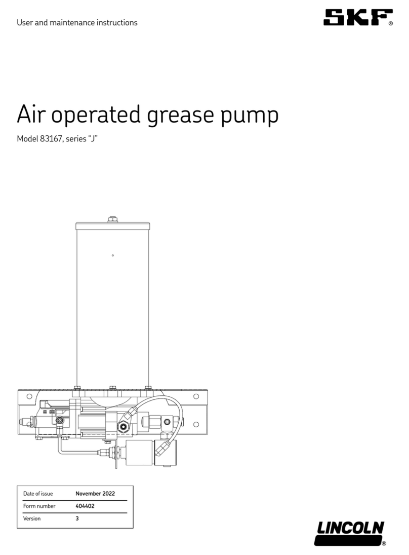
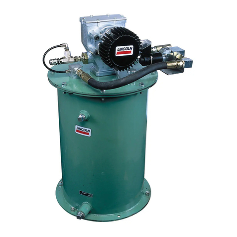
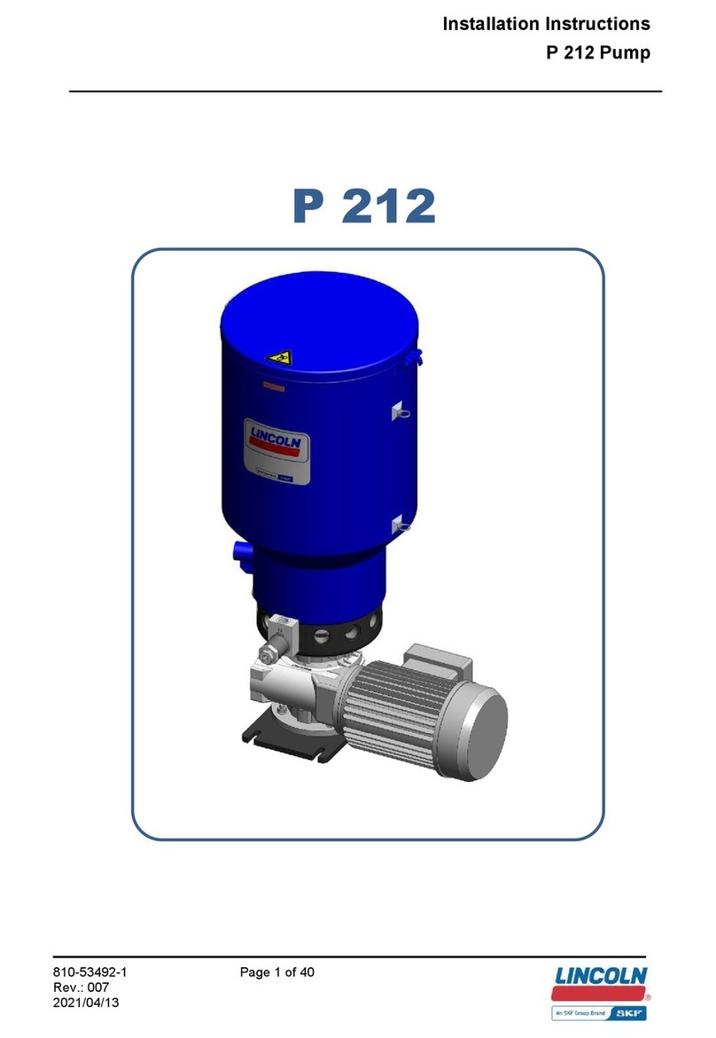
SKF P253 DC Smart User manual

Assembly Instructions
Lubricant feed pump P253 DC Smart
for progressive lubrication systems with Bluetooth
Created on:
01.08.2023
Document no.:
951-171-056-EN
Version:
04
Read these instructions before
installation or start
-up of the
product and keep
them readily
available for later consultation!

2
Original EC Declaration of Incorporation in accordance with Directive 2006/42/EC,
Appendix II Part 1 B
The manufacturer hereby declares at its sole responsibility that the partly completed machinery conforms to the essential health and safety requirements
of the Machinery Directive 2006/42/EC, Annex I, marked in the Annex to the EC Declaration of Incorporation as applicable and fulfilled at the time of placing
on the market.
The special technical documents were prepared following Annex VII part B. Upon justifiable request, these special technical documents can be forwarded
electronically to the respective national authorities. The authorized company for the compilation of the technical documentation is the manufacturer.
Designation:
Electrically operated pump P253 for the supply of lubricants within a centralized lubrication system
Type:
P253 Smart DC
Item number:
P253xx-xxxxxx-xxx-xx-xxxxxxxxxxxx-xxxxxx
6440-xxxxxxxx
Furthermore, the following directives and standards were applied in the respective applicable areas:
2006/42/EC: Machinery Directive
2011/65/EU: RoHS II
2014/53/EU: Radio Equipment Directive
EN ISO 12100:2010
EN 60204-1:2018
EN 809:1998+A1:2009/AC:2010
EN 61000-6-2:2005/AC:2005
EN 61000-6-4:2007/A1:2011
EN IEC 63000:2018
EN 301 489-1 v2.1.1
EN 301 489-17 v3.1.1
EN 300 328 v2.1.1
The partly completed machinery must not be put into service until it has been established that the machinery into which it is to be incorporated is in
compliance with the provisions of the Machinery Directive 2006/42/EC and all other applicable Directives.
Walldorf, 21.05.2021
Jürgen Kreutzkämper
Stefan Schürmann
Manager, R&D
Germany
Manager, PD
Germany South
Manufacturer: SKF Lubrication Systems Germany GmbH, Heinrich-Hertz-Str. 2-8, 69190 Walldorf, Germany
Original UK Declaration of incorporation according to the Supply of Machinery (Safety)
Regulations 2008 No. 1597 Annex II
The manufacturer hereby declares under sole responsibility that the partly completed machinery complies with the essential health and safety
requirements of UK legislation Supply of Machinery (Safety) Regulations 2008 No. 1597 Annex I, marked in the Annex to the EC Declaration of
Incorporation as applicable and fulfilled at the time of placing on the market.
The special technical documents were prepared following Annex VII part B. Upon justifiable request, these special technical documents can be forwarded
electronically to the respective national authorities. The authorized company for the compilation of the technical documentation is SKF (U.K.) Limited,
2 Canada Close, Banbury, Oxfordshire, OX16 2RT, GBR.
Designation:
Electrically operated pump P253 for the supply of lubricants within a centralized lubrication system
Type:
P253 Smart DC
Item number:
P253xx-xxxxxx-xxx-xx-xxxxxxxxxxxx-xxxxxx
6440-xxxxxxxx
Furthermore, the following regulations and standards were applied in the respective applicable areas:
Supply of Machinery (Safety) Regulations 2008 No. 1597
The Restriction of the Use of Certain Hazardous Substances in Electrical and Electronic Equipment Regulations 2012 No. 3032
Radio Equipment Regulations 2017 No. 1206
EN ISO 12100:2010
EN 60204-1:2018
EN 809:1998+A1:2009/AC:2010
EN 61000-6-2:2005/AC:2005
EN 61000-6-4:2007/A1:2011
EN IEC 63000:2018
EN 301 489-1 v2.1.1
EN 301 489-17 v3.1.1
EN 300 328 v2.1.1
The partly completed machinery must not be put into service until it has been established that the machinery into which it is to be incorporated is in
compliance with the provisions of UK legislation Supply of Machinery (Safety) Regulations 2008 No. 1597 and all other applicable Directives.
Walldorf, 21.05.2021
Jürgen Kreutzkämper
Stefan Schürmann
Manager, R&D
Germany
Manager, PD
Germany South
Manufacturer: SKF Lubrication Systems Germany GmbH, Heinrich-Hertz-Str. 2-8, 69190 Walldorf, Germany

3
Appendix to Declaration of Incorporation in accordance with 2006/42/EC, Annex II, No. 1 B
Description of the essential health and safety requirements according to 2006/42/EC, Annex I, which have been applied and fulfilled. Any
essential health and safety requirements not listed here are not relevant to this product.
Table 1
Appendix to Declaration of Incorporation
Valid for: P253 - lubricant feed pumps
No.:
Essential health and safety requirement
Applicable:
Fulfilled:
1.1.1
Definitions
Yes
Yes
1.1.2
Principles of safety integration
Yes
Yes
1.1.3
Materials and products
Yes
Partially1)
1.1.5
Design of machinery to facilitate its handling
Yes
Yes
1.1.6
Ergonomics
Yes
Partially2)
1.2
Control systems
Yes
Yes
1.2.1
Safety and reliability of control systems
Yes
Yes
1.2.3
Starting
Yes
Yes
1.2.6
Failure of the power supply
Yes
Yes
1.3
Protection against mechanical hazards
Yes
Yes
1.3.1
Risk of loss of stability
Yes
Yes
1.3.2
Risk of break-up during operation
Yes
Partially3)
1.3.4
Risks due to surfaces, edges or angles
Yes
Yes
1.3.7
Risks related to moving parts
Yes
Yes
1.3.9
Risks of uncontrolled movements
Yes
Yes
1.5
Risks due to other hazards
Yes
Yes
1.5.1
Electricity supply
Yes
Yes
1.5.6
Fire
Yes
Yes
1.5.8
Noise
Yes
Yes
1.5.11
External radiation
Yes
Yes
1.5.13
Emissions of hazardous materials and substances
Yes
Yes
1.5.15
Risk of slipping, tripping, or falling
Yes
Yes
1.6
Servicing
1.6.1
Machinery maintenance
Yes
Yes
1.6.2
Access to operating positions and servicing points
Yes
Partially4)
1.6.4
Operator interventions
Yes
Yes
1.7
Information
Yes
Yes
1.7.1
Information and warnings on the machinery
Yes
Yes
1.7.1.1
Information and information devices
Yes
Yes
1.7.2
Warning of residual risks
Yes
Yes
1.7.3
Marking of machinery
Yes
Yes
1.7.4
Operating instructions/assembly instructions
Yes
Yes
1.7.4.1
General principles for the drafting of operating instructions/assembly instructions
Yes
Yes
1.7.4.2
Contents of the operating instructions/assembly instructions
Yes
Yes
1.7.4.3
Sales literature
Yes
Yes
1) Not completely fulfilled: Hazards due to the lubricant used must be assessed by the operator on the basis of the Safety Data
Sheet (SDS) and, if necessary, protective measures must be taken.
2) Not completely fulfilled: The operator must ensure that the pump is integrated into the higher-level machine in such a way that
the pump can be operated and filled ergonomically.
3) Not completely fulfilled: The operator must protect the lubrication system against excessive pressure. For this purpose, a
pressure limiting valve with max. 270 bar opening pressure must be provided on each pump element.
4) Not completely fulfilled: The operator must ensure that the pump is integrated into the higher-level machine in such a way that
the pump can be operated without danger.

4
Masthead
Manufacturer
SKF Lubrication Systems Germany GmbH
Email: Lubrication-germany@skf.com
www.skf.com/lubrication
Berlin Plant
Motzener Strasse 35/37
12277 Berlin
Germany
Tel. +49 (0)30 72002-0
Fax +49 (0)30 72002-111
Walldorf Plant
Heinrich-Hertz-Strasse 2-8
69190 Walldorf, Germany
Germany
Tel.: +49 (0) 6227 33-0
Fax: +49 (0) 6227 33-259
Authorized local distributors
- Great Britain -
SKF (U.K.) Limited,
2 Canada Close, Banbury, Oxfordshire,
OX16 2RT, GBR.
- North America -
SKF Lubrication Business Unit
Lincoln Industrial
5148 North Hanley Road, St. Louis,
MO. 63134 USA
- South America -
SKF Argentina Pte. Roca 4145,
CP 2001 Rosario, Santa Fe
Warranty
The instructions contain no statements regarding the warranty
or liability for defects. That information can be found in our
General Terms of Payment and Delivery.
Training
We conduct detailed training in order to enable maximum
safety and efficiency. We recommend taking advantage of this
training. For further information, contact your authorized SKF
dealer or the manufacturer.

5
Table of contents
Masthead ...............................................................................................4
Table of contents..................................................................................5
Safety alerts, visual presentation, and layout.................................7
1. Safety instructions...........................................................................8
1.1 General safety instructions......................................................8
1.2 General electrical safety instructions.....................................8
1.3 General behaviour when handling the product ...................8
1.4 Intended use...............................................................................8
1.5 Persons authorized to use the product.................................8
1.6 Foreseeable misuse ..................................................................9
1.7 Referenced documents ............................................................9
1.8 Prohibition of certain activities ...............................................9
1.9 Painting plastic components and seals .................................9
1.10 Possible safety markings on the product ...........................9
1.11 Note on the type plate ........................................................10
1.12 Notes on CE marking .......................................................... 10
1.13 Note on Low Voltage Directive.......................................... 10
1.14 Note on Pressure Equipment Directive........................... 10
1.15 Note on ECE mark ...............................................................10
1.16 Note on UKCA marking....................................................... 10
1.17 Note on EAC marking..........................................................10
1.18 Note on China RoHS mark................................................. 10
1.19 Note on the wireless module............................................. 10
1.20 Emergency shutdown .........................................................10
1.21 Assembly, maintenance, fault, repair............................... 11
1.22 First start-up, daily start-up.............................................. 11
1.23 Residual risks........................................................................ 12
2. Lubricants ...................................................................................... 13
2.1 General information............................................................... 13
2.2 Material compatibility ............................................................ 13
2.3 Temperature properties........................................................13
2.4 Aging of lubricants .................................................................13
2.5 Avoidance of faults and hazards.......................................... 13
2.6 Solid lubricants ....................................................................... 13
2.7 Chisel pastes............................................................................13
3. Overview, functional description................................................ 14
3.1.1 Pumps without a follower plate .............................. 14
4. Technical data ............................................................................... 16
4.1 General technical data........................................................... 16
4.2 Nominal delivery rates ..........................................................17
4.2.1 Influencing factors on the delivery rate ................. 17
4.2.2 Delivery rate charts for typical NLGI 2 lubricants 18
4.3 Principle of operation of the intermittent low-level signal
.......................................................................................................... 19
4.4 Operational limits of the intermittent empty signal......... 20
4.5 Hydraulic connection diagrams ........................................... 21
4.6 Usable reservoir volume....................................................... 22
4.6.1 Usable reservoir volume for reservoirs without a
follower plate.........................................................................22
4.6.2 Usable reservoir volume for reservoirs with a
follower plate.........................................................................22
4.6.3 Usable reservoir volume for reservoirs with
double-lip follower plate ..................................................... 22
4.7 Lubricant volume when an empty pump is filled for the
first time.......................................................................................... 23
4.8 Tightening torques................................................................. 23
4.9 Type identification code.........................................................24
4.9.1 Basic parameters and reservoir design................. 24
4.9.2 Pump elements ..........................................................26
4.9.3 Voltage supply and electrical connections............. 27
4.9.4 Control and lubricant.................................................28
5. Delivery, returns, storage............................................................ 30
5.1 Delivery.....................................................................................30
5.2 Return shipment.....................................................................30
5.3 Storage.....................................................................................30
5.4 Storage temperature range .................................................30
5.5 Storage conditions for products filled with lubricant....... 30
5.5.1 Storage period up to 6 months............................... 30
5.5.2 Storage period between 6 and 18 months........... 30
5.5.3 Storage period more than 18 months...................30
5.6 Declaration of decontamination ..........................................30
6. Assembly ........................................................................................ 31
6.1 General safety instructions................................................... 31
6.2 Transporting the pumps .......................................................31
6.3 Mechanical connection ..........................................................32
6.3.1 Minimum mounting dimensions .............................32
6.3.2 Assembly holes........................................................... 34
6.3.3 Assembly holes for 15 l, 20 l, and 25 l reservoirs34
6.4 Electrical connection.............................................................. 36
6.5 Setting the delivery rate on pump element R or KR ....... 37
6.6 Installing the pressure limiting valve..................................38
6.7 Connection of the lubrication line........................................ 39
6.8 Filling with lubricant...............................................................39
6.8.1 Filling via the reservoir cover................................... 39
6.8.2 Filling via filler nipple................................................. 40
6.9 Initial filling of an empty pump with follower plate.......... 40
6.9.1 Initial filling with double-lip follower plate ............ 41
7. First start-up................................................................................. 42
7.1 Inspections before first start-up.......................................... 42
7.2 Inspections during first start-up..........................................42
8. Operation........................................................................................ 43
8.1 Top up lubricant .....................................................................43
8.2 Triggering additional lubrication ......................................... 43
9. Maintenance .................................................................................. 44
10. Cleaning ....................................................................................... 45
10.1 Basics .....................................................................................45
10.2 Interior cleaning ...................................................................45
10.3 Exterior cleaning ..................................................................45
11. Faults, causes, and remedies................................................... 46
12. Repairs ......................................................................................... 47
12.1 Replacing pump element and pressure limiting valve.. 47
13. Shutdown, disposal.................................................................... 48
13.1 Temporary shutdown..........................................................48
13.2 Permanent shutdown, disassembly .................................48
13.3 Disposal..................................................................................48
14. Spare parts.................................................................................. 49
14.1 Housing cover, complete ....................................................49
14.2 Pump elements................................................................... 49
14.3 Pressure limiting valves and adapters............................. 49
14.4 Adapter D6 AX 1/8NPT I C................................................. 50
14.5 Motor 12 / 24 V DC............................................................. 50
14.6 Adapter with filler nipple .................................................... 50

6
14.7 Closure screw........................................................................50
14.8 Transparent reservoir ..................................................... 5114.9 Fixed paddle ..........................................................................52
14.10 Reservoir cover ..................................................................52
14.11 Connection sockets and cables........................................52
15. Appendix.......................................................................................53
15.1.1 Terminal diagram for full and low-level signals on
the reservoir cover................................................................53
15.1.2 Terminal diagram for pump P253 DC Smart with
bayonet connector ................................................................54
15.1.3 Terminal diagram for pump P253 DC Smart with
rectangular connector and M12 connector .....................55
15.1.4 Overview of cables and possible connections.....56

7
Safety alerts, visual
presentation, and layout
While reading these instructions, you will encounter various
symbols, illustrations, and text layouts intended to help you
navigate and understand the instructions. Their meaning is
explained below.
Safety alerts:
Activities that present specific hazards (to life and limb or
possible damage to property) are indicated by safety alerts.
Always be sure to follow the instructions given in the safety
alerts.
<
DANGER
These safety alerts indicate an imminent danger.
Ignoring them will result in death or serious injury
<
WARNING
These safety alerts indicate potentially imminent
danger. Ignoring them could result in death or
serious injury
<
CAUTION
These safety alerts indicate potentially imminent
danger. Ignoring them could result in minor injury
<
NOTICE
These safety alerts indicate a potentially harmful
situation. Ignoring them could result in damage to
property or malfunctions
Illustrations:
The illustrations used depict a specific product. For other
products, they may have the function of a diagram only. This
does not alter the basic workings and operation of the product.
Text layout:
•First-order bulleted lists: Items on a bulleted list start with
a solid black dot and an indent.
–Second-order bulleted lists: If there is a further listing of
subitems, the second-order bulleted list is used.
1 Legend: A legend explains the numbered contents of an
illustration, presented as a numbered list. Items in a legend
start with a number (with no dot) and an indent.
–Second-order legend: In some cases, the numbered
contents of an image represent more than just one object.
A second-order legend is then used.
1.Instruction steps: These indicate a chronological sequence
of instruction steps. The numbers of the steps are in bold and
are followed by a period. If a new activity follows, the
numbering starts again at “1.”
–Second-order instruction steps: In some cases, it is
necessary to divide up a step into a few substeps. A
sequence of second-order instruction steps is then used.

8
1. Safety instructions
1.1 General safety instructions
•Putting the products into operation or operating them without
having read the instructions is prohibited. The operator must
ensure that the instructions are read and understood by all
persons tasked with working on the product or who supervise
or instruct such persons. Retain the instructions for further
use.
•The product may only be used in awareness of the potential
dangers, in proper technical condition, and according to the
information in this manual.
•Any faults that could affect safety must be remedied
according to responsibility. The supervisor must be notified
immediately in case of malfunctions outside one's individual
scope of responsibility.
•Unauthorized modifications and changes can have an
unpredictable effect on safety and operation. Unauthorized
modifications and changes are therefore prohibited. Only
original SKF spare parts and SKF accessories may be used.
•Any unclear points regarding proper condition or correct
assembly/operation must be clarified. Operation is prohibited
until issues have been clarified.
•The components used must be suitable for the intended use
and the applicable operating conditions, e.g. max. operating
pressure and ambient temperature range, and must not be
subjected to torsion, shear, or bending.
1.2 General electrical safety instructions
•Electrical devices must be kept in proper condition. This must
be ensured by periodic inspections in accordance with the
relevant applicable standards and technical rules. The type,
frequency, and scope of the inspections must be determined
in accordance with the risk assessment to be carried out by
the operator. Work on electrical components may be
performed only by qualified electricians. Connect the electrical
power only in accordance with the valid terminal diagram and
in observance of the relevant regulations and the local
electrical supply conditions.
•Work on electrical components may be performed only in a
voltage-free state and using tools suitable for electrical work.
Do not touch cables or electrical components with wet or
moist hands.
•Fuses must not be bridged. Always replace defective fuses
with fuses of the same type.
•Ensure proper connection of the protective conductor for
products with protection class I. Observe the specified
enclosure rating.
•The operator must implement appropriate measures to
protect vulnerable electrical devices from the effects of
lightning during use. The electrical device is not furnished
with a grounding system for the dissipation of the respective
electric charge and does not have the voltage strength
necessary to withstand the effects of lightning.
1.3 General behaviour when handling the
product
•Familiarize yourself with the functions and operation of the
product. The specified assembly and operating steps and their
sequences must be observed.
•Keep unauthorized persons away.
•Wear personal protective equipment always.
•Precautionary operational measures and instructions for the
respective work must be observed.
•In addition to these Instructions, general statutory regulations
for accident prevention and environmental protection must be
observed.
•Precautionary operational measures and instructions for the
respective work must be observed. Uncertainty seriously
endangers safety.
•Safety-related protective and safety equipment must not be
removed, modified or affected otherwise in its function and is
to be checked at regular intervals for completeness and
function.
•If protective and safety equipment has to be dismantled, it
must be reassembled immediately after finishing the work,
and then checked for correct function.
•Remedy occurring faults in the frame of responsibilities.
Immediately inform your superior in the case of faults beyond
your competence.
•Never use parts of the centralized lubrication system or of the
machine as standing or climbing aids.
1.4 Intended use
Supply of lubricants.
The product is intended solely for installation in another
machine.
Use is only permitted within the scope of commercial or
economic activity by professional users, in compliance with the
specifications, technical data, and limits specified in this manual.
1.5 Persons authorized to use the
product
Operator
A person who is qualified by training, knowledge and experience
to carry out the functions and activities related to normal
operation. This includes avoiding possible hazards that may
arise during operation.
Specialist in electrics
Person with appropriate professional education, knowledge and
experience to detect and avoid the hazards that may arise from
electricity.
Specialist in mechanics
Person with appropriate professional education, knowledge and
experience to detect and avoid the hazards that may arise
during transport, installation, start-up, operation, maintenance,
repair and disassembly.

9
1.6 Foreseeable misuse
Any usage of the product other than as specified in this manual
is strictly prohibited. Particularly prohibited are:
•Use of non-specified consumables, contaminated lubricants,
or lubricants with air inclusions.
•Use of C3 versions in areas with aggressive, corrosive
substances (e.g., high salt load).
•Use of plastic parts in areas with high exposure to ozone, UV
light, or ionizing radiation.
•Use to supply, convey, or store hazardous substances and
mixtures as defined in the CLP Regulation (EC 1272/2008) or
GHS with acute oral, dermal, or inhalation toxicity or
substances and mixtures that are marked with hazard
pictograms GHS01-GHS06 and GHS08.
•Use to supply, convey, or store Group 1 fluids classified as
hazards as defined in the Pressure Equipment Directive
(2014/68/EU) Article 13 (1) a).
•Use to supply, convey, or store gases, liquefied gases,
dissolved gases, vapors, or fluids whose vapor pressure
exceeds normal atmospheric pressure (1013 mbar) by more
than 0.5 bar at their maximum permissible operating
temperature.
•Use in an explosion protection zone.
•Use without proper securing against excessively high
pressures, in the case of pressurized products.
•Use outside of the technical data and limits specified in this
manual.
1.7 Referenced documents
In addition to this manual, the following documents must be
observed by the respective target group:
•Company instructions and approval rules
If applicable:
•Safety data sheet of the lubricant used
•Project planning documents
•Supplementary information regarding special designs of the
pump. This you will find in the special system documentation.
•Instructions for other components for setting up the
centralized lubrication system.
1.8 Prohibition of certain activities
The following activities must be performed only by employees of
the manufacturer or authorized persons due to possibly
undetectable sources of error or due to statutory requirements:
•Repairs or modifications to the drive
•Alterations to the control circuit board beyond adjustment of
lubrication times and interval times or replacement in case of
defect
1.9 Painting plastic components and
seals
The painting of any plastic components and seals of the
products described is prohibited. Completely mask or remove
plastic components before painting the main machine.
1.10 Possible safety markings on the
product
Fig. 1
Risk of dangerous electrical voltage (with VAC
products only)
Risk of being drawn into machinery by the
stirring paddle when the reservoir cover is
open
(only for reservoirs with filling from above)
Risk of injury from spring tension
(only in pumps with a follower plate)
Direction of rotation of the pump (stirring
paddle)
Read the instructions. Before initial filling of a
pump delivered without lubricant.
(Only for pumps with a double-lip follower
plate)
Possible safety markings on the product
NOTE
Further to the findings of the workplace risk evaluation the
operating company has to attach additional markings (e. g.
warnings, signs giving orders, prohibition signs or labelling
as specified by CLP / GHS), where appropriate.

10
1.11 Note on the type plate
The type plate provides important data such as the type
designation, order number, and sometimes regulatory
characteristics. To avoid loss of this data in case the type plate
becomes illegible, it should be entered in the manual.
Fig. 2
Type plate
Fig. 3
Type plate with ECE mark
1.12 Notes on CE marking
CE marking is effected following the requirements
of the applied directives requiring a CE marking:
•2014/53/EU Radio Equipment Directive (RED)
•2011/65/EU Directive on the restriction of the use of certain
hazardous substances in electrical and electronic equipment
(RoHS II)
1.13 Note on Low Voltage Directive
The protection objectives of the Low Voltage Directive
2014/35/EU are met in accordance with Annex I, No. 1.5.1 of
the Machinery Directive 2006/42/EC.
1.14 Note on Pressure Equipment
Directive
Due to its performance characteristics, the product does not
reach the limit values defined in Article 4, Paragraph 1,
Subparagraph (a) (ii) and is excluded from the scope of Pressure
Equipment Directive 2014/68/EU in accordance with Article 1,
Paragraph 2 Subparagraph (f).
1.15 Note on ECE mark
The ECE test mark (E1) confirms that an ECE
type approval (components requiring approval on
motor vehicles) has been granted for a product
which bears this mark on its type plate.
1.16 Note on UKCA marking
The UKCA conformity marking confirms the
product’s conformity with the applicable legal
provisions of Great Britain.
1.17 Note on EAC marking
The EAC conformity marking confirms the
product’s conformity with the applicable legal
provisions of the Eurasian customs union.
1.18 Note on China RoHS mark
The China RoHS mark confirms that there is no
danger to persons or the environment from the
regulated substances contained within for the
intended period of use (year number shown in the
circle).
1.19 Note on the wireless module
The wireless module installed in this product complies with the
requirements of the USA (FCC) and Canada (ISED). The
certification numbers can be found on the corresponding label
on the outside of the product.
Fig. 4
Wireless module certification number
NOTE
Note that the pump versions with Bluetooth can only be
operated in countries and regions for which the wireless
module is certified. You can check this
certification at skf.com/ or by scanning
the QR code shown here or the QR
code on the pump.
1.20 Emergency shutdown
This is done by a course of action to be defined by the operator.
SKF Lubrication Systems Germany GmbH
KW/JJ
Fact ory address
P253xx-xxxxxx-xxx-xx-xxxxxxxxxxxx-xxxxxx
Made in xxxxxxxxxxxxxx
Model:
P.No.:
S.No.:
6440-xxxxxxxx
xxxxxxxxxxxxxxx
pmax=
U=
P=
xxx bar / xxxx psi
xx VxC
xx W
SKF Lubrication Systems Germany GmbH
KW/JJ
Fact ory address
P253xx-xxxxxx-xxx-xx-xxxxxxxxxxxx-xxxxxx
Made in xxxxxxxxxxxxxx
Model:
P.No.:
S.No.:
6440-xxxxxxxx
xxxxxxxxxxxxxxx
xxx-xxxxxx
pmax=
U=
P=
xxx bar / xxxx psi
xx VxC
xx W

11
1.21 Assembly, maintenance, fault,
repair
Prior to the start of this work, all relevant persons must be
notified of it. At a minimum, the following safety measures must
be taken before any work is done:
•Unauthorized persons must be kept away
•Mark and secure the work area
•Cover adjacent live parts
•Dry any wet, slippery surfaces or cover them appropriately
•Cover hot or cold surfaces appropriately
Where applicable:
•Depressurize
•Isolate, lock and tag out
•Check to ensure live voltage is no longer present
•Ground and short-circuit
The product should be protected as much as possible from
humidity, dust, and vibration, and should be installed so that it
is easily accessible. Ensure an adequate distance from sources
of heat or cold. Any visual monitoring devices present, such as
pressure gauges, min./max. markings, or oil level gauges must
be clearly visible. Observe the mounting position requirements.
Drill required holes only on non-critical, non-load-bearing
parts of the operator's infrastructure. Use existing holes where
possible. Avoid chafe points. Immobilize any moving or detached
parts during the work. Adhere to the specified torques.
If guards or safety devices need to be removed, they must be
reinstalled immediately following conclusion of work and then
checked for proper function.
Check new parts for compliance with the intended use before
using them.
Avoid mixing up or incorrectly assembling disassembled parts.
Label parts. Clean any dirty parts.
1.22 First start-up, daily start-up
Ensure that:
•All safety devices are fully present and functional
•All connections are properly connected
•All parts are correctly installed
•All warning labels on the product are fully present, visible, and
undamaged
•Illegible or missing warning labels are immediately replaced

12
1.23 Residual risks
Table 2
Residual risks
Residual risk
Possible in lifecycle
Avoidance / Remedy
Personal injury / property damage due
to falling of hoisted parts.
A
B
C
G
H
K
Unauthorized persons must be kept away. Nobody is
allowed to be present below hoisted parts. Lift parts
using suitable lifting gear.
Personal injury / property damage due
to tilting or falling product due to non-
compliance with specified torques.
B
C
G
Adhere to the specified torques. Mount the product
only on components with a sufficient load-carrying
capacity. If no
torques are specified, use those specified
for the screw size for screws of strength class 8.8.
Personal injury, property damage due
to spilled, leaked lubricant.
B
C
D
F
G
H
K
Be careful when connecting or disconnecting the
lubricant lines. Use only hydraulic screw unions and
lubrication lines suitable for the specified pressure. Do
not mount lubrication lines on moving parts or chafe
points. If this cannot be avoided, use anti-kink coils
and/or conduits.
Fire hazard or damage to the pump
from operation with damaged electrical
components, such as power leads and
plugs.
B
C
D
E
F
G
H
Inspect electrical components for damage prior to
initial use and then at regular intervals. Do not install
the cable on moving parts or chafe points. If
this cannot
be avoided, use anti-kink coils and/or conduits.
Damage to the pump from failure to
comply with the permissible relative
ON-time.
C
D
Operate the pump only within the permissible relative
ON-time.
Damage to the pump from installing at
the place of use without the mounting
brackets and fastening hardware
intended for that purpose (see
Installation chapter).
B
C
D
G
Install the pump only with the mounting brackets and
fastening hardware intended for that purpose.
Lifecycle phases: A = Transport, B = Assembly, C = First start-up, D = Operation, E = Cleaning, F = Maintenance, G = Malfunction, repair, H
= Shutdown, K = Disposal

13
2. Lubricants
2.1 General information
Lubricants are selected specifically for the relevant application.
The manufacturer or operator of the machine should ideally
make the selection in consultation with the supplier of the
lubricant. If you have no or little experience in selecting
lubricants for lubrication systems, please contact us. We would
be happy to assist you in selecting suitable lubricants and
components to build a lubrication system optimized for your
particular application. Consider the following points when
selecting/using lubricants. This will spare you potential
downtime and damage to the machine or lubrication system.
2.2 Material compatibility
The lubricants must generally be compatible with the following
materials:
•Plastics: ABS, CR, FPM, NBR, NR, PA, PET, PMMA, POM, PP,
PS, PTFE, PU, PUR
•Metals: steel, gray cast iron, brass, copper, aluminum
2.3 Temperature properties
The lubricant used must be suitable for the specific ambient
temperature of the product. The viscosity approved for proper
functioning must neither be exceeded at low temperatures nor
fall too low at high temperatures. For the approved viscosity,
see the “Technical data” chapter.
2.4 Aging of lubricants
Based on past experience with the lubricant used, checks should
be conducted at regular intervals defined by the operator, to
determine whether the lubricant needs to be replaced due to
aging processes (oil separation). In case of doubt regarding the
continued suitability of the lubricant, it must be replaced before
the system is started up again. If you do not yet have any
experience with the lubricant used, we recommend conducting
a check after just one week.
2.5 Avoidance of faults and hazards
To avoid faults and hazards, please observe the following:
•When handling lubricants, observe the relevant safety data
sheet (SDS) and any hazard labeling on the packaging.
•Due to the large number of additives, some lubricants that
meet the pumpability requirements specified in the manual
are not suitable for use in centralized lubrication systems.
•Whenever possible, always use SKF lubrication greases. They
are ideal for use in lubrication systems.
•Do not mix lubricants. This can have unpredictable effects on
the properties and usability of the lubricant.
•Use lubricants containing solid lubricants only after technical
consultation with SKF.
• The lubricant’s ignition temperature has to be at least
50 kelvin above the maximum surface temperature of the
components.
2.6 Solid lubricants
Solid lubricants may only be used after prior consultation with
SKF. When solid lubricants are used in lubrication systems, the
following rules generally apply:
Graphite:
•Maximum graphite content 8%
•Maximum grain size 25 µm (preferably in lamellar form)
MoS2:
•Maximum MoS2 content 5%
•Maximum grain size 15 µm
Copper:
•Lubricants containing copper are known to lead to coatings
forming on pistons, bore holes, and mating surfaces. This can
result in blockages in the centralized lubrication system.
Calcium carbonate:
•Lubricants containing calcium carbonate are known to lead to
very heavy wear on pistons, bore holes, and mating surfaces.
Calcium hydroxide:
•Lubricants containing calcium hydroxide are known to harden
considerably over time, which can lead to failure of the
centralized lubrication system.
PTFE, zinc, and aluminum:
•For these solid lubricants, it is not yet possible to define any
limit values for use in lubrication systems on the basis of
existing knowledge and practical experience.
2.7 Chisel pastes
Due to their high resistance to pressure and temperature, chisel
pastes are used to reduce wear on insert tools and wear
bushings on hydraulic and pneumatic hammers, stone crushers
and hydraulic grabs. Before use, observe the safety data sheet
(SDS) and the technical data and application limits of the
respective chisel paste.
Chisel pastes may be pumped only with SKF pumps and
pump elements developed for this application.
Chisel pastes are special lubricants and must not be used as a
lubricant for bearings.
Grease guns filled with chisel paste must be permanently
marked with a corresponding note.
NOTE
The use of chisel paste requires prior consultation with the
SKF Product Management.

14
3. Overview, functional
description
3.1.1 Pumps without a follower plate
Fig. 5
Equipment features
Reservoir
The reservoir (Fig. 5/1) stores the lubricant. Different reservoir
designs and reservoir sizes exist in accordance with the pump
variant.
Reservoir cover
The reservoir cover (Fig. 5/2) is used to fill the reservoir with
clean and suitable lubricant, and also to protect the lubricant
from contamination.
Reservoir ventilation
The reservoir ventilation (Fig. 5/3) aerates the reservoir while
the pump is working and lubricant is being fed.
Pump housing
The pump housing (Fig. 5/4) contains the motor, the electrical
connections, the filler nipple, the pump elements, and (if
applicable) the intermittent low-level signal.
Pump elements
The pump can be equipped with up to 3 pump elements (Fig.
5/5).
Filler nipple
Used for filling the pump. If the filler nipple (Fig. 6/6) is
removed, the external grease return (from the pressure limiting
valves on the pump elements) can be connected to this port,
using the applicable accessories.
Fig. 6
Equipment features
Stirring paddle
The stirring paddle (Fig. 6/1) homogenizes and smooths the
lubricant while the pump is running.
In addition, the lower vertical part of the stirring paddle presses
the lubricant in the direction of the pump elements and
improves the suction characteristics of the pump as a result.

15
3.1.1.1 Electrical connections
Left-hand side:
•Rectangular connector (Fig. 7/1) for connecting the power
supply
•M12 connector, D-coded (Fig. 7/2) for connecting the LAN
Fig. 7
Electrical connections on the left
Right-hand side:
•Bayonet connector, 4/3-pin or 7/5-pin (Fig. 4/1)
for connecting a piston detector (4/3-pin) or for connecting 2
piston detectors (7/5-pin).
•Screwed gland, PG 9 (Fig. 4/2)
for connecting the low-level signal for pumps with a follower
plate
Fig. 8
Electrical connections on the right
3.1.1.2 Multifunction pushbutton (Fig. 9/1)
Triggering additional lubrication (Fig. 9/4)
Pressing the multifunction pushbutton briefly during the pause
time triggers an additional lubrication.
The pump runs until one metering device circulation is
complete, and then the pump goes back into the pause time.
Resetting a warning/error message (Fig. 9/4)
If there is an active warning (e.g., reservoir pre-empty signal) or
error message (reservoir empty, no signal from the piston
detector), it can be acknowledged and reset after remedying the
problem, by briefly pressing the multifunction pushbutton
during the pause time.
Ending the current operating time (Fig. 9/4)
Pressing the multifunction pushbutton while the pump is
running ends the current operating time. The pump is then in
pause time.
Indication of operating voltage (Fig. 9/1)
The indicator shows steady green light when sufficient
operating voltage is present.
Indication of warning or fault (Fig. 9/2)
In the case of a warning, the indicator flashes red at two-second
intervals. In the case of a fault (e.g., low-level signal), the
indicator shows a steady red light.
When the cause of the warning or fault is eliminated, the signal
must be reset by pressing the multifunction pushbutton (Fig.
9/4). When reset, the indicator light goes out.
Indication of Bluetooth (Fig. 9/3)
The indicator shows a blue light when a Bluetooth-enabled SKF
pump is connected to the SKF eLube app.
The SKF eLube app can be used to modify the pump settings
and to display operating data and Datalogger data. You can find
the SKF eLube app in the Apple App Store and the Google Play
Store.
Fig. 9
Multifunction pushbutton

16
4. Technical data
4.1 General technical data
Table 3
Technical data of the pump
Parameter
Values
Operating pressure
Max. 350 bar
Ambient temperature1)
-40 °C to 60 °C4)
-40 °C to 70 °C
Feedable lubricants2)
Lubricating greases up to and including NLGI 2, lubrication oils with at least
40
mm2/s (cST) at ambient temperature; for chisel paste, see the Lubricants
section
Pump elements
Max. 3
Mounting position3)
Upright, i.e., with the reservoir at top
Sound pressure level
< 70 dB (A)
ON-time
Max. 30 minutes
Pause time
Min. 3 times the ON-time
Electrical data of the pump
Parameter
Values
12 VDC pump
24 VDC pump
Enclosure rating5)
IP69K
IP69K
Protection classes
•
Rectangular connector / M12x1 connector
•Bayonet connector / PG9 screwed gland
SELV / PELV / FELV
SELV / PELV
SELV / PELV / FELV
SELV / PELV
Rated voltage ±10 %
12 VDC
24 VDC
Current input up to
6 A
3 A
Recommended back-up fuse
6.0 A (slow)
6.0 A (slow)
Motor operating voltage
12 VDC
24 VDC
Nominal speed
20 rpm
20 rpm
Cyclic duration factor6)
S3 25 % duty cycle 120 minutes
Output signal
Nonisolated
Nonisolated
Switching capacity, max.
60 VA
60 VA
Switching voltage, max.
30 VDC
30 VDC
Switched current, max.
700 mA
700 mA
1) The specified ambient temperature range requires that the lubricant used can be pumped at the given ambient temperature.
2) Observe the restrictions in the section “Operational limits of the intermittent empty signal.”
3) Rotary installation is possible for pumps with a follower plate, e.g., in wind turbines. Maximum speed and maximum distance to the
rotational axis can be specified on request. If the pump is expected to be installed in an inclined position: The maximum filling (“MAX”
mark) must be reduced in accordance with the inclination to be expected (e.g., with construction or agricultural machinery). The minimum
filling (“MIN” mark) must be increased starting with an expected inclination > 30°, otherwise functional impairments may arise due to a
reduced amount of lubricant the suction area of the pump.
4) UL-certified pumps can only be operated up to a maximum permissible ambient temperature of +60 °C regardless of the loading. In the
case of pumps that are not UL-certified, the maximum duty cycle should be reduced with ambient temperatures ≥ +60° C and heavy
loading (high pressure).
5) The specified enclosure rating of the pump requires the use of IP69K-compatible connection sockets and corresponding cables.
Classification is in accordance with the lowest enclosure rating when connection sockets and cables with low type of protection are used.
The achievable types of protection when using the connection sockets and cable which we supply can be found in the “Spare parts”
chapter.
6) Based on ambient temperature of 60 °C and a mean back pressure of 160 bar on the pump element.

17
Table 4
Factory setting for metering device circulations
Parameter
Values
Cycle time
6 hours
Metering device circulations:
1 metering device circulation per cycle time
Changes to the settings can be made with the SKF app for monitoring and adjusting Bluetooth-compatible SKF pumps. You can find
the SKF app in the Apple App Store and the Google Play Store. Following registration, use of the app is free of charge.
Weight
2-liter reservoir, standard filling (0.75 kg)
Approx. 6.5 kg
4-liter reservoir, standard filling (1.5 kg)
Approx. 9.0 kg
8-liter reservoir, standard filling (1.5 kg)
Approx. 10 kg
11-liter reservoir, standard filling (1.5 kg)
Approx. 12 kg
15-liter reservoir, standard filling (1.5 kg)
Approx. 14 kg
20-liter reservoir, standard filling (1.5 kg)
Approx. 16 kg
25-liter reservoir, standard filling (1.5 kg)
Approx. 18 kg
4.2 Nominal delivery rates
NOTE
The specified nominal delivery rates per stroke and pump element refer to NLGI grade 2 lubricating greases at an ambient
temperature of 20
°C [68 °F] and a back pressure of 100 bar [1450 psi] at the pump
element. Differences in operating conditions or a
different pump configuration will lead to changes in the motor speed and thus to a change in the delivery rate per unit of ti
me. If the
change in the motor speed necessitates an adjustment to the delivery r
ate per unit of time, then this will be reasonably accomplished
by adjusting the lubrication and pause time setting of the pump.
Table 5
Nominal delivery rate per stroke
Pump element
L1)
5
6
7
R
B
C2)
Nominal delivery rate per
stroke
0,03 ccm
0,10 ccm
0,16 ccm
0,22 ccm
0,04 - 0,18 ccm
0,10 ccm
0,24 ccm
1) With pump element L, lubricants below NLGI Grade 2 as specified in these instructions can be pumped without restriction.
2) The pump element “C” is designed only for pumping chisel paste. When using chisel paste, observe the relevant information in the
“Lubricants” section.
4.2.1 Influencing factors on the delivery rate
Table 6
Influencing factors on the delivery rate
Influencing factors
Increasing the delivery rate
Reducing the delivery rate
Ambient temperature
> + 20 °C
< + 20 °C
Consistency class of the lubricating grease
< NLGI 2
N/A
Number of pump elements
N/A
> 1
Back pressure at the pump element
< 100 bar
> 100 bar

18
4.2.2 Delivery rate charts for typical NLGI 2 lubricants
Fig. 10
Delivery rate chart for low-temperature grease
Fig. 11
Delivery rate chart for high-temperature grease
NOTE
The values specified in the delivery rate charts represent the average value between different high-temperature and low-temperature
greases. The values could therefore vary with the lubrication grease actually used in the pump. This may need to be borne in
mind
when designing the lubrication system.
Calculation of temperature-dependent delivery rate, using a high-temperature grease as an example
= ××
OUT
Calculated delivery rate per pump element (ccm/min)
RPM
Nominal speed of the pump (in this example: RPM = 20 rpm)
V
Nominal delivery rate per pump element (in this example: V = 0.22 ccm/stroke)
E
Efficiency as a percentage (in this example: E = 80%) at a temperature of T = -10 °C)
=20 1
× 0,22 ccm ×80 % = 3,5

19
4.3 Principle of operation of the
intermittent low-level signal
Components of the intermittent low-level signal
The intermittent low-level signal uses a contactless mechanism,
comprised essentially of the following parts:
•Stationary reed switch (Fig. 12 to 14/1) in the reservoir
bottom
•Mobile baffle plate (Fig. 12 to 13/2) connected to the stirring
paddle, with a magnet (Fig. 12 to 14/3) and a cam (Fig. 13/4)
Fig. 12
Perspective view
Functional description of the intermittent low-level signal
1 When the reservoir is filled with a lubrication grease that is
suitable for the intermittent low-level signal, and the pump is
running, the baffle plate (Fig. 12 to 13/2) is deflected
outwards by the resistance of the lubrication grease.
2 As a result, the magnet (Fig. 12 to 14/3) connected to the
baffle plate moves along its inner circular path (Fig. 13), which
means that it cannot trigger a pulse on the reed switch
(Fig. 12 to 14/1).
3 During each revolution, a cam (Fig. 13/4) forces the magnet
and the pivot-mounted baffle plate back out onto the outer
circular path (Fig. 14)
4 After passing the cam, the resistance of the lubricant pushes
the baffle plate and the magnet back inwards, onto the inner
circular path.
Fig. 13
Magnet on inner circular path
5 When the lubricant level in the reservoir drops so far that the
resistance of the lubrication grease is no longer enough to
deflect the baffle plate (Fig. 12 to 13/2), the magnet
(Fig. 12 to 14/3) stays on the outer path, triggering a pulse
during each revolution as it slides over the reed switch
(Fig. 12 to 14/1).
6 If the magnet (Fig. 12 to 14/3) moves over the reed switch
(Fig. 12 to 14/1) on the outer circular path six times during
one work cycle, a low-level signal is output directly on the
pump's signal connection.
Fig. 14
Magnet on outer circular path

20
4.4 Operational limits of the intermittent empty signal
For the correct functioning of the intermittent empty signal, the following lubricant consistencies must be maintained. The correct
functioning of the intermittent empty signal is not guaranteed above the specified temperature range. The lower temperature ranges are
contingent on the suitability of the respective lubricant for these temperatures. Excessively high consistency of the lubricant could
otherwise lead to malfunctions such as interruption of the lubricant feeding or possibly to damage to the pump (e.g., bending of the
stirring paddle).
NOTE
The intermittent empty signal is not suitable for lubricating greases with an NLGI class ≤ 0.
Fig. 15
Operational limits of the intermittent empty signal
Table of contents
Other SKF Water Pump manuals

SKF
SKF 40PGA User manual

SKF
SKF LAGG Series User manual

SKF
SKF LINCOLN SP User manual

SKF
SKF LINCOLN P623S User manual

SKF
SKF Lincoln PFHM-EEX User manual

SKF
SKF ECP User manual

SKF
SKF MityVac MV7201 Instruction Manual

SKF
SKF K Series Instruction Manual

SKF
SKF Linkoln Pile Driver III C Series Instruction Manual

SKF
SKF F Series Instruction Manual
Popular Water Pump manuals by other brands

Ingersoll-Rand
Ingersoll-Rand PD10X-X-X Operator's manual

Grundfos
Grundfos ALPHA Installation and operating instructions

Pfeiffer Vacuum
Pfeiffer Vacuum Pascal Series operating instructions

SAMES KREMLIN
SAMES KREMLIN REXSON SH0207 user manual

Grundfos
Grundfos UPN Series instructions

Becker
Becker VariAir VASF 2.50/1-0.AC230 operating instructions