Skil 5680 Assembly instructions

IMPORTANT: IMPORTANT : IMPORTANTE:
Read Before Using Lire avant usage Leer antes de usar
For English Version Version française Versión en español
See page 2 Voir page 14 Ver la página 26
Operating/Safety Instructions
Consignes de fonctionnement/sécurité
Instrucciones de funcionamiento y seguridad
1-877-SKIL999 (1-877-754-5999) www.skil.com
Call Toll Free for
Consumer Information
&Service Locations
Pour obtenir des informations
et les adresses de nos centres
de service après-vente,
appelez ce numéro gratuit
Llame gratis para
obtener información
para el consumidor y
ubicaciones de servicio
5680
SM 1619X02967 05-08 4/30/08 11:34 AM Page 1

-2-
Work area safety
Keep work area clean and well lit.
Cluttered or dark areas invite accidents.
Do not operate power tools in explosive
atmospheres, such as in the presence of
flammable liquids, gases or dust. Power
tools create sparks which may ignite the dust
or fumes.
Keep children and bystanders away while
operating a power tool. Distractions can
cause you to lose control.
Electrical safety
Power tool plugs must match the outlet.
Never modify the plug in any way. Do not
use any adapter plugs with earthed
(grounded) power tools. Unmodified plugs
and matching outlets will reduce risk of
electric shock.
Avoid body contact with earthed or
grounded surfaces such as pipes,
radiators, ranges and refrigerators. There
is an increased risk of electric shock if your
body is earthed or grounded.
Do not expose power tools to rain or wet
conditions. Water entering a power tool will
increase the risk of electric shock.
Do not abuse the cord. Never use the cord
for carrying, pulling or unplugging the
power tool. Keep cord away from heat, oil,
sharp edges or moving parts. Damaged or
entangled cords increase the risk of electric
shock.
When operating a power tool outdoors,
use an extension cord suitable for
outdoor use. Use of a cord suitable for
outdoor use reduces the risk of electric
shock.
Do not use AC only rated tools with a DC
power supply. While the tool may appear to
work, the electrical components of the AC
rated tool are likely to fail and create a
hazard to the operator.
If operating the power tool in damp
locations is unavoidable a Ground Fault
Circuit Interrupter (GFCI) must be used to
supply the power to your tool. GFCI and
personal protection devices like electrician’s
rubber gloves and footwear will further
enhance your personal safety.
Personal safety
Stay alert, watch what you are doing and
use common sense when operating a
power tool. Do not use a power tool while
you are tired or under the influence of
drugs, alcohol or medication. Amoment of
inattention while operating power tools may
result in serious personal injury.
Use safety equipment. Always wear eye
protection. Safety equipment such as dust
mask, non-skid safety shoes, hard hat, or
hearing protection used for appropriate
conditions will reduce personal injuries.
Avoid accidental starting. Ensure the
switch is in the off-position before
plugging in. Carrying power tools with your
finger on the switch or plugging in power
tools that have the switch on invites
accidents.
Remove any adjusting key or wrench
before turning the power tool on. Awrench
or a key left attached to a rotating part of the
power tool may result in personal injury.
Do not overreach. Keep proper footing
and balance at all times. This enables
better control of the power tool in unexpected
situations.
Dress properly. Do not wear loose
clothing or jewelry. Keep your hair,
clothing and gloves away from moving
parts. Loose clothes, jewelry or long hair can
be caught in moving parts.
If devices are provided for the connection
of dust extraction and collection facilities,
ensure these are connected and properly
used. Use of these devices can reduce dust-
related hazards.
Keep handles dry, clean and free from oil
and grease. Slippery hands cannot safely
control the power tool.
Read all instructions. Failure to follow all instructions listed below may
result in electric shock, fire and/or serious injury. The term “power tool” in
all of the warnings listed below refers to your mains-operated (corded) power tool or battery-
operated (cordless) power tool.
SAVE THESE INSTRUCTIONS
!
WARNING
General Safety Rules
SM 1619X02967 05-08 4/30/08 11:34 AM Page 2

-3-
Safety Rules for Circular Saws
Cutting procedures
Keep hands away from
cutting area and blade.
Keep your second hand on auxiliary
handle, or motor housing. If hands are
holding the saw, they cannot be cut by the
blade.
Adjust the cutting depth to the thickness of
the workpiece. Less than a full tooth of the
blade teeth should be visible below the
workpiece.
Do not reach underneath the workpiece.
The guard cannot protect you from the blade
below the workpiece.
NEVER hold piece being cut in your hands
or across your leg. Secure the workpiece to
stable platform. It is important to support the
work properly to minimize body exposure,
blade binding, or loss of control.
Hold power tool by the insulated gripping
surfaces when performing an operation
where the cutting tool may contact hidden
DANGER
!
Power tool use and care
Do not force the power tool. Use the
correct power tool for your application.
The correct power tool will do the job better
and safer at the rate for which it was
designed.
Do not use the power tool if the switch
does not turn it on and off. Any power tool
that cannot be controlled with the switch is
dangerous and must be repaired.
Disconnect the plug from the power
source and/or the battery pack from the
power tool before making any
adjustments, changing accessories, or
storing power tools. Such preventive safety
measures reduce the risk of starting the
power tool accidentally.
Store idle power tools out of the reach of
children and do not allow persons
unfamiliar with the power tool or these
instructions to operate the power tool.
Power tools are dangerous in the hands of
untrained users.
Maintain power tools. Check for
misalignment or binding of moving parts,
breakage of parts and any other condition
that may affect the power tools operation.
If damaged, have the power tool repaired
before use. Many accidents are caused by
poorly maintained power tools.
Keep cutting tools sharp and clean.
Properly maintained cutting tools with sharp
cutting edges are less likely to bind and are
easier to control.
Use the power tool, accessories and tool
bits etc., in accordance with these
instructions and in the manner intended
for the particular type of power tool,
taking into account the working
conditions and the work to be performed.
Use of the power tool for operations different
from those intended could result in a
hazardous situation.
Use clamps or other practical way to
secure and support the workpiece to a
stable platform. Holding the work by hand
or against your body is unstable and may
lead to loss of control.
Service
Have your power tool serviced by a
qualified repair person using only identical
replacement parts. This will ensure that the
safety of the power tool is maintained.
Develop a periodic maintenance schedule
for your tool. When cleaning a tool be
careful not to disassemble any portion of
the tool since internal wires may be
misplaced or pinched or safety guard
return springs may be improperly
mounted. Certain cleaning agents such as
gasoline, carbon tetrachloride, ammonia, etc.
may damage plastic parts.
Risk of injury to user, power cord must only be
serviced by a Skil Factory Service Center or
Authorized Skil Service Station.
SAVE THESE INSTRUCTIONS
Read all safety warnings and all instructions.
!
WARNING
SM 1619X02967 05-08 4/30/08 11:34 AM Page 3

wiring or it own cord. Contact with a "live" wire
will also make exposed metal parts of the tool
“live” and shock the operator.
When ripping always use a rip fence or
straight edge guide. This improves accuracy
of cut and reduces the chance for blade
binding.
Always use blades with correct size and
shape (diamond vs. round) of arbor holes.
Blades that do not match the mounting
hardware of the saw will run eccentrically,
causing loss of control.
Never use damaged or incorrect blade
washers or bolts. The blade washers and bolt
were specially designed for your saw, for
optimum performance and safety of operation.
Inspect the condition and quality of the
wood and remove all nails from lumber
before cutting. Wet lumber, green lumber or
pressure treated lumber require special
attention during cutting operation to prevent
kickback.
Hold the saw firmly to prevent loss of
control. Figures in this manual illustrate
typical hand support of the saw.
Depending upon use, the switch may not
last the life of the saw. If the switch should
fail in the “OFF” position, the saw may not
start. If it should fail while the saw is
running, the saw may not shut off. If either
occurs, unplug the saw immediately and do not
use until repaired.
This circular saw should not be mounted to
atable and converted to a table saw.
Circular saws are not designed or intended to
be used as table saws.
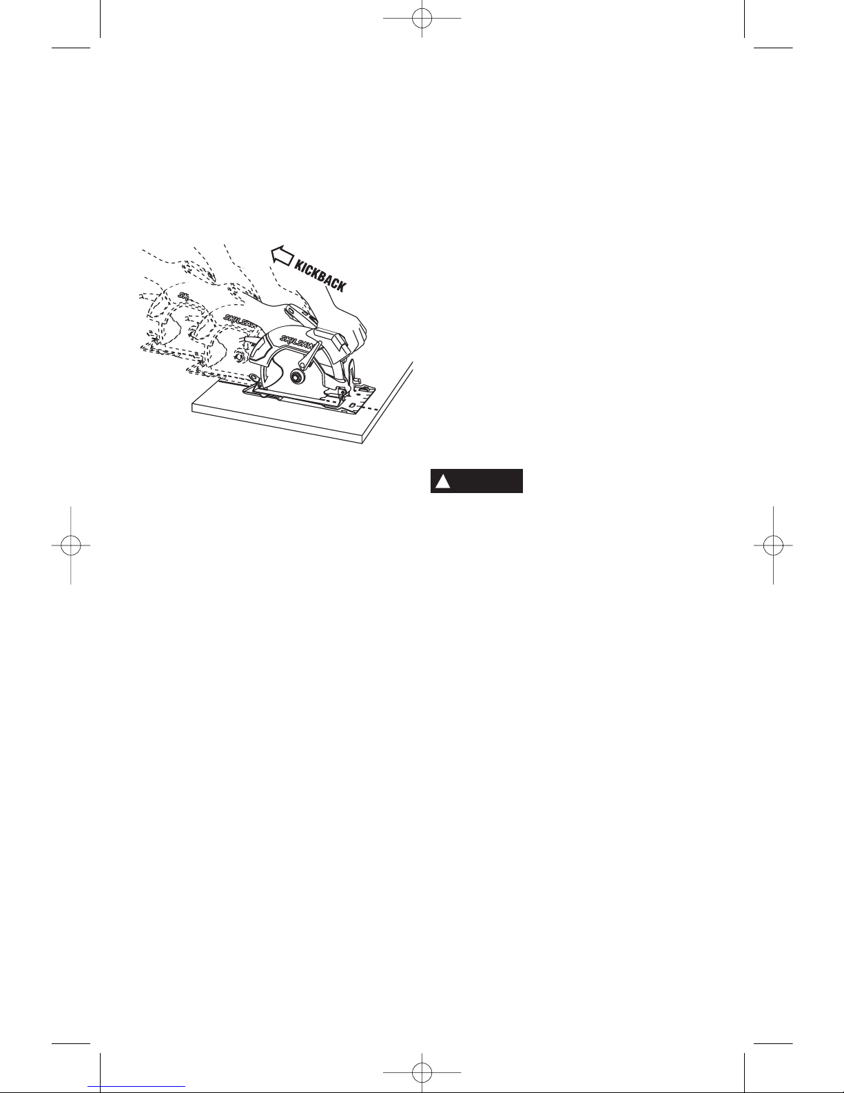
Kickback and related warnings
Causes and operator prevention of
kickback:
Kickback is a sudden reaction to a pinched,
bound or misaligned saw blade, causing an
uncontrolled saw to lift up and out of the
workpiece toward the operator.
When the blade is pinched or bound tightly by
the kerf closing down, the blade stalls and the
motor reaction drives the unit rapidly back
toward the operator.
If the blade becomes twisted or misaligned in
the cut, the teeth at the back edge of the blade
can dig into the top surface of the wood
causing the blade to climb out of the kerf and
jump back toward the operator.
Kickback is the result of tool misuse and/or
incorrect operating procedures or conditions
and can be avoided by taking proper
precautions as given below:
Maintain a firm grip with both hands on the
saw and position your body and arm to
allow you to resist kickback forces.
Position your body to either side of the
blade, but not in line with the blade.
Kickback could cause the saw to jump
backwards, but kickback forces can be
controlled by the operator, if proper
precautions are taken.
When blade is binding, or when interrupting
acut for any reason, release the trigger and
hold the saw motionless in the material
until the blade comes to a complete stop.
Never attempt to remove the saw from the
work or pull the saw backward while the
blade is in motion or kickback may occur.
Investigate and take corrective action to
eliminate the cause of blade binding.
When restarting a saw in a workpiece,
center the saw blade in the kerf and check
that saw teeth are not engaged into the
material. If saw blade is binding, it may walk
up or kickback from the workpiece as the saw
is restarted.
Support large panels to minimize the risk of
blade pinching and kickback. Large panels
tend to sag under their own weight. Supports
must be placed under the panel on both sides,
near the line of cut and near the edge of the
panel.
Do not use dull or damaged blade.
Unsharpened or improperly set blades
produce narrow kerf causing excessive friction,
blade binding and kickback.
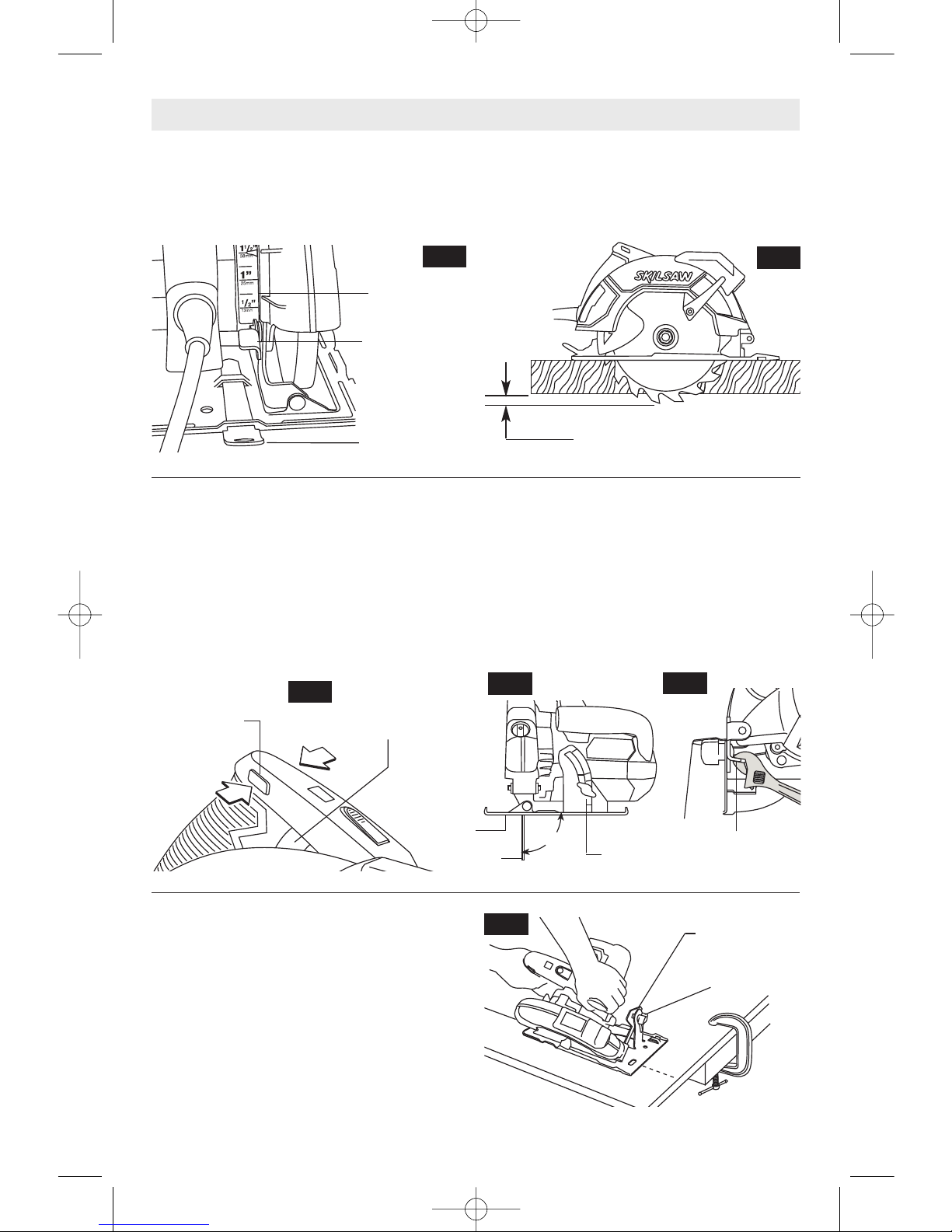
Blade depth and bevel adjusting locking
levers must be tight and secure before
making cut. If blade adjustment shifts while
cutting, it may cause binding and kickback.
Use extra caution when making a “Plunge
Cut” into existing walls or other blind
areas. The protruding blade may cut objects
that can cause kickback.
The blade washers and the bolt on your
saw have been designed to work as a
clutch to reduce the intensity of a kickback.
Understand the operation and settings of
the VARI-TORQUE CLUTCH. The proper
setting of the clutch, combined with firm
handling of the saw will allow you to control
kickback.
-4-
SM 1619X02967 05-08 4/30/08 11:34 AM Page 4

Never place your hand behind the saw
blade. Kickback could cause the saw to jump
backwards over your hand.
Donot use the saw with an excessive
depth of cut setting. Too much blade
exposure increases the likelihood of the blade
twisting in the kerf and increases the surface
area of the blade available for pinching that
leads to kickback.
Lower guard function
Check lower guard for proper closing
before each use. Do not operate saw if
lower guard does not move freely and
close instantly. Never clamp or tie the lower
guard into the open position. If saw is
accidentally dropped, lower guard may be
bent. Raise the lower guard only with the
Lower Guard Lift Lever and make sure it
moves freely and does not touch the blade or
any other part, in all angles and depths of cut.
Check the operation of the lower guard
spring. If the guard and the spring are not
operating properly, they must be serviced
before use. Lower guard may operate
sluggishly due to damaged parts, gummy
deposits, or a buildup of debris.
Lower guard should be retracted manually
only for special cuts such as “Plunge Cuts”
and “Compound Cuts”. Raise lower guard
bylower guard Lift lever and as soon as
blade enters the material, lower guard must
be released. For all other sawing, the lower
guard should operate automatically.
Always observe that the lower guard is
covering the blade before placing saw
down on bench or floor. An unprotected,
coasting blade will cause the saw to walk
backwards, cutting whatever is in its path. Be
aware of the time it takes for the blade to stop
after switch is released.
Do not run the tool while carrying it at your
side. Lower guard may be opened by a
contact with your clothing. Accidental
contact with the spinning saw blade could
result in serious personal injury.
Periodically remove the blade, clean the
upper, lower guards and the hub area with
kerosene and wipe it dry, or blow it clean
with compressed air. Preventive maintenance
and properly operating guard will reduce the
probability of an accident.
Some dust created by
power sanding, sawing,
grinding, drilling, and other construction
activities contains chemicals known to
cause cancer, birth defects or other
reproductive harm. Some examples of
these chemicals are:
•Lead from lead-based paints,
•Crystalline silica from bricks and cement and
other masonry products, and
•Arsenic and chromium from chemically-
treated lumber.
Your risk from these exposures varies,
depending on how often you do this type of
work. To reduce your exposure to these
chemicals: work in a well ventilated area, and
work with approved safety equipment, such as
those dust masks that are specially designed
to filter out microscopic particles.
-5-
!
WARNING
SM 1619X02967 05-08 4/30/08 11:34 AM Page 5

-6-
IMPORTANT: Some of the following symbols may be used on your tool. Please study them
and learn their meaning. Proper interpretation of these symbols will allow you to operate the
tool better and safer.
Symbol Name Designation/Explanation
V Volts Voltage (potential)
A Amperes Current
Hz Hertz Frequency (cycles per second)
W Watt Power
kg Kilograms Weight
min Minutes Time
s Seconds Time
Diameter Size of drill bits, grinding wheels, etc.
n0No load speed Rotational speed, at no load
.../min Revolutions or reciprocation per minute Revolutions, strokes, surface speed,
orbits etc. per minute
0 Off position Zero speed, zero torque...
1, 2, 3, ... Selector settings Speed, torque or position settings.
I, II, III, Higher number means greater speed
Infinitely variable selector with off Speed is increasing from 0 setting
Arrow Action in the direction of arrow
Alternating current Type or a characteristic of current
Direct current Type or a characteristic of current
Alternating or direct current Type or a characteristic of current
Class II construction Designates Double Insulated
Construction tools.
Earthing terminal Grounding terminal
Warning symbol Alerts user to warning messages
Ni-Cad RBRC seal Designates Ni-Cad battery recycling
program
Symbols
0
This symbol designates
that this tool is listed by
Underwriters Laboratories.
This symbol designates
that this tool is listed by
the Canadian Standards
Association.
This symbol designates
that this tool is listed to
Canadian Standards by
Underwriters Laboratories. This symbol
designates
that
this tool
complies
to NOM
Mexican
Standards.
This symbol designates that
this tool is listed by
Underwriters Laboratories,
and listed to Canadian
Standards by Underwriters
Laboratories.
SM 1619X02967 05-08 4/30/08 11:34 AM Page 6

-7-
Functional Description and Specifications
Disconnect the plug from the power source before making any
assembly, adjustments or changing accessories.Such preventive safety
measures reduce the risk of starting the tool accidentally.
!
WARNING
FIG. 1
LOWER
GUARD
FOOT
LOWER GUARD
LIFT LEVER
AUXILIARY
HANDLE
BEVEL
ADJUSTMENT
KNOB
CALIBRATED
BEVEL
QUADRANT
SAFETY SWITCH
UPPER
GUARD
Maximum Capacities
Blade 7-1/4"
Blade arbor hole Round Depth of cut at 90°2-7/16"
Depth of cut at 45° 1-15/16"
Circular Saw
DEPTH
ADJUSTMENT
LEVER
DEPTH SCALE
NOTE: For tool specifications refer to the nameplate on your tool.
LASER BUTTON
POWER INDICATOR LIGHT
BLADE WRENCH,
&STORAGE AREA
SM 1619X02967 05-08 4/30/08 11:34 AM Page 7

-8-
Assembly
ATTACHING THE BLADE
Disconnect the plug from
the power source before
making any assembly, adjustments or
changing accessories.Such preventive
safety measures reduce the risk of starting
the tool accidentally.
1. Turn BLADE STUD with wrench provided
counter-clockwise and remove BLADE STUD
and OUTER WASHER (Fig. 2). If the shaft
moves while attempting to loosen the blade
stud, strike the wrench counter-clockwise to jar
BLADE STUD loose.
2. Retract the lower guard all the way up into
the upper guard. While retracting the lower
guard, check operation and condition of the
LOWER GUARD SPRING.
3. Make sure the saw teeth and arrow on the
blade point in the same direction as the arrow
on the lower guard.
4. Slide blade through slot in the foot and
mount it against the INNER WASHER on the
shaft. Be sure the large diameter of the OUTER
washer lays flush against the blade.
5. Reinstall OUTER WASHER and tighten
BLADE STUD finger tight. To lock shaft hold
the saw securely by the upper guard with
blade teeth imbedded in scrap wood and
TIGHTEN BLADE STUD 1/8 TURN (45°)
WITH THE WRENCH PROVIDED.
Do not use wrenches with longer handles,
since it may lead to over tightening of the blade
stud. VARI-TORQUE CLUTCH
This clutching action is provided by the friction
of the OUTER WASHER against the BLADE
and permits the blade shaft to turn when the
blade encounters excessive resistance. When
the BLADE STUD is properly tightened (as
described in No. 5 of Attaching The Blade), the
blade will slip when it encounters excessive
resistance, thus reducing saw’s tendency to
KICKBACK.
One setting may not be sufficient for cutting all
materials. If excessive blade slippage occurs,
tighten the blade stud a fraction of a turn more
(less than 1/8 turn). OVERTIGHTENING THE
BLADE STUD NULLIFIES THE EFFECTIVE-
NESS OF THE CLUTCH.
!
WARNING
FIG. 2
Tighten
Loosen
BLADE
STUD
LOWER GUARD
SPRING
OUTER WASHER
Large Diameter
Faces Blade
INNER WASHER
Large Diameter
Faces Blade
BLADE
LOWER
GUARD
BLADE SHAFT
UPPER GUARD
SM 1619X02967 05-08 4/30/08 11:34 AM Page 8

-9-
DEPTH ADJUSTMENT
Disconnect plug from power source. Loosen
the depth adjustment lever located between
the guard and handle of saw. Hold the foot
down with one hand and raise or lower saw by
the handle. Tighten lever at the depth setting
desired. Check desired depth (Fig. 3).
Not more than one tooth length of the blade
should extend below the material to be cut, for
minimum splintering (Fig. 4).
SAFETY SWITCH
The safety switch is designed to prevent
accidental starts. To operate safety switch,
press the release button with your thumb on
either side of handle to disengage the lock,
then pull the trigger (Fig. 5). When the trigger
is released the button will engage the safety
switch automatically, and the trigger will no
longer operate. (See Switch & General Cuts
on page 10.)
90° CUTTING ANGLE CHECK
Disconnect plug from power source. Set foot
to maximum depth of cut setting. Loosen
bevel adjustment knob, set to 0° on quadrant,
retighten knob and check for 90° angle
between the blade and bottom plane of foot
with a square (Fig. 6). If adjustment is
necessary, tilt foot to 45°,tighten bevel
adjustment knob and bend "TAB" with an
adjustable wrench or pliers (Fig. 7).
BEVEL ADJUSTMENT
Disconnect plug from power source. The foot
can be adjusted up to 45° by loosening the
bevel adjustment knob at the front of the saw.
Align to desired angle on calibrated quadrant.
Then tighten bevel adjustment knob (Fig. 8).
Because of the increased amount of blade
engagement in the work and decreased
stability of the foot, blade binding may occur.
Keep the saw steady and the foot firmly on the
workpiece.
Operating Instructions
90º
FIG. 3 FIG. 4
FIG. 5 FIG. 7
FIG. 6
FIG. 8
ONE TOOTH LENGTH SHOULD
PENETRATE WOOD FOR
MINIMUM SPLINTERING
DEPTH
ADJUSTMENT
LEVER
DEPTH
SCALE
BLADE WRENCH,
&STORAGE AREA
RELEASE
BUTTON TRIGGER
TAB
BEVEL
ADJUSTMENT
KNOB
QUADRANT
BLADE
FOOT BEVEL
ADJUSTMENT
KNOB
SM 1619X02967 05-08 4/30/08 11:34 AM Page 9

USING THE LASER LINE GUIDE
Your tool is equipped with a laser line guide
that will turn on whenever the tool is plugged
inand the laser button is pushed in (Fig. 9).
The laser line is pre-set at the factory to the
kerf of the blade supplied with your saw.
If using the laser line guide for cutting you do
not need the line guide incorporated in the foot
as it may be in a different setting than the
laser line guide.
The laser light guide is a class IIIA laser with a
maximum output power of 5.0 mWatts and
conforms to 21 CFR 1040.10 and 1040.11.
LASER RADIATION. AVOID
DIRECT EYE EXPOSURE.
DO NOT stare into the laser light source.
Never aim light at another person or object
other than the workpiece. Laser light can
damage your eyes.
DO NOT use tinted glasses
to enhance the laser light.
Tinted glasses will reduce overall vision for the
application and interfere with the normal
operation of the tool.
Never aim the beam at a
workpiece with a reflective
surface. Bright shiny reflective sheet steel or
similar reflective surfaces are not
recommended for laser use. Reflective
surfaces could direct the beam back toward
the operator. Use of controls or adjustments
or performance of procedures
other than those specified herein may result in
hazardous radiation exposure.
The use of optical instruments
with this product will increase
eye hazards.
USING THE GUIDE NOTCHES
WITHOUT LASER LINE
For a straight 90° cut you can use the left or
right side of notch in the foot. For 45° bevel
cuts, use the left side (Fig 9a).
The cutting guide notch will give an
approximate line of cut. Make sample cuts in
scrap lumber to verify actual line of cut. This
will be helpful because of the number of
different blade types and thicknesses
available. To ensure minimum splintering on
the good side of the material to be cut, face
the good side down.
POWER INDICATOR LIGHT
When you plug your tool into the power
source, the power indicator light will go “ON”
indicating the tool is receiving power (Fig. 1).
SWITCH
When starting the tool,
hold it with both hands.
The torque from the motor can cause the tool
to twist.
-10-
!
WARNING
!
CAUTION
!
CAUTION
FIG. 9
DANGER
!
!
WARNING
!
WARNING
FIG. 9a
45°
BEVEL CUTS 90°
VERTICAL CUTS
SM 1619X02967 05-08 4/30/08 11:34 AM Page 10

PLUNGE CUTS
Disconnect the plug from the power source
before making adjustments. Set depth adjust-
ment according to material to be cut. Tilt saw
forward with cutting guide notch lined up with
the line you’ve drawn. Raise the lower guard,
using lift lever and hold the saw by the front and
rear handles (Fig. 10).
With the blade just clearing the material to be
cut, start the motor. Gradually lower the back
end of saw using the front end of the foot as the
hinge point. As blade starts cutting the
material, release the lower
guard immediately. When the foot rests flat on
the surface being cut, proceed cutting in forward
direction to end of cut.
Allow blade to come to a
complete stop before lifting
the saw from cut. Also, never pull the saw
backward since blade will climb out of the
material and KICKBACK will occur. Turn saw
around and finish the cut in the normal manner,
sawing forward. If corners of your pocket cut are
not completely cut through, use a jigsaw or
hand saw to finish the corners.
To turn tool “ON”, press the release button
with your thumb on either side of handle to
disengage the lock, then squeeze the trigger
switch. To turn the tool “OFF”, release the
trigger switch, which is spring loaded and will
return to the off position automatically and lock
the trigger.
Your saw should be running at full speed
BEFORE starting the cut, and turned off only
AFTER completing the cut. To increase switch
life, do not turn switch on and off while cutting.
When cutting across the grain, the fibers of
the wood have a tendency to tear and lift.
Advancing the saw slowly minimizes this
effect. For a finished cut, a cross cut blade or
miter blade is recommended.
GENERAL CUTS
Always hold the saw handle with one hand
and the auxiliary handle or housing with the
other. Always be sure either hand
does not interfere with the
free movement of the lower guard.Maintain
afirm grip and operate the switch with a
decisive action. Never force the saw. Use light
and continuous pressure.
After completing a cut and
the trigger has been
released, be aware of the necessary time it
takes for the blade to come to a complete
stop during coast down. Do not allow the
saw to brush against your leg or side,
since the lower guard is retractable, it
could catch on your clothing and expose
the blade. Be aware of the necessary blade
exposures that exist in both the upper and
lower guard areas.
When cutting is interrupted, to resume cutting:
squeeze the trigger and allow the blade to
reach full speed, re-enter the cut slowly and
resume cutting.
CUTTING MASONRY/METAL
This tool is not recommended for usage with
metal or masonry cut-off wheels.
Do not cut metal or
masonry with this circular
saw. The dust from metal or masonry cutting
will cause the lower guard to become sluggish
and may not close fully and quickly after
cutting these materials.
Do not cut with abrasive
wheels around flammable
materials or environments. Abrasive cutting
may produce sparks that could ignite
flammable materials and cause explosion
hazards. Do not use Wet Diamond
cutting off wheel or water
feed devices with this circular saw.
Masonry cutting waste will enter the lower
guard system, harden and cause the guard to
become inoperable. Use of water in masonry
cutting applications with an electric circular
saw will cause electric shock hazards.
-11-
FIG. 10
FOOT
LINE
GUIDE
LOWER GUARD
LIFT LEVER
!
WARNING
!
WARNING
!
WARNING
!
WARNING
!
WARNING
!
WARNING
!
WARNING
SM 1619X02967 05-08 4/30/08 11:34 AM Page 11

RIP CUTS
The combination blade provided with your saw
is for both cross cuts and rip cuts. Ripping is
cutting lengthwise with the grain of the wood.
Rip cuts are easy to do with a rip fence
(Fig. 13). Rip Fence is available as an
accessory (not included). To attach fence, insert
fence through slots in foot to desired width as
shown and secure with the wing nut
(not included).
RIP BOARD GUIDE
When rip cutting large sheets, the rip fence
may not allow the desired width of cut. Clamp
or nail a straight piece of 1" lumber to the
sheet as a guide (Fig. 14). Use the right side
of the foot against the board guide.
-12-
FIG. 14
DESIRED LINE
OF CUT
RIP BOARD
GUIDE
FIG. 13
RIP FENCE
WING
NUT
DESIRED
WIDTH
OF CUT
CUTTING LARGE SHEETS
Large sheets and long boards sag or bend,
depending on support. If you attempt to cut
without leveling and properly supporting the
piece, the blade will tend to bind, causing KICK-
BACK and extra load on the motor (Fig. 11).
Support the panel or board close to the cut, as
shown in (Fig. 12). Be sure to set the depth of
the cut so that you cut through the sheet or
board only and not the table or work bench. The
two-by-fours used to raise and support the work
should be positioned so that the broadest sides
support the work and rest on the table or bench.
Donot support the work with the narrow sides as
this is an unsteady arrangement. If the sheet or
board to be cut is too large for a table or work
bench, use the supporting two-by-fours on the
floor and secure.
FIG. 11 FIG. 12
RIGHT
WRONG
SM 1619X02967 05-08 4/30/08 11:34 AM Page 12

-13-
Accessories
Service
Preventive maintenance
performed by unauthorized
personnel may result in misplacing of
internal wires and components which
could cause serious hazard. We
recommend that all tool service, including
service of laser, be performed by a Skil
Factory Service Center or Authorized Skil
Service Station.
TOOL LUBRICATION
Your Skil tool has been properly lubricated
and is ready to use. It is recommended that
tools with gears be regreased with a special
gear lubricant at every brush change.
CARBON BRUSHES
The brushes and commutator in your tool
have been engineered for many hours of
dependable service. To maintain peak
efficiency of the motor, we recommend every
two to six months the brushes be examined.
Only genuine Skil replacement brushes
specially designed for your tool should be
used. BEARINGS
After about 300-400 hours of operation, or at
every second brush change, the bearings
should be replaced at Skil Factory Service
Center or Authorized Skil Service Station.
Bearings which become noisy (due to heavy
load or very abrasive material cutting) should
be replaced at once to avoid overheating or
motor failure.
Cleaning
To avoid accidents always
disconnect the tool from
the power supply before cleaning or
performing any maintenance. The tool may
be cleaned most effectively with compressed
dry air. Always wear safety goggles when
cleaning tools with compressed air.
Ventilation openings and switch levers must
be kept clean and free of foreign matter. Do
not attempt to clean by inserting pointed
objects through openings.
Certain cleaning agents and
solvents damage plastic
parts. Some of these are: gasoline, carbon
tetrachloride, chlorinated cleaning solvents,
ammonia and household detergents that
contain ammonia.
CARE OF BLADES
Blades become dull even from cutting regular
lumber. If you find yourself forcing the saw
forward to cut instead of just guiding it through
the cut, chances are the blade is dull or coated
with wood pitch.
When cleaning gum and wood pitch from
blade, unplug the saw and remove the blade.
Remember, blades are designed to cut, so
handle carefully. Wipe the blade with kerosene
or similar solvent to remove the gum and pitch.
Unless you are experienced in sharpening
blades, we recommend you do not try.
!
WARNING
!
WARNING
Maintenance
!
CAUTION
If an extension cord is
necessary, a cord with
adequate size conductors that is capable
of carrying the current necessary for your
tool must be used. This will prevent
excessive voltage drop, loss of power or
overheating. Grounded tools must use 3-
wire extension cords that have 3-prong plugs
and receptacles.
NOTE: The smaller the gauge number, the
heavier the cord.
RECOMMENDED SIZES OF EXTENSION CORDS
120 VOLT ALTERNATING CURRENT TOOLS
!
WARNING
Tool’s
Ampere
Rating
Cord Size in A.W.G. Wire Sizes in mm2
3-6
6-8
8-10
10-12
12-16
18 16 16 14 0.75 0.75 1.5 2.5
18 16 14 12 0.75 1.0 2.5 4.0
18 16 14 12 0.75 1.0 2.5 4.0
16 16 14 12 1.0 2.5 4.0 —
14 12 — — — — — —
25 50 100 150 15 30 60 120
Cord Length in Feet Cord Length in Meters
SM 1619X02967 05-08 4/30/08 11:34 AM Page 13

-14-
Veuillez lire et comprendre toutes les consignes. Si on n'observe pas toutes les
consignes décrites ci-dessous, il y a risque de choc électrique, d’incendie et/ou de
blessures corporelles graves. Dans toutes les mises en garde ci-dessous, le terme « outil électroportatif » se
rapporte à des outils branchés sur le secteur (avec fil) ou à des outils alimentés par piles (sans fil).
CONSERVEZ CES CONSIGNES
Consignes générales de sécurité
AVERTISSEMENT
!
Sécurité du lieu de travail
Maintenez le lieu de travail propre et bien éclairé.
Les risques d’accident sont plus élevés quand on
travaille dans un endroit encombré ou sombre.
N’utilisez pas d’outils électroportatifs dans des
atmosphères explosives, comme par exemple en
présence de gaz, de poussières ou de liquides
inflammables. Les outils électroportatifs produisent
des étincelles qui risquent d’enflammer les poussières
ou les vapeurs.
Éloignez les enfants et les visiteurs quand vous vous
servez d’un outil électroportatif. Vous risquez une
perte de contrôle si on vous distrait.
Sécurité électrique
Les fiches des outils électroportatifs doivent
correspondre à la prise. Il ne faut absolument jamais
modifier la fiche. N’utilisez pas d’adaptateur de prise
avec des outils électroportatifs munis d’une fiche de
terre. Le risque de choc électrique est moindre si on
utilise une fiche non modifiée sur une prise qui lui
correspond.
Évitez tout contact du corps avec des surfaces reliées
àla terre tels que tuyaux, radiateurs, gazinières ou
réfrigérateurs. Le risque de choc électrique augmente
si votre corps est relié à la terre.
N’exposez pas les outils électroportatifs à la pluie ou
àl’humidité. Si de l’eau pénètre dans un outil
électroportatif, le risque de choc électrique augmente.
Ne maltraitez pas le cordon. Ne vous en servez
jamais pour transporter l’outil électroportatif, pour le
tirer ou pour le débrancher. Éloignez le cordon de la
chaleur, des huiles, des arêtes coupantes ou des
pièces mobiles. Les cordons abîmés ou emmêlés
augmentent les risques de choc électrique.
Si vous utilisez un outil électroportatif à l’extérieur,
employez une rallonge conçue pour l’extérieur. Ces
rallonges sont faites pour l’extérieur et réduisent le
risque de choc électrique.
N’utilisez pas un outil conçu uniquement pour le C.A.
sur une alimentation en C.C. Même si l’outil semble
fonctionner, les composants électriques d’un outil prévu
pour le C.A. tomberont probablement en panne et
risquent de créer un danger pour l’utilisateur.
S’il est nécessaire d’utiliser l’outil dans un lieu
humide, il faut l’alimenter par l’intermédiaire d’un
disjoncteur différentiel de fuite à la terre (DDFT).
L’emploi d’un DDFT et de dispositifs de protection
personnelle tels que gants et chaussures d’électricien
en caoutchouc améliorent votre sécurité personnelle.
Sécurité personnelle
Restez concentré, faites attention à ce que vous
faites, et servez-vous de votre bon sens lorsque vous
utilisez un outil électroportatif. N'employez pas
d’outils électroportatifs quand vous êtes fatigué ou
sous l’emprise de drogues, d’alcool ou de
médicaments. Quand on utilise des outils
électroportatifs, il suffit d’un moment d’inattention pour
causer des blessures corporelles graves.
Utilisez des équipements de sécurité. Portez toujours
une protection oculaire. Si les conditions le
demandent, il faut porter un masque à poussière, des
chaussures de sécurité antidérapantes, un casque de
chantier ou une protection auditive pour réduire le
risque de blessure corporelle.
Évitez les démarrages intempestifs. Assurez-vous
que l’interrupteur est en position arrêt (OFF) avant de
brancher l’outil. Transporter un outil électroportatif
avec le doigt sur la gâchette ou le brancher quand
l’interrupteur est en position “marche” (ON) présente
des risques d’accident.
Enlevez toutes les clés de réglage avant de mettre
l’outil électroportatif en marche. Si on laisse une clé
sur une pièce tournante de l’outil électroportatif, il y a
risque de blessure corporelle.
Ne vous penchez pas. Conservez toujours une bonne
assise et un bon équilibre. Ceci vous permettra de
mieux maîtriser l’outil électroportatif dans des situations
inattendues.
Habillez-vous de manière appropriée. Ne portez pas
de vêtements amples ou de bijoux. Attachez les
cheveux longs. N’approchez pas les cheveux, les
vêtements ou les gants des pièces en mouvement.
Les vêtements amples, les bijoux ou les cheveux longs
risquent d’être happés par les pièces en mouvement.
Si l’outil est muni de dispositifs permettant le
raccordement d’un système d’aspiration et de
collecte des poussières, assurez-vous que ces
dispositifs sont raccordés et utilisés correctement.
L’utilisation de ces dispositifs peut permettre de réduire
les dangers liés à la poussière.
Maintenez les poignées sèches et exemptes d’huile et
de graisse. On ne pas maîtriser un outil électroportatif
en toute sécurité quand on a les mains glissantes.
SM 1619X02967 05-08 4/30/08 11:34 AM Page 14

-15-
Consignes de sécurité pour scies circulaires
Procédures de coupe
Tenez les mains à l'écart de l'aire
de coupe et de la lame. Gardez
votre deuxième main sur la poignée auxiliaire ou le
carter du moteur. Quand les mains tiennent la scie,
elles ne peuvent pas être coupées par la lame.
N'introduisez pas la main sous la pièce à travailler.
Le garde ne peut pas vous protéger de la lame sous la
pièce à travailler.
Ajustez la profondeur de coupe en fonction de
l'épaisseur de la pièce à travailler. Il doit seulement
être possible de voir moins d'une dent complète des
dents de la lame au-dessous de la pièce à travailler.
Ne tenez JAMAIS la pièce à couper dans vos mains ou
sur vos jambes. Fixez la pièce à travailler sur une
plateforme stable. Il importe de supporter l'ouvrage
adéquatement afin de minimiser l'exposition corporelle,
le grippage de lame ou la perte de contrôle.
Tenez l'outil électroportatif par les surfaces isolées
de préhension quand vous effectuez une opération au
cours de laquelle l'outil de coupe peut venir en
contact avec des fils dissimulés ou son propre
cordon. Le contact avec un fil sous tension rendra
également les parties métalliques exposées de l'outil
sous tension et causera des chocs à l'opérateur.
En refendant, utilisez toujours un guide de refente ou
une règle. Ceci améliore l'exactitude de la coupe et
réduit les possibilités de grippage de la lame.
DANGER
!
Utilisation et entretien des outils
électroportatifs
Ne forcez pas sur l’outil électroportatif. Utilisez l’outil
électroportatif qui convient à la tâche à effectuer.
L’outil qui convient à la tâche fait un meilleur travail et
est plus sûr à la vitesse pour lequel il a été conçu.
Ne vous servez pas de l’outil électroportatif si son
interrupteur ne parvient pas à le mettre en marche ou
àl’arrêter. Tout outil électroportatif qui ne peut pas
être commandé par son interrupteur est dangereux et
doit être réparé.
Débranchez la fiche de la prise ou enlevez le bloc-pile
de l’outil électroportatif avant tout réglage,
changement d’accessoires ou avant de ranger l’outil
électroportatif. De telles mesures de sécurité
préventive réduisent le risque de démarrage intempestif
de l’outil électroportatif.
Rangez les outils électroportatifs dont vous ne vous
servez pas hors de portée des enfants et ne permettez
pas à des personnes qui ne connaissent pas l’outil
électroportatif ou qui ignorent ces consignes de s’en
servir. Les outils électroportatifs sont dangereux dans
les mains d’utilisateurs inexpérimentés.
Entretenez les outils électroportatifs. Vérifiez que les
pièces mobiles sont alignées correctement et ne
coincent pas. Vérifiez qu’il n’y a pas de pièces
cassées ou d’autre circonstance qui risquent
d’affecter le fonctionnement de l’outil électroportatif.
Si l’outil est abîmé, faites-le réparer avant de
l’utiliser. De nombreux accidents sont causés par des
outils électroportatifs mal entretenus.
Maintenez les outils coupants affûtés et propres. Les
outils coupants entretenus correctement et dotés de
bords tranchants affûtés sont moins susceptibles de
coincer et sont plus faciles à maîtriser.
Utilisez l’outil électroportatif, les accessoires, les
embouts etc. selon ces consignes et de la manière
prévue pour chaque type particulier d’outil
électroportatif en tenant compte des conditions de
travail et de la tâche à accomplir. L'emploi d’outils
électroportatifs pour des tâches différentes de celles
pour lesquelles ils ont été prévus peut résulter en une
situation dangereuse.
Utilisez des brides ou d’autres moyens pratiques de
brider ou de supporter la pièce sur une plate-forme
stable. Tenir la pièce à la main ou contre le corps est
instable et risque de résulter en une perte de contrôle.
Entretien
Faites réparer votre outil électroportatif par un agent
de service qualifié n’utilisant que des pièces de
rechange identiques. Ceci assure que la sécurité de
l’outil électroportatif est préservée.
Créez un agenda d’entretien périodique pour votre
outil. Quand vous nettoyez un outil, faites attention
de n’en démonter aucune pièce car il est toujours
possible de mal remonter ou de pincer les fils
internes ou de remonter incorrectement les ressorts
de rappel des capots de protection. Certains agents
de nettoyage tels que l’essence, le tétrachlorure de
carbone, l’ammoniaque, etc. risquent d’abîmer les
plastiques.
Risque de blessure pour l'utilisateur. Le cordon
d'alimentation électrique ne doit être réparé que par un
Centre de service usine de Skil ou par une Station
service agréée de Skil.
CONSERVEZ CES INSTRUCTIONS
Veuillez lire toutes les consignes de sécurité et instructions.
AVERTISSEMENT
!
SM 1619X02967 05-08 4/30/08 11:34 AM Page 15

Utilisez toujours des lames avec trous d'arbre de la
dimension et de la forme appropriées (en diamant par
rapport à rondes). Les lames qui ne se marient pas
avec le système de montage de la scie ne tourneront
pas rond. Il en résultera une perte de contrôle.
N'utilisez jamais des rondelles ou boulons de lame
abîmés ou incorrects. Les rondelles et les boulons de
lame ont été conçus spécialement pour votre scie, pour
une performance optimale et pour un fonctionnement
des plus sûrs.
Inspectez la condition et la qualité du bois et si vous
trouvez des clous, retirez-les avant de couper. Le bois
mouillé, le bois vert ou le bois traité par pression
nécessitent une attention spéciale durant la coupe pour
prévenir le rebond.
Tenez la scie fermement pour prévenir une perte de
contrôle. Les figures de ce manuel illustrent le support
manuel typique de la scie.
Suivant l'usage, l'interrupteur peut ne pas durer aussi
longtemps que la scie. Si l'interrupteur fait défaut en
position d'arrêt, la scie peut ne pas se mettre en
marche. S'il devient défectueux pendant que la scie
est en marche, la scie peut ne pas s'arrêter. Dans l'un
ou l'autre cas, débranchez la scie immédiatement et ne
l'utilisez pas avant qu'elle ne soit réparée.
Cette scie circulaire ne doit pas être montée sur une
table et convertie en scie de table. Les scies
circulaires ne sont pas conçues ni destinées à être
utilisées comme scies de table.
Avertissements relatifs aux rebonds et
problèmes associés
Causes et prévention, par l’opérateur, du rebond :
Le rebond est une réaction soudaine à une lame de scie
pincée, grippée ou mal alignée, amenant ainsi la scie
non contrôlée à lever et ressortir de l'ouvrage en
direction de l'opérateur.
Lorsque la lame est pincée ou grippée fermement par le
trait de scie qui se referme, la lame bloque et la réaction
du moteur ramène rapidement l'outil en direction de
l'opérateur.
Si la lame devient tordue ou mal alignée dans la coupe,
les dents du bord arrière de la lame peuvent s'enfoncer
dans la surface supérieure du bois, amenant ainsi la
lame à sortir du trait de scie et à revenir vers
l'opérateur.
Le rebond est le résultat d'une utilisation erronée de
l'outil et/ou de méthodes ou de conditions de
fonctionnement incorrectes, et on peut l'éviter en
prenant les précautions appropriées, comme indiqué ci-
après :
Maintenez une prise ferme avec les deux mains sur la
scie et positionnez votre corps et votre bras de
manière à résister aux forces de rebond. Positionnez
votre corps d’un côté ou de l’autre de la lame, mais
pas dans la trajectoire de la lame. Le rebond peut
faire que la lame saute en arrière, mais l'opérateur peut
contrôler les forces de rebond en prenant les
précautions appropriées.
Lorsque la lame grippe ou lorsqu'une coupe est
interrompue pour quelque motif que ce soit, relâchez
la gâchette et tenez la scie sans bouger dans
l'ouvrage jusqu'à ce que la lame s'arrête
complètement. Ne tentez jamais de retirer la scie de
l'ouvrage ou de tirer la scie vers l'arrière pendant que
la lame est en mouvement, ce qui pourrait provoquer
un rebond. Recherchez la cause du grippage de lame et
prenez les mesures nécessaires pour le corriger.
Lorsque vous remettez une scie en marche dans un
ouvrage, centrez la lame de scie dans le trait de scie
et assurez-vous que les dents de scie ne sont pas
engagées dans l'ouvrage. Si la lame de scie grippe, elle
peut remonter ou rebond depuis l'ouvrage lorsque la
scie est remise en marche.
Supportez les gros panneaux pour minimiser le risque
de pincement de lame et de rebond. Les gros
panneaux ont tendance à s'affaisser sous leur propre
poids. Des supports doivent être placés sous le panneau
des deux côtés, près de la ligne de coupe et près du
bord du panneau.
N'utilisez pas une lame émoussée ou abîmée. Les
lames non affûtées ou réglées de façon inappropriée
produisent un trait de scie étroit, ce qui cause une
friction excessive, un grippage de lame et un rebond.
Les leviers de blocage de réglage de biseau et de
profondeur de lame doivent être serrés et fermes
avant de pratiquer la coupe. Un déplacement du
réglage de lame durant la coupe peut causer un
grippage et un rebond.
Redoubler de prudence en pratiquant une « coupe en
guichet » dans des murs existants ou autres parties
aveugles. La lame faisant saillie peut couper des objets
qui peuvent causer un rebond.
Les rondelles de lame et le boulon sur votre scie ont
été conçus de manière à travailler comme un
embrayage pour réduire l’intensité des rebonds.
Comprenez le fonctionnement et les réglages de
l'EMBRAYAGE À COUPLE VARIABLE. Le réglage
approprié de l'embrayage, combiné au maniement
ferme de la scie, vous permettra de contrôler le rebond.
Ne placez JAMAIS votre main derrière la lame de la
scie. Le rebond pourrait faire sauter la scie vers l'arrière
par-dessus votre main.
N’utilisez pas la scie avec un réglage excessif de
profondeur de coupe. Une exposition excessive de la
lame accroît la possibilité de torsion de la lame dans le
trait de scie. Elle accroît également la surface de lame
pouvant être pincée, ce qui entraînerait un rebond.
-16-
SM 1619X02967 05-08 4/30/08 11:34 AM Page 16

Fonction du garde inférieur
Vérifiez le garde inférieur pour vous assurer qu'il
ferme adéquatement avant chaque usage. N'utilisez
pas la scie si le garde inférieur ne bouge pas
librement et ne ferme pas instantanément. Ne pincez
ou ne fixez jamais le garde inférieur en position
ouverte. Si la scie tombe par mégarde, le garde
inférieur peut être plié. Levez le garde inférieur
uniquement à l'aide de la levier de levage du garde
inférieur, et assurez-vous qu'il bouge librement et ne
vient pas en contact avec la lame ou aucune autre pièce,
sous tous les angles et profondeurs de coupe.
Vérifiez le fonctionnement du ressort du rappel du
garde inférieur. Si le garde et le ressort ne
fonctionnent pas adéquatement, ils doivent être
réparés avant usage. Le garde inférieur peut
fonctionner paresseusement en raison de pièces
abîmées, de dépôts gommeux ou d'une accumulation
de débris.
Le garde inférieur doit être rétracté manuellement
uniquement pour des coupes spéciales telles que les
«coupes en guichet » et les « coupes combinées ».
Levez le garde inférieur à l'aide du levier de levage
du garde inférieur. Le garde inférieur doit être
relâché dès que la lame pénètre dans l'ouvrage. Pour
toutes les autres opérations de sciage, le garde inférieur
doit fonctionner automatiquement.
Assurez-vous toujours que le garde inférieur couvre la
lame avant de déposer la scie sur l'établi ou le
plancher. Une lame non protégée, qui continue à
marcher par inertie, fera reculer la scie, coupant ainsi
tout ce qui est sur son chemin. Sachez le temps qu'il
faut pour que la lame s'arrête après relâchement de
l'interrupteur.
Ne faites pas fonctionner l’outil quand vous le portez
sur votre hanche. Le garde inférieur peut s'ouvrir au
contact avec vos vêtements. Un contact accidentel
avec la lame de scie en rotation pourrait provoquer des
blessures graves.
Àintervalles périodiques, déposez la lame, nettoyez
les gardes supérieur et inférieur et la région du
moyeu à l'aide de kérosène et essuyez pour sécher,
ou nettoyez en soufflant de l'air comprimé. Une
maintenance préventive et une utilisation correcte du
garde réduiront la probabilité d’un accident.
Les travaux à la machine
tel que ponçage, sciage,
meulage, perçage et autres travaux du bâtiment
peuvent créer des poussières contenant des produits
chimiques qui sont des causes reconnues de cancer,
de malformation congénitale ou d’autres problèmes
reproductifs. Ces produits chimiques sont, par
exemple :
•Le plomb provenant des peintures à base de plomb,
•Les cristaux de silices provenant des briques et du
ciment et d’autres produits de maçonnerie, et
•L’arsenic et le chrome provenant des bois traités
chimiquement.
Le niveau de risque dû à cette exposition varie avec la
fréquence de ces types de travaux. Pour réduire
l’exposition à ces produits chimiques, il faut travailler
dans un lieu bien ventilé et porter un équipement de
sécurité approprié tel que certains masques à poussière
conçus spécialement pour filtrer les particules
microscopiques.
-17-
AVERTISSEMENT
!
REBOND
SM 1619X02967 05-08 4/30/08 11:34 AM Page 17

-18-
Symboles
IMPORTANT : Certains des symboles suivants peuvent être utilisés sur votre outil. Veuillez les étudier et
apprendre leur signification. Une interprétation appropriée de ces symboles vous permettra d'utiliser l'outil de
façon plus efficace et plus sûre.
Symbole Nom Désignation/Explication
V Volts Tension (potentielle)
A Ampères Courant
Hz Hertz Fréquence (cycles par seconde)
W Watt Puissance
kg Kilogrammes Poids
min Minutes Temps
s Secondes Temps
Diamètre Taille des mèches de perceuse, meules,
etc.
n0Vitesse à vide Vitesse de rotation, à vide
.../min Tours ou mouvement alternatif par Tours, coups, vitesse en surface, orbites,
minute etc., par minute
0 Position d'arrêt Vitesse zéro, couple zéro ...
1, 2, 3, ... Réglages du sélecteur Réglages de vitesse, de couple ou de
l, ll, lll, ... position. Un nombre plus élevé signifie
une vitesse plus grande.
Sélecteur variable à l'infini avec arrêt La vitesse augmente depuis le réglage 0
Flèche Action dans la direction de la flèche
Courant alternatif Type ou caractéristique du courant
Courant continu Type ou caractéristique du courant
Courant alternatif Type ou caractéristique du courant
ou continu
Construction classe II Désigne des outils construits avec double
isolation
Borne de terre Borne de mise à la terre
Symbole d'avertissement Alerte l'utilisateur aux messages
d'avertissement.
Sceau Ni-Cad RBRC Désigne le programme de recyclage des piles
Ni-Cad.
0
Ce symbole signifie que cet
outil est approuvé par
Underwriters Laboratories.
Ce symbole signifie que cet
outil est approuvé par
l'Association canadienne de
normalisation.
Ce symbole signifie que
cet outil est approuvé
conformément aux normes
canadiennes par Underwriters
Laboratories. Ce symbole
signifie que
cet outil se
conforme aux
normes
mexicaines
NOM.
Ce symbole signifie que cet outil
est approuvé par Underwriters
Laboratories et qu’il a été
homologué selon les normes
canadiennes par Underwriters
Laboratories.
SM 1619X02967 05-08 4/30/08 11:34 AM Page 18

-19-
Description fonctionnelle et spécifications
Débranchez la fiche de la prise de courant avant d'effectuer quelque assemblage
ou réglage que ce soit ou de changer les accessoires. Ces mesures de sécurité
préventive réduisent le risque d'une mise en marche accidentelle de l'outil.
AVERTISSEMENT
!
Capacités maximales
Lame 184 mm
Moyeu de lame rond
Profondeur de coupe à 90° 62 mm
Profondeur de coupe à 45°49 mm
Scie circulaire
REMARQUE : Pour spécifications de l'outil, reportez-vous à la plaque signalétique de votre outil.
FIG. 1
GARDE
INFÉRIEUR
SEMELLE
LEVIER DE LEVAGE
DU GARDE INFÉRIEUR
POIGNÉE
AUXILIAIRE
BOUTON DE
REGLAGE DU
BISEAU
SECTEUR
GRADUÉ DE
BISEAU
INTERRUPTEUR DE SÛRETÉ
GARDE
SUPÉRIEUR
LEVIER DE
RÉGLAGE DE LA
PROFONDEUR
ÉCHELLE DE
PROFONDEUR
BOUTON DE LASER
TÉMOIN DE MISE SOUS TENSION
CLÉ DE LAME ET
AIRE DE RANGEMENT
SM 1619X02967 05-08 4/30/08 11:34 AM Page 19

MONTAGE DE LA LAME
Débranchez la fiche de la
prise de courant avant
d'effectuer quelque assemblage ou réglage que ce
soit ou de changer les accessoires. Ces mesures de
sécurité préventive réduisent le risque d'une mise en
marche accidentelle de l'outil.
1. Tournez le GOUJON DE LAME à l'aide de la clé
fournie en sens anti-horaire et retirez le GOUJON DE
LAME et la RONDELLE EXTÉRIEURE (Fig. 2). Si l'arbre
bouge en tentant de desserrer le goujon de lame,
frappez la clé en sens anti-horaire pour dégager le
GOUJON DE LAME.
2. Faites remonter le garde inférieur de la lame en le
laissant coulisser totalement à l’intérieur du capot.
Profitez-en pour vérifier l’état et le fonctionnement du
RESSORT DU GARDE INFÉRIEUR.
3. Assurez-vous que les dents de la scie et la flèche sur
la lame sont dirigées dans le même sens que la flèche
figurant sur le garde inférieur de la lame.
4. Glissez la lame dans la fente de la semelle et placez-
la contre la RONDELLE INTÉRIEURE de l’arbre. Assurez-
vous que le plus grand côté des rondelles INTÉRIEURE
et EXTÉRIEURE appuie carrément sur la lame.
5. Réinstallez la RONDELLE EXTÉRIEURE et serrez le
GOUJON DE LAME à la main. Pour bloquer l'arbre, tenez
la scie solidement par le protecteur supérieur avec les
dents de lame enfoncées dans un morceau de bois de
rebut et SERREZ LE GOUJON DE LAME DE 1/8 DE TOUR
(45°) À L'AIDE DE LA CLÉ FOURNIE.
N’utilisez pas de clés plus longues car vous risqueriez
de trop serrer le goujon.
EMBRAYAGE « VARI-TORQUE »
L’embrayage est assuré par la friction de la RONDELLE
EXTÉRIEURE sur la LAME et il permet à l’arbre de
continuer à tourner si la lame éprouve une résistance
excessive. Si le GOUJON DE LA LAME est correctement
serré (tel qu’il est expliqué à l’étape 5 du chapitre intitulé
Montage de la lame), la lame glissera sur son arbre
quand elle éprouve une résistance excessive, ce qui
réduit le risque de REBOND.
Il est possible qu’un seul et même réglage ne convienne
pas à tous les matériaux. En cas de glissement exagéré
de la lame, resserrez-en légèrement le goujon (moins de
1/8 de tour). LE SERRAGE EXCESSIF DU GOUJON DE
LA LAME REND LE DISPOSITIF DE DÉBRAYAGE ABSO-
LUMENT INUTILE.
-20-
Assemblage
AVERTISSEMENT
!
FIG. 2
Serrer
Desserrer
GOUJON
DE LAME
RESSORT DU
GARDE INFÉRIEUR
RONDELLE
EXTÉRIEURE
Grand diamètre
orienté vers la lame
RONDELLE INTÉRIEURE
Grand diamètre orienté
vers la lame
LAME
GARDE
INFÉRIEUR
ARBRE DE
LA LAME
GARDE SUPÉRIEUR
SM 1619X02967 05-08 4/30/08 11:34 AM Page 20
Other manuals for 5680
1
Table of contents
Languages:
Other Skil Saw manuals

Skil
Skil 4951 User manual

Skil
Skil 5140 User manual

Skil
Skil 5885 User manual

Skil
Skil RS582801 User manual

Skil
Skil 3800 Assembly instructions

Skil
Skil 3386 Assembly instructions

Skil
Skil Skilsaw 5155 User manual

Skil
Skil Skilsaw 5751 User manual

Skil
Skil 5480 Assembly instructions

Skil
Skil 5780 saw Assembly instructions