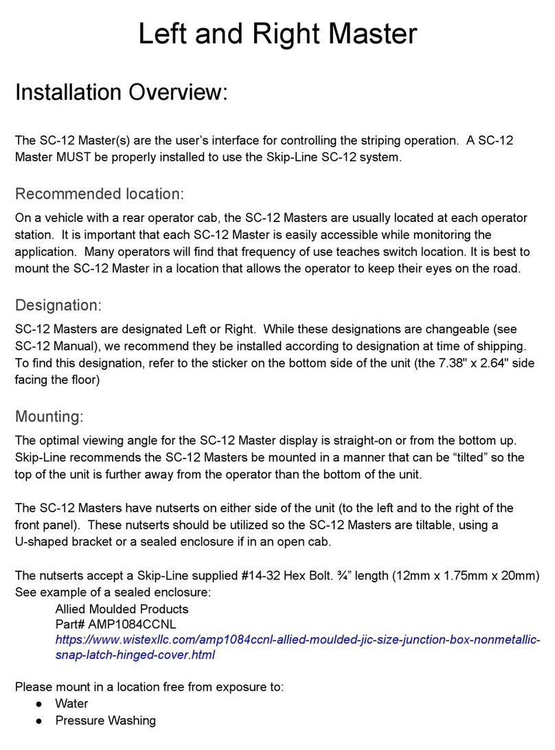
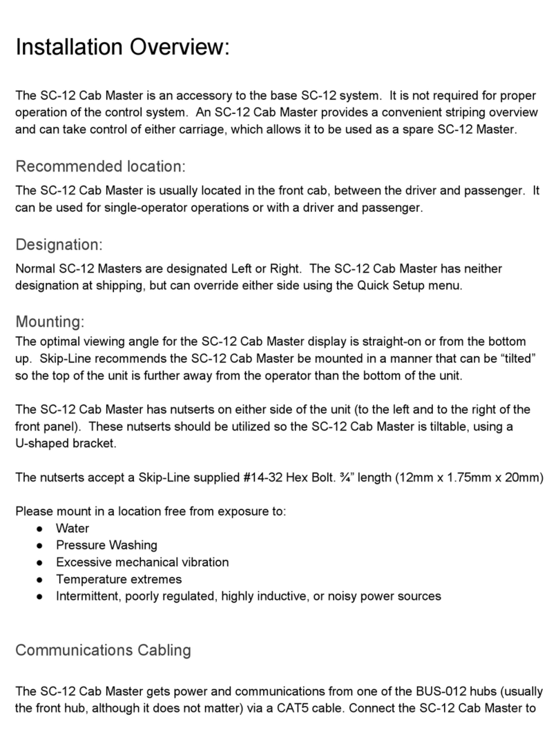
Skip-Line SC-12 User manual

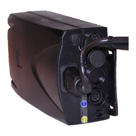
SC-12 Core Hub
Installation Overview:
The SC-12 Core Hub is a combination of a BUS-012 Hub and a SC-12 Core Skipper. It is a
BUS-012 Hub with a SC-12 Core Skipper embedded in it. The SC-12 Core Hub performs
several critical functions; 1) it supplies clean, filtered power to Skip-Line devices, and 2) it is the
communication hub for all Skip-Line products, 3.) it maintains the active skip cycles and holds
essential settings.
An SC-12 Core Hub or SC-12 Core Skipper MUST be properly installed to use the Skip-Line
SC-12 system.
Every vehicle requires at least two BUS-012 hubs (or a BUS-012 Hub and SC-12 Core Hub).
Skip-Line utilizes the proven and reliable CAN bus protocol, which requires two termination
points. The BUS-012 Hub and SC-12 Core Hub acts as those terminal points. Multiple Hubs
work together to create a communications network using CAT5 cables.
For more information on CAN Bus, here’s an interesting video: https://youtu.be/ZHaxv-cGZFI
Each Hub requires it’s own +12V and GROUND connections from a battery source.
Recommended location:
Front Hub (BUS-012):
The recommended location for the BUS-012 Hub labeled “Front Hub” is inside the front
cab of the vehicle. Mount in a location where CAT5 cables can be ran from dash-mounted
accessories. Common locations include inside the front console or on the back wall.
Rear Hub (SC-12 Core Hub):
The recommended location for the BUS-012 Hub labeled “Rear Hub” is inside the center
console or main rear cabinet of the vehicle. Mount in a location where CAT5 cables can be ran
from SC-12 Masters and output boxes.
Mid Hub(s) (BUS-012):
On advanced striping vehicles, mid-hubs are often used. They are not terminated like
Front and Rear Hubs. Place these where convenient (such as in a mid-deck enclosure)

Mounting:
The SC-12 Core Hub comes with two DIN clips on the device for top hat DIN rail mounting.
Skip-Line does not supply DIN rails, so please contact your preferred distributor or order DIN
rails online.
Use Top Hat DIN Rails:
EN 5022 35mm x 7.5mm
EN 5022 35mm x 15mm (deep version)
https://en.wikipedia.org/wiki/DIN_rail
https://www.digikey.com/product-detail/en/phoenix-contact/0807012/277-2064-ND/2179626
Note: Flange-mount SC-12 Core Hubs are available by request.
Please mount in a location free from exposure to:
● Water
● Pressure Washing
● Excessive mechanical vibration
● Temperature extremes
● Intermittent, poorly regulated, highly inductive, or noisy power sources
● Improper wiring
Linking Hubs (IMPORTANT!)
Connecting Two Hubs (Front BUS-012 and Rear SC-12 Core Hub):
Connect two Hubs using the UPLINK ports with a CAT5 cable. The CAT5 cable between two
hubs should be 20 meters or less in length. Never connect two hubs DOWNLINK to
DOWNLINK!!
Connecting Three or More Hubs:
If more than two hubs are on the vehicle, the recommended method for connecting them is from
an UPLINK port to a DOWNLINK port in a daisy-chain fashion. For example, use the UPLINK
port on a Rear Hub and a DOWNLINK port on a Mid Hub, then use the UPLINK port on the
same Mid Hub and a DOWNLINK port on a Front Hub. The CAT5 cable between two hubs
should be 20 meters or less in length.
Never connect two hubs DOWNLINK to DOWNLINK!!

Example of a Three-Hub Configuration:
Communications Cabling
The SC-12 Core Hub supplies clean, filtered power to Skip-Line devices via CAT5 cables.
Connect devices to the most convenient hub on any of the numbered hub jacks (1-8). It does
not matter which hub a device is connected to. Please keep CAT5 cables between the hub and
devices to a maximum length of 5 meters (16.4 ft).
If a device is properly connected to an SC-12 Core Hub or BUS-012 Hub, the large green port
light should be illuminated to indicate the device is pulling current. The CVO-312, DL-12, and
CPR-212 Paper Tape Printer all have separate power sources and will not cause the port light
to illuminate.
Cabling should use 26AWG (or larger) Cat5 cable and RJ45 connectors. Cat5 cable should not
be longer than 5 meters (16.4 feet). The Hubs accept only standard RJ45 plugs. Some of the
devices have sealed RJ45 jacks, available from Skip-Line, which will accept either standard or

strain-relieved IP-67 rated plugs. See Appendix B of the SC-12 Manual for instructions on RJ45
568-B connector wiring.
Avoid pinch points where the cable may be damaged from moving parts.
Tips:
● Use a continuity tester for all Cat5 cables
Power Connectors:
The SC-12 CoreHub requires +12V and GROUND from the vehicle (from primary battery or
auxiliary battery). Power and ground wires connect to the green 2-pin plug supplied by
Skip-Line. Leads are included with the 2-pin power plug for convenience. The red with is for
+12V, and the black wire is to GND. The plug positions are also labelled on the BUS-012 Box.
Recommended wire size for +12V and GND to the SC-12 Core Hub is 18-20 gauge wire.
Fusing:
Recommended fuse size for the SC-12 Core Hub is 10 amps.
Dimensions:
Smart Speedo: 7.38"W x 4.7"H x 2.21"D
Enclosure Used: Hammond 1590DBK
Connections:
The SC-12 Core Hub accepts a single 12-pin Euro Plug connector (supplied by Skip-Like). Pin
wiring may vary, so please refer to your vehicle’s wiring sheet for instructions.
Common Wiring Connections
Pin A: No connection. If upgrading from an SM-5 system, your A-L plug may have +12V on this
pin of the plug. It is acceptable to leave +12V connected here if you’re using the same
connector on an upgrade.

Pin B: No connection / GROUND. If upgrading from an SM-5 system, your A-L plug may have
GROUND on this pin of the plug. It is acceptable to leave GROUND connected here if you’re
using the same connector on an upgrade.
Pin C: Yellow Pump Stroke Sensor Input (NPN). This is an opto-isolated input from a pump
stroke sensor (limit switch, pressure switch, flow meter, etc). The SC-12 Core Hub is looking for
a grounding (NPN) signal from the sensor.
Pin D: White Pump Stroke Sensor Input (NPN). This is an opto-isolated input from a pump
stroke sensor (limit switch, pressure switch, flow meter, etc). The SC-12 Core Hub is looking for
a grounding (NPN) signal from the sensor.
Pin E: Ground Output for Sensors (NPN). The SC-12 Core Hub is providing GROUND for
sensors to use.
Pin F: Power Output (+5V) for Sensors. This is a clean, regulated +5V to use with unregulated
sensors. Note that this connection is rated to 350mA.
Pin G: Motion Sensor Input (NPN). This is an opto-isolated input from a motion sensor (5th
wheel encoder, hall effect sensor, etc). The SC-12 Core Hub is looking for a grounding (NPN)
signal from the sensor.
Pin H: Extra Opto-Isolated Input (NPN). Connection is for vehicles with more than two pump
stroke sensors. If less than or only two pump stroke sensors, this Pin has no connection. The
SC-12 Core Hub is looking for a grounding (NPN) signal from the sensor.
Pin I: Extra Opto-Isolated Input (NPN). Connection is for vehicles with more than two pump
stroke sensors. If less than or only two pump stroke sensors, this Pin has no connection. The
SC-12 Core Hub is looking for a grounding (NPN) signal from the sensor.
Pin J: No connection / GROUND.
Pin K: Extra Opto-Isolated Input (PNP). This connection is reserved for unique +12V (PNP)
signals.
Pin L: Transmission Reverse Input (PNP). This connection is looking for an active +12V (PNP)
signal from the vehicle to indicate the transmission is in reverse. This connection is optional,
but features such as Auto-Reverse Carriage Lift and CVO-312/DL-12 Backup Camera will not
function without a connection

Troubleshooting
Three-Color Port LED Indicators:
Indication:
Troubleshooting:
Off: No device connected
Check cabling.
GREEN: Device connected, drawing between
30mA and 700mA.
Normal! Flashing means this
port errored since last startup.
ORANGE: Device connected,
drawing between 700mA and 1A.
If device doesn't normally draw
this much, device may be faulty.
RED: Device overdrawing 1A limit.
Resettable fuse cutout imminent.
Check for breaks or pinches, and
for proper connector pinout.
Communications & Power Quality LED Indicators:
Label Meaning:
Troubleshooting:
TRAFFIC: Toggles every time traffic is
detected.
If not blinking, check that power and
comm cables are properly connected.
SLAVE: On when Core Skipper is detected.
If not blinking, check cabling between this

hub and the Core Skipper.
BUS ERR: On when a bus error has
occurred. Disappears once errors clears
Check cables and cable lengths.
Malfunctioning devices can also cause bus
error.
FAULT: Power fault detected. Power has
disappeared, or a power spike has occurred.
Check and tighten power connections.
Remove noisy devices from power branch.
SHORT: Total Hub current greater than 10A.
Check cabling to peripheral devices.
WARNING!!!
Always unplug all POWER, LOAD (green connectors) and CAT-5 cables
prior to any welding on the vehicle. Failure to do so may result in severe
damage to the unit.
Other manuals for SC-12
2
This manual suits for next models
1
Table of contents
Other Skip-Line Control System manuals
Popular Control System manuals by other brands
Varifan
Varifan MST-2B installation guide
Laguna Tools
Laguna Tools IQ HHC manual

Promation Engineering
Promation Engineering P2-12PN4-DC Installation & operation manual
Jandy
Jandy Aqualink RS OneTouch owner's manual
Gamma Vacuum
Gamma Vacuum DIGITEL MPCq instruction manual

Perrot
Perrot Greenkeeper Feedback user manual

zipwake
zipwake S Series troubleshooting guide
RadioMaster
RadioMaster TX16S user manual
West Mountain Radio
West Mountain Radio TARGETuner operating manual

Skov
Skov BlueControl 20RL Technical user guide
Hubbell
Hubbell Microprocessor Radio Locomotive Control... Brochure & specs
LOGICDATA
LOGICDATA LogicSP-2-1 user manual
