Skov BlueControl 20RL Manual

BlueControl
Extension box 20RL
Technical User Guide
604066 • 2023-02-23

BlueControl
2 Technical User Guide
Product and Documentation Changes
SKOV A/S reserves the right to change this document and the product herein described without further notice.
In case of doubt, please contact SKOV A/S.
The date of change appears from the front and back pages.
Note
• All rights belong to SKOV A/S. No part of this manual may be reproduced in any manner whatsoever without
the expressed written permission of SKOV A/S in each case.
• All reasonable efforts have been made to ensure the accuracy of the information contained in this manual.
Should any mistakes or imprecise information occur in spite of this, SKOV A/S would appreciate being noti-
fied thereof.
• Irrespective of the above, SKOV A/S shall not accept any liability with regard to loss or damage caused or
alleged to be caused by reliance on any information contained herein.
• Copyright by SKOV A/S.

BlueControl
1 Product description ....................................................................................................................................... 4
2 Product survey ............................................................................................................................................... 5
3 Mounting guide............................................................................................................................................... 6
3.1 Recommended tools.................................................................................................................. 6
3.2 Mounting the Extension Box .................................................................................................... 7
4 Installation guide............................................................................................................................................ 8
4.1 Installation of the Extension Box ............................................................................................. 8
5 Maintenance instructions ............................................................................................................................ 10
5.1 Cleaning.................................................................................................................................... 10
5.2 Recycling/Disposal .................................................................................................................. 10
6 Technical data .............................................................................................................................................. 11
6.1 Dimensioned sketch ................................................................................................................ 11
Technical User Guide

BlueControl
4 Technical User Guide
1 Product description
This User's Guide deals with the installation and connection of:
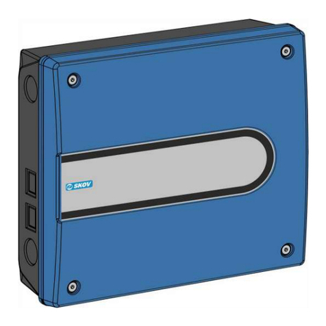
• 136471 BlueControl extension box 20RL with 2 x IO type 3, 10RL 8AI 8AO
The structure of the manual follows the required work routines. By following the instructions of the manual, you
will go through all steps in the correct order.
You can connect the BlueControl extension box to controllers from SKOV A/S.

BlueControl
Technical User Guide 5
2 Product survey
136471 BlueControl extension box 20RL
Extension box with 2 pcs. I/O module, 10RL 8AI 10RL, type 3.
0-10 V input or DOL 12 input or digital input (16)
0-10 V outputs (16)
Relays (20)
Used when more I/O modules are needed than are available in the standard
hardware.
The inputs can with a jumper be configured individually for either DOL 12,
DI (digital input) for water meters or AI (analog input, 0-10 V).
Includes rubber sleeves and ribbon cable
The controller's standard software/hardware supports 13 I/O modules in to-
tal. BlueControl extension box 20RL counts for 2 module

BlueControl
6 Technical User Guide
3 Mounting guide
3.1 Recommended tools
Below is a list of the tools recommended for the installation.
Topic Description
Crosshead screwdriver
Screwdriver straight slot (2 pcs.)
Power drill
Hammer

BlueControl
Technical User Guide 7
3.2 Mounting the Extension Box
Install the extension box so it is not exposed to frost or direct sunlight.
Mount the extension box to the left or the right of the controller.
Extension box left Controller
Extension box right
Controller
1. Knock out 2 knock-out pieces in the sides of the box (A) or (AA) and the side of the controller.
2. Knock out the required number of knock-out pieces (B) in the bottom section of the cabinet and mount the
plastic glands (C).
3. Prick/drill holes for the 4 screws in the bottom section of the cabinet (D).
4. Align the box horizontally. Hold the cabinet base against the wall and mark out the 4 screws.
5. Drill 4 x 8 mm holes.
6. Mount the cabinet using the enclosed wall dowels and screws.
7. Place one or more washer(s) under one of the cabinet feet if the wall is not level and the cabinet base
moves.
8. Mount the rubber sleeve (E).

BlueControl
8 Technical User Guide
4 Installation guide
Installation, servicing and troubleshooting of all electrical equipment must be carried out by quali-
fied personnel in compliance with the applicable national and international standard EN 60204-1
and any other EU standards that are applicable in Europe.
The installation of a power supply isolator is required for each motor and power supply to facilitate
voltage-free work on the electrical equipment. The power supply isolator is not included.
4.1 Installation of the Extension Box
Extension box with 2 x I/O modules (136471)
1. Connect the flat cable plug from I/O module 1 in the controller to I/O module 2 in the extension box (A)
2. Connect the flat cable plug from I/O module 2 to I/O module 3 in the extension box (B).
3. Set the jumper OFF/ON (C) on the controller I/O module 1 to OFF.
4. Set the jumper OFF/ON (D) on the extension box I/O module 2 to OFF.
5. Set the jumper OFF/ON (E) on the extension box I/O module 3 to ON.
Set the rotary switch of the I/O modules as follows:
I/O module 1
I/O module 2
I/O module 3
Address = 1
Address = 2
Address = 3
1. Connect the extension box earthing contact (F) to the earthing contact of the controller (G).
2. Route the ground cable through the lower rubber sleeve (H).
3. Set the CAN protocol jumper (I) as the main module. Set the CAN protocol jumper on the I/O module to
Classic if there is no jumper on the main module.
Extension Box Controller

BlueControl
Technical User Guide 9
Jumper setting
1. Adjust the jumpers (A) and (B)
Adjust the jumpers (A)
ON = Emergency opening can override relay so in-
let opens.
OFF = Factory setting. Emergency opening cannot
override relay.
Adjust the jumpers (B)
AI = Analog input.
DI = Digital input.
DOL 12 = DOL 12 input.
0 - 10 V inputs on the I/O module are set to:
Setting Application Placement
TEMP-INPUT
DOL 12 SENSOR
Temperature sensor input DOL 12 Topmost 2 pins
CONTACT-INPUT - Di
1k PULL-DOWN
E.g., water meter (digital input)
(pull down resistance = ON)
Lowermost 2 pins
ANALOG-INPUT - Ai
0 – 10V
E.g., humidity sensor (0-10V input)
(pull down resistance = OFF)
Lowermost 1 pin, or remove
the jumper.

BlueControl
10 Technical User Guide
5 Maintenance instructions
5.1 Cleaning
Clean the product with a cloth that has been wrung out almost dry in water and avoid using:
• high-pressure cleaner
• solvents
• corrosive/caustic agents
5.2 Recycling/Disposal
Products suitable for recycling are marked with a pictogram.
It must be possible for customers to deliver the products to local collection sites/recycling stations in accordance
with local instructions. The recycling station will then arrange for further transport to a certified plant for reuse,
recovery and recycling.

BlueControl
Technical User Guide 11
6 Technical data
Electrical
Rated voltage V AC 230/240 ± 10%
Operating voltage V AC 103.5-264
Frequency Hz 50/60
Max. power consumption A0.7
I/O module type 3
IO type 3, 10RL 8AI 8AO With jumpers for configuration of inputs.
Inputs 16 x 0-10 V DC input impedance 2.1 Mohm.
Pulsing Inputs
(E.g., water meter, energy
meter)
Minimum pulse length: 75 ms.
Minimum pulse interval: 75 ms.
Maximum frequency/pulse per sec.: 6 Hz.
Outputs/power supply 16 x 0-10 V DC output impedance 10 Ohm.
1 x motor supply 24V DC +/- 20% 0.4 A
Relays 20 x NO/NC potential free max.
Max. voltage/current at resistive load 250 V AC / 5 A AC.
Max. voltage/current at inductive load 250 V AC / 2 A AC CosPhi 0.8.
Mechanical
Cable knock-out punches 20 pcs. ø25.5 mm for M25 cable gland
2 ø40 mm in each side for the socket
Environment
Temperature, operation °C (°F) -10 to +45 (+14 to 113)
Storage temperature °C (°F) -25 to +60 (-13 to +140)
Ambient humidity, operation % RH 0-80
Protection class IP 54 (splashproof)
It is assumed that the base surface is level, i.e. ≤ 1.5 mm height differ-
ence, and the front panel screws are tightened to a minimum of 1.5
Nm.
Shipment
Dimension HxWxD mm 381x400x170
Dimensions when packed
HxWxD
mm 425x555x195
Shipping weight g 3500
6.1 Dimensioned sketch

604066 • 2023-02-23 • en-US • Made in Denmark
SKOV A/S • Hedelund 4 • Glyngøre • DK-7870 Roslev
Tel. +45 72 17 55 55 • www.skov.com • E-mail: [email protected]
This manual suits for next models
1
Table of contents
Other Skov Control System manuals

Skov
Skov Grow-Box Manual

Skov
Skov DOL 278 User manual

Skov
Skov BlueControl Pig User manual

Skov
Skov DOL 278T User manual

Skov
Skov DOL 278AMT-1 User manual

Skov
Skov DOL 34H Manual

Skov
Skov FarmOnline+ DataLink 131545 Manual

Skov
Skov DOL 532 Tunnel User manual
Skov
Skov DOL 635 User manual

Skov
Skov DOL 43X cULus User manual