Skope OD1100N User manual

OD1100N
Service Manual
MAN80336 Rev. 1.1 Sep. 2022
SKOPE Open Deck Fridge
Hydrocarbon

OD1100N
SKOPE Open Deck Fridge
Service Manual
MAN80336
Rev. 1.1 Sep. 2022
© 2022 SKOPE Industries Limited. All rights reserved.
SKOPE Industries Limited reserves the right to alter specifications without notice.
is a registered trademark of SKOPE Industries Limited.
SKOPE INDUSTRIES LIMITED
Head Office
PO Box 1091, Christchurch
New Zealand
A.B.N. 73 374 418 306
AU: 1800 121 535
NZ: 0800 947 5673
E-mail: [email protected]
Website: www.skope.com
Trademark Infringement
The SKOPE trademark on this product is infringed if the owner, for the time being, does any of the
following:
• Applies the trade mark to the product after its state, condition, get-up or packaging has been
altered in any manner
• Alters, removes (including part removal) or obliterates (including part obliteration) the trade
mark on the product
• Applies any other trade mark to the product
• Adds to the product any written material that is likely to damage the reputation of the trade
mark
Notice of the above contractual obligations passes to:
• Successors or assignees of the buyer
• Future owners of the product

SKOPE OD1100N
Service Manual iii
Contents
1 Specifications
SKOPE OD1100N. . . . . . . . . . . . . . . . . . . . . . . . . . . . . . . . . . . . . .5
2 Installation
Cabinet Location . . . . . . . . . . . . . . . . . . . . . . . . . . . . . . . . . . . . . . . . .6
Ventilation . . . . . . . . . . . . . . . . . . . . . . . . . . . . . . . . . . . . . . . . . . . .6
Power Cord . . . . . . . . . . . . . . . . . . . . . . . . . . . . . . . . . . . . . . . . . . .6
Transportation . . . . . . . . . . . . . . . . . . . . . . . . . . . . . . . . . . . . . . . . .6
Shelves . . . . . . . . . . . . . . . . . . . . . . . . . . . . . . . . . . . . . . . . . . . . . . . .6
Adjusting the Shelves . . . . . . . . . . . . . . . . . . . . . . . . . . . . . . . . . . .6
Gravity Shelf System. . . . . . . . . . . . . . . . . . . . . . . . . . . . . . . . . . . .8
3 Wiring
4 Electronic Controller
Overview . . . . . . . . . . . . . . . . . . . . . . . . . . . . . . . . . . . . . . . . . . . . . .10
Controller Faceplate . . . . . . . . . . . . . . . . . . . . . . . . . . . . . . . . . . . . .10
Buttons and Display . . . . . . . . . . . . . . . . . . . . . . . . . . . . . . . . . . .10
Service Mode . . . . . . . . . . . . . . . . . . . . . . . . . . . . . . . . . . . . . . . .11
SCS Connect Field App. . . . . . . . . . . . . . . . . . . . . . . . . . . . . . . . . . . 11
Connecting . . . . . . . . . . . . . . . . . . . . . . . . . . . . . . . . . . . . . . . . . .11
App Menu Items . . . . . . . . . . . . . . . . . . . . . . . . . . . . . . . . . . . . . .12
Faults and Alarms . . . . . . . . . . . . . . . . . . . . . . . . . . . . . . . . . . . . . . .13
5 Replacement Procedures
Overview . . . . . . . . . . . . . . . . . . . . . . . . . . . . . . . . . . . . . . . . . . . . . .18
Isolating Electrics . . . . . . . . . . . . . . . . . . . . . . . . . . . . . . . . . . . . . . .18
Security Grille (optional) . . . . . . . . . . . . . . . . . . . . . . . . . . . . . . . . . .18
Kick Panel . . . . . . . . . . . . . . . . . . . . . . . . . . . . . . . . . . . . . . . . . . . . .19
Sign . . . . . . . . . . . . . . . . . . . . . . . . . . . . . . . . . . . . . . . . . . . . . . . . . . 19
Fitting and Removing the Sign . . . . . . . . . . . . . . . . . . . . . . . . . . .20
Cladding . . . . . . . . . . . . . . . . . . . . . . . . . . . . . . . . . . . . . . . . . . . . . . 21
Removing and Refitting the Cladding . . . . . . . . . . . . . . . . . . . . . .21
Lighting . . . . . . . . . . . . . . . . . . . . . . . . . . . . . . . . . . . . . . . . . . . . . . .22
Shelf Lights . . . . . . . . . . . . . . . . . . . . . . . . . . . . . . . . . . . . . . . . . .22
Cabinet Electrics Gear Tray . . . . . . . . . . . . . . . . . . . . . . . . . . . . . . .23
Night Blind. . . . . . . . . . . . . . . . . . . . . . . . . . . . . . . . . . . . . . . . . . . . . 24
Night Blind Sensor Switch. . . . . . . . . . . . . . . . . . . . . . . . . . . . . . .24
Refrigeration System. . . . . . . . . . . . . . . . . . . . . . . . . . . . . . . . . . . . . 25
Before Servicing . . . . . . . . . . . . . . . . . . . . . . . . . . . . . . . . . . . . . .25
On-site Work . . . . . . . . . . . . . . . . . . . . . . . . . . . . . . . . . . . . . . . . . 26
Off-site Work . . . . . . . . . . . . . . . . . . . . . . . . . . . . . . . . . . . . . . . . . 26
Diagnosing Lack of Gas . . . . . . . . . . . . . . . . . . . . . . . . . . . . . . . .27
Refrigeration Cartridge . . . . . . . . . . . . . . . . . . . . . . . . . . . . . . . . . . . 27
Cartridge Removal . . . . . . . . . . . . . . . . . . . . . . . . . . . . . . . . . . . . 28
Cartridge Electrics Box . . . . . . . . . . . . . . . . . . . . . . . . . . . . . . . . .29
Condenser Fan . . . . . . . . . . . . . . . . . . . . . . . . . . . . . . . . . . . . . . .31
Evaporator Fan . . . . . . . . . . . . . . . . . . . . . . . . . . . . . . . . . . . . . . .32
Compressor. . . . . . . . . . . . . . . . . . . . . . . . . . . . . . . . . . . . . . . . . .34
Electronic Controller . . . . . . . . . . . . . . . . . . . . . . . . . . . . . . . . . . . . .35
Electronic Controller Location . . . . . . . . . . . . . . . . . . . . . . . . . . . . 35
Replacing the Controller . . . . . . . . . . . . . . . . . . . . . . . . . . . . . . . .35
PIR Sensor . . . . . . . . . . . . . . . . . . . . . . . . . . . . . . . . . . . . . . . . . .36
Control and Evaporator Probes. . . . . . . . . . . . . . . . . . . . . . . . . . .37
Condenser Probe . . . . . . . . . . . . . . . . . . . . . . . . . . . . . . . . . . . . .38

SKOPE OD1100N
Service Manual
iv
6 Spare Parts
Ordering . . . . . . . . . . . . . . . . . . . . . . . . . . . . . . . . . . . . . . . . . . . . 40
Cabinet . . . . . . . . . . . . . . . . . . . . . . . . . . . . . . . . . . . . . . . . . . . . . . . 40
Refrigeration Cartridge . . . . . . . . . . . . . . . . . . . . . . . . . . . . . . . . . . . 42
Cartridge Electrics Box . . . . . . . . . . . . . . . . . . . . . . . . . . . . . . . . . . . 44
Sign. . . . . . . . . . . . . . . . . . . . . . . . . . . . . . . . . . . . . . . . . . . . . . . . . . 45
High Sign . . . . . . . . . . . . . . . . . . . . . . . . . . . . . . . . . . . . . . . . . . . 45
Low Sign. . . . . . . . . . . . . . . . . . . . . . . . . . . . . . . . . . . . . . . . . . . . 46
7 Maintenance
Cleaning . . . . . . . . . . . . . . . . . . . . . . . . . . . . . . . . . . . . . . . . . . . . . . 47
Cabinet . . . . . . . . . . . . . . . . . . . . . . . . . . . . . . . . . . . . . . . . . . . . . 47
Condenser Filter and Coil. . . . . . . . . . . . . . . . . . . . . . . . . . . . . . . 47
8 Troubleshooting
Electronic Controller . . . . . . . . . . . . . . . . . . . . . . . . . . . . . . . . . . . . . 48
Cabinet and Refrigeration Cartridge. . . . . . . . . . . . . . . . . . . . . . . . . 48
5
SKOPE OD1100N
Specifications
Service Manual
1 Specifications
OD1100N See also the relevant specification sheets on the SKOPE website (www.skope.com):
PSS1040 – Open Deck Fridge with High Sign
PSS1041 – Open Deck Fridge with Low Sign
Cabinet
Refrigeration Cartridge
Description Free-standing Open Deck Fridge
SKOPE ID O11CLN
Dimensions External Internal
Height (mm) 2204 (high sign) 2019 (low sign) 1432
Width (mm) 1272 1191
Depth (mm) 836 (includes 50 mm spacer) 628
Floor area (m2)1.06 (includes 50 mm spacer)
Capacity (L) 1071
Shelves
4 adjustable angle (8° or flat), adjustable height shelves +
1 adjustable angle (8° or flat) bottom shelf. Optional gravity feed
system available.
Top two shelves: 1170W × 360D, middle two shelves: 1170W ×
380D, bottom shelf: 1179W × 400D
Operating conditions
Maximum ambient temperature 25°C @ 60% relative humidity (Climatic Class 3)
Product temp. range -1°C to +5°C
Electrical 220-240 volts a.c. 50 Hz, single phase supply
Current draw (A) 5.8
Sign lighting 1 × 7.5 W sign light
Internal lighting 5 × 7.5 W LED shelf lights
Description R290 (hydrocarbon) Open Deck Cartridge
Cartridge model UBQENI-0052
Compressor Embraco NT6230U
Controller SCS Connect
Nominal capacity (W) 2100
Refrigerant R290/150 g

6Installation
Service Manual
SKOPE OD1100N
2 Installation
The fridge is designed to operate within a climate class 3 environment (25°C @ 60% relative
humidity), and should not be placed in a location that is likely to exceed these conditions.
Cabinet
Location Do not expose the cabinet to direct sunlight at any time, as this may cause plastic parts to
distort.
Do not place the cabinet in the direct airpath of air-conditioning outlets, ventilation fans or any
other fan which causes air movement directly into the cabinet opening. This will cause failure
of the air curtain and compromise the airflow and product temperature in the open cabinet
zone. Maximum air movement across the cabinet opening must not exceed 0.2 m/s.
Ventilation To prevent overheating and conserve energy, ensure there is always at least a 50 mm gap at
the back, 200 mm on the top and 60 mm at the sides of the cabinet. Keep the ventilation slots
in the lower front panel clear at all times. Never store cardboard cartons or other objects in front
of the fridge.
To maximise airflow at the rear of the cabinet, ensure both rear stand-offs are fully extended
outwards and locked into place. This will provide the necessary air gap at the rear of the
cabinet for correct operation.
Power Cord The fridge has a flexible power cord fitted with a 3-pin plug, at the rear of the cabinet. Take care
not to trap the cord or plug when positioning the cabinet.
Transportation The cabinet is not designed to be stable while in motion. Use extreme caution when moving
or transporting the cabinet if it has been removed from its original crate.
Never strap across the glass sides of the cabinet as this may cause damage.
Ensure appropriate padding or protection is used to prevent damage when strapping.
Shelves
Adjusting the
Shelves The fridge is fitted with five metal shelves. The four top shelves are height and angle
adjustable, and removable. The angled bottom shelf is angle adjustable. The top two shelves
are 1170W × 360D, the middle two shelves are 1170W × 380D, and the bottom shelf is
1179W × 400D.
IMPORTANT
The cabinet’s recommended operating temperature is between
18°C and 24°C and 60% relative humidity.
IMPORTANT
Do not leave the cabinet exposed to direct sunlight as this may
cause distortion of plastic parts.
IMPORTANT
There must be no air movement directly into the cabinet opening.
CAUTION
To prevent over-heating and conserve energy, ensure that air can
flow freely all around the cabinet, including underneath and on
top.
7
SKOPE OD1100N
Installation
Service Manual
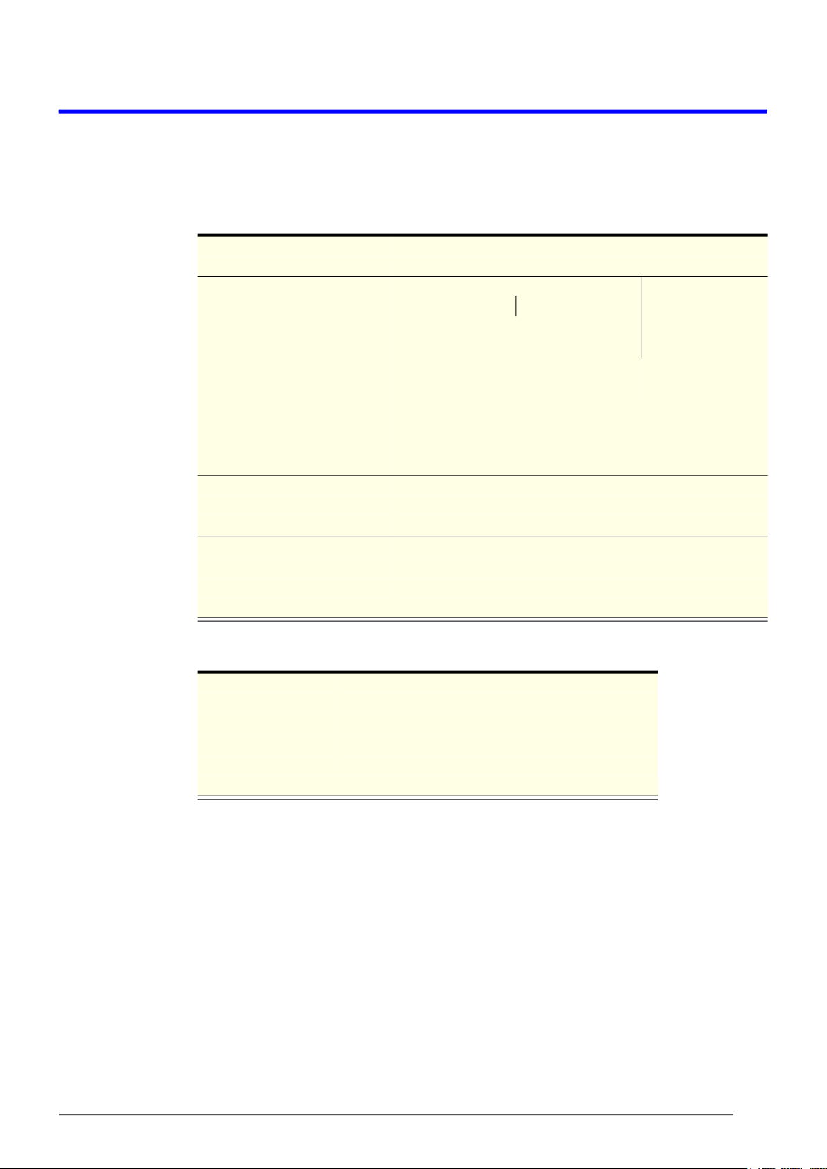
The four top shelves are held in place by two cantilevered shelf brackets which clip into cut-
outs in the cabinet back duct. The top four shelves can be adjusted at 28 mm increments (see
image below).
Procedure 1: To reposition a shelf
1. Disconnect the cabinet from the power supply (see page 18).
2. Remove product from the shelf that is being moved.
3. If present, lift the gravity feed matting from the shelf and remove from the cabinet.
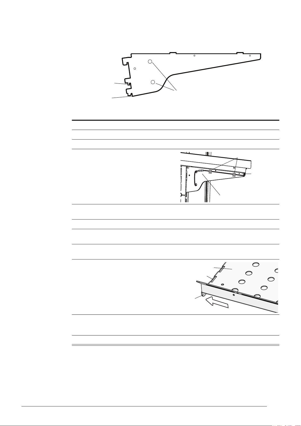
4. Unplug the shelf light cable at the inside of the
right hand shelf bracket.
5. Lift the shelf up off the brackets and remove from the cabinet. Be careful not to damage the shelf
light cable.
6. Unwind the cable from the back of the shelf bracket.
7. Select the new position and move the shelf brackets. The shelves can be repositioned as far as
the shelf light cable reasonably allows.
8. Place the shelf, and if present the gravity feed matting, onto the shelf brackets. Ensure the back
of the shelf clips over the rear of the brackets.
9. Push the cantilevered brackets outwards until
they clip into the edge locating slots on the
side of the shelf.
10. Take up any excess shelf light cable by winding it through the two holes at the rear of the shelf
bracket, and reconnect the shelf light cable plug. Make sure that the plug is securely attached to
the correct socket.
11. Reconnect the cabinet to the power supply, and check for correct operation.
Position for
level shelves
Position for
angled shelves
Excess shelf light
cable holes
Shelf light cable plug
Shelf bracket
Adhesive cable clips
Locating slot
Shelf
Shelf
bracket

8Installation
Service Manual
SKOPE OD1100N
Gravity Shelf
System Gravity feed matting, including shelf dividers, is available for each shelf. The gravity shelf
system comes in two sizes to suit the different size shelves: 350 mm depth for the top four
shelves, and 385 mm for the bottom shelf. Each has 16 dividers.
Procedure 2: To fit the gravity feed matting and shelf dividers
1. Match up the shelf dividers with the corresponding matting.
2. Work across the matting and fit the centre dividers at required intervals.
3. Place the mat and dividers onto the matching shelf inside the cabinet.
4. Repeat for the remaining shelves.
5. To adjust the spacing between dividers:
•Push the divider towards the rear of the cabinet until it unclips from the matting.
•Move the divider to the required spacing, and insert into the slot in the matting kit.
•Pull the matting towards the front of the cabinet to lock it in place.

9
SKOPE OD1100N
Wiring
Service Manual
3 Wiring
GNYE
GNYE
WDTL SC S
Controller
L N
C
R
R
DI1
0V AD1
DI2
0V AD2
DI3
0V AD3
DI4
5V
0V
AD4
DI5
0V
LED1
LED2
LED3
AD5
SSR
S1
S2
SSR
Comp.
BN
BU
T1-1
T1-2
S3-4 P3-4
S5-2 P5-2 P4-1 S4-1
S4-4 P5-4
S4-2 P4-2
P5-1 S5-1
BK
S4-4 P4-4
BK
BU
BN BN BU
BK
BK
BK
BN
S3-2 P3-2
BN BN
BU
BU
BN
S6-4 P6-4
S8-2 P8-2 P7-1 S7-1
S8-4 P8-4
S7-2 P7-2
P8-1 S8-1
BK
S7-4 P7-4
BK
BU
BN BN BU
BK
BK
BK
BN
S6-2 P6-2
BN BN
BU
BU
BN
Compressor
S2-2 P2-2
BK
BN
S2-1 P2-1
BU
BU
BU
LED P ower
Supply
N
L
+
-
P9-1 S9-1
BU
S9-1 P9-1
BN BN
BU
RD
P12 S12
WH
BK
P11 S11
WH
BK
P14 S14
BK
Control
Sensor
Evaporator
Sensor
Cabinet
Lighting
WH
BK
P13 S13
WH
BK
Condenser
Sensor
Element
GN
BU
RD
BK
BU
BU
BK
BK
RD RD
BK
WH
RD
RD
RD
RD
RD
RD
RD
BK
BU
BU
BU
BN
GY
BN
BU
WH
WH/BK
WH
WH/BK
WH
WH/BK
WH
WH/BK
Curtain Switch
BK
PIR Sensor
(Reach-in), plus
program port
(Blue 4-way)
BK
S10-1 P10-1
S10-2 P10-2
S15-5 P15-5
S15-1 P15-1
S15-2 P15-2
S15-3 P15-3
S15-4 P15-4
P16-1 S16-1
P16-2 S16-2
P17 S17
P17 S17
P17 S17
P17 S17
S1-L P1-L
P1-N S1-N
WH
WH/BK
P17 S17
WH
WH/BK
P18 S18
RD
RD
BN
BN
BN
EMC Filter
BN
BU
BU
BN
L E
N
BN
BU
P3-1 S3-1
P6-1 S6-1
BU
BU
BU
Sign Light
P19 S19
RD
WH
Evapor ator
Fan Motors
Condenser
Fan Motors
GNYE
GNYE
WDTL SC S
Controller
L N
C
R
R
DI1
0V AD1
DI2
0V AD2
DI3
0V AD3
DI4
5V
0V
AD4
DI5
0V
LED1
LED2
LED3
AD5
SSR
S1
S2
SSR
Comp.
BN
BU
T1-1
T1-2
S3-4 P3-4
S5-2 P5-2 P4-1 S4-1
S4-4 P5-4
S4-2 P4-2
P5-1 S5-1
BK
S4-4 P4-4
BK
BU
BN BN BU
BK
BK
BK
BN
S3-2 P3-2
BN BN
BU
BU
BN
S6-4 P6-4
S8-2 P8-2 P7-1 S7-1
S8-4 P8-4
S7-2 P7-2
P8-1 S8-1
BK
S7-4 P7-4
BK
BU
BN BN BU
BK
BK
BK
BN
S6-2 P6-2
BN BN
BU
BU
BN
Compressor
S2-2 P2-2
BK
BN
S2-1 P2-1
BU
BU
BU
LED P ower
Supply
N
L
+
-
P9-1 S9-1
BU
S9-1 P9-1
BN BN
BU
RD
P12 S12
WH
BK
P11 S11
WH
BK
P14 S14
BK
Control
Sensor
Evaporator
Sensor
Cabinet
Lighting
WH
BK
P13 S13
WH
BK
Condenser
Sensor
Element
GN
BU
RD
BK
BU
BU
BK
BK
RD RD
BK
WH
RD
RD
RD
RD
RD
RD
RD
BK
BU
BU
BU
BN
GY
BN
BU
WH
WH/BK
WH
WH/BK
WH
WH/BK
WH
WH/BK
Curtain Switch
BK
PIR Sensor
(Reach-in), plus
program port
(Blue 4-way)
BK
S10-1 P10-1
S10-2 P10-2
S15-5 P15-5
S15-1 P15-1
S15-2 P15-2
S15-3 P15-3
S15-4 P15-4
P16-1 S16-1
P16-2 S16-2
P17 S17
P17 S17
P17 S17
P17 S17
S1-L P1-L
P1-N S1-N
WH
WH/BK
P17 S17
WH
WH/BK
P18 S18
RD
RD
BN
BN
BN
EMC Filter
BN
BU
BU
BN
L E
N
BN
BU
P3-1 S3-1
P6-1 S6-1
BU
BU
BU
Sign Light
P19 S19
RD
WH
Evapor ator
Fan Motors
Condenser
Fan Motors
WIRE COLOURS
BK Black
BN Brown
RD Red
OG Orange
GN Green
BU Blue
GY Grey
WH White
GNYE Green-Yellow
Based upon IEC 757 Standard
LEGEND
T1 Unit junction box terminals S11/P11 Control sensor socket/plug (blue 2-way)
S1/P1 IEC isolation socket/plug S12/P12 Evaporator sensor socket/plug (black 2-way)
S2/P2 Compressor socket/plug (blue 4-way) S13/P13 Condenser sensor socket/plug (red 2-way)
S3/P3 Condenser fan motor socket/plug (red 4-way) S14/P14 Door curtain switch socket/plug (white 2-way)
S4/P4 Fan motor socket/plug (red 4-way) S15/P15 Cabinet supply socket/plug (white 6-way)
S5/P5 Fan motor socket/plug (red 4-way) S16/P16 Heater socket/plug (black 3-way)
S6/P6 Evaporator fan motor socket/plug (white 4-way) S17/P17 Cabinet light sockets/plugs (red 2-way)
S7/P7 Fan motor socket/plug (red 4-way) S18/P18 Sign light socket/plug (white 3-way)
S8/P8 Fan motor socket/plug (red 4-way) S19/P19 Sign light top socket/plug (red 2-way)
S9/P9 LED driver input plug (on cartridge) (white 3-way) O Terminal block terminal
S10/P10 LED driver output socket/plug (red 2-way) >> Plug and socket

10 Electronic Controller
Service Manual
SKOPE OD1100N
4 Electronic Controller
Overview
The fridge is fitted with an SCS Connect electronic controller. The controller is located behind
the kick panel, in the electrics junction box, which is at the front of the refrigeration cartridge.
The controller is pre-programmed. SKOPE does not recommend changing the settings unless
it is absolutely necessary. To ensure efficient operation, the controller automatically forces a
defrost cycle when required.
Controller Faceplate
Buttons and
Display The faceplate includes the front display panel and interface buttons.
IMPORTANT
The controller must only be adjusted by an authorised service agent.
Table 1: Controller Faceplate
No. Description Use
1 Night Mode Indicator On during night mode.
2 Display Indicator
Digital display of:
• the cabinet’s air (not product)
temperature.
• alarm messages.
3Light Switch - Night Mode
(back/abort) Button Used during programming.
Press to switch the lights on or off.
Press and hold to switch the fridge
between Day and Night modes.
4 Up Button Used during programming.
5 Bluetooth Indicator On when ready to connect to a device.
Flashing when connected to a device.
6 Defrost Cycle (next/enter) Button Used during programming. Press and hold to start a manual
defrost.
7 Down Button Used during programming.
8 Fault - Alarm Indicator On during a fault or alarm.
9 Compressor Indicator On when the compressor is running.
10 Defrost Mode Indicator On during the defrost cycle.
11 Fan Indicator On when the fans are running.
12 3 4 5
8 7
11
10
96
11
SKOPE OD1100N
Electronic Controller
Service Manual
Service Mode The service mode can be run using the controller faceplate, but SKOPE strongly recommends
using the SCS Connect Field app. You will need a 9-digit PIN to enter the service mode via the
controller. If you don’t have one, contact Customer Services to request a PIN.
Service mode includes:
Parameters
Allows you to access and edit individual controller parameters.
Reset
Returns the controller back to factory or default settings.
Manual test
Allows you to see the input values from the sensors, check the effects of output adjustments
to peripherals, and run preset test routines.
Statistics
Displays logged values and event counts for diagnostics and fine tuning.
About
Lists the properties of the refrigeration system and the controller, including fridge model codes,
and firmware, hardware and software versions.
Refer to Wellington Drive Technologies documentation for further information.
SCS Connect Field App
Connecting The SCS Connect Field app gives authorised service technicians wireless access to the
controller from mobile devices with Bluetooth capability. The app provides data logging, alarm
notification, and control over inputs (probes, switches) and outputs (e.g. relays).
Procedure 3: To install the SCS Connect Field app
Before you start
When you first run the app, you will need to enter an activation code – a 9-digit PIN. If you don’t
already have one, contact Customer Services to request an activation code. You will need to be
connected to the internet at the time of activation.
Your activation code is unique to you, and determines your personal level of access for the app. Never
share it with anyone else. The same code will give you access to all SCS apps you are authorised to
use.
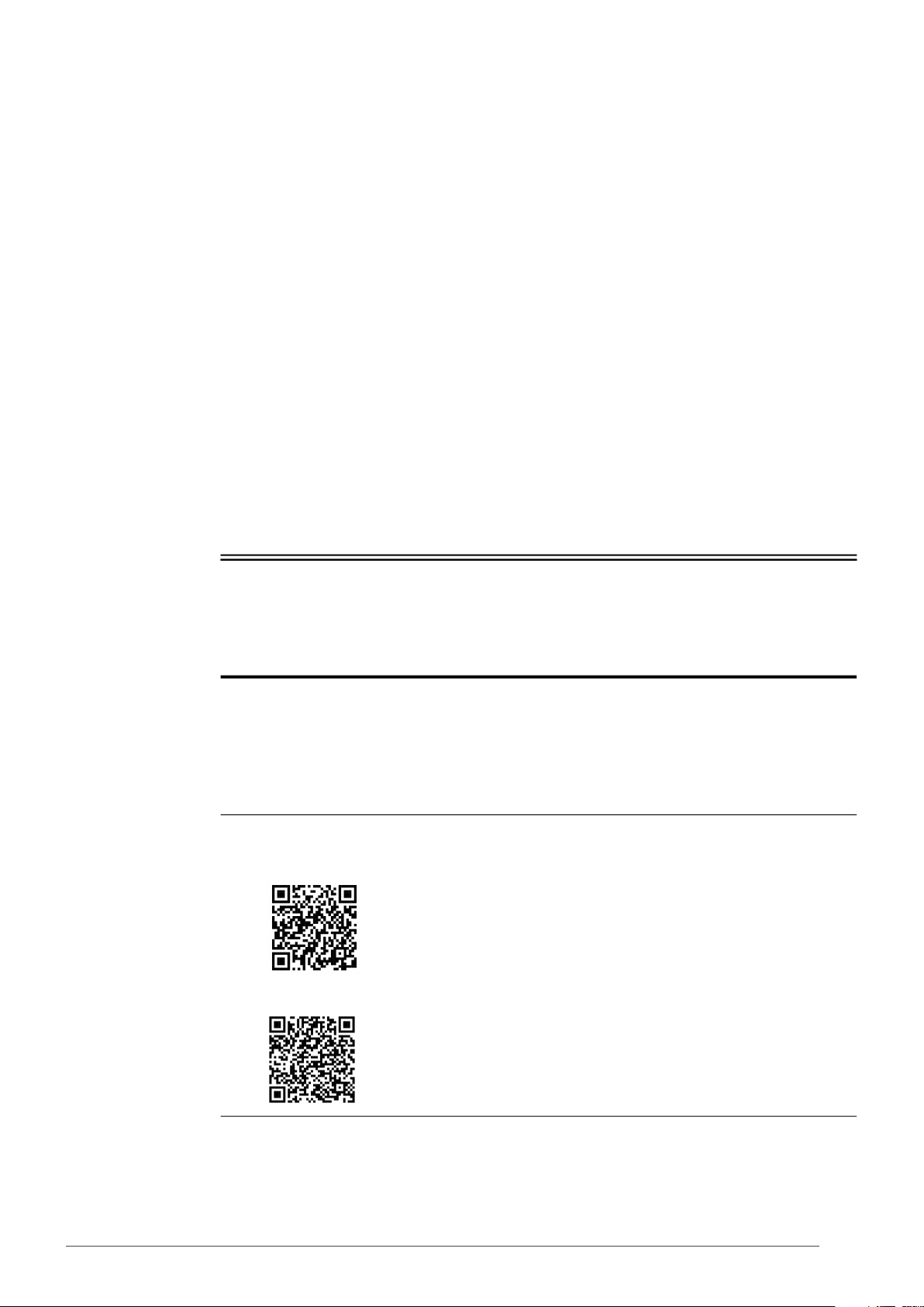
1. Download and install the Connect Field app
•Apple App Store:
https://apps.apple.com/nz/app/scs-connect-field/id1172570106
•Google Play Store:
https://play.google.com/store/apps/details?id=air.com.wdtl.scs.diagnostic.mobile

12 Electronic Controller
Service Manual
SKOPE OD1100N
App Menu
Items You can find information and make changes to the connected controller and its fridge via the
app menu.
Home screen
Shows a graphic representation of the fridge being controlled.
2. Make sure you are connected to the internet, and enter your 9-digit activation code.
3. Once activation is complete, you must define a 4-digit PIN. This can be any code unique to you.
Each time you start the app, you will be required to enter this same PIN. This is to prevent other
people accessing the app from an unlocked phone.
Procedure 4: To connect to a controller
1. Check that the Bluetooth logo on the top right of the controller faceplate is unlit, indicating that the
controller is ready to connect to a device.
Note: A flashing Bluetooth logo indicates that the controller is currently connected to a device.
2. Open the SCS Connect Field app.
3. Select the controller from the list of visible controllers.
Note: This list is filtered by your activation permissions, so devices you are not authorised to
connect to will not be displayed.
4. Select “CONNECT” to connect to the controller.
5. Check that the Bluetooth logo on the top right of the controller faceplate is flashing, indicating that
the controller is connected.
Procedure 3: To install the SCS Connect Field app (continued)
Table 2: SCS Connect Field App Home Screen
Item Description Action
Output control Gives you control of the input sensors and switches,
and output relays.
Edit parameters
Allows you to access and edit individual controller
parameters.
SKOPE does not recommended changing
parameters unless absolutely necessary.
If you edit a parameter, you must:
• select “DISCONNECT” from the menu to apply
the updated parameter.
• record the changes on the warranty/job card.

13
SKOPE OD1100N
Electronic Controller
Service Manual
Faults and Alarms
If a fault occurs, it is logged, the Fault - Alarm indicator is lit on the controller faceplate, and a
message may be displayed. Faults do not affect product temperature, and do not require
action from the shop owner, unless they turn into an alarm.
If an alarm occurs, it is logged, the Fault - Alarm indicator is lit, and the alarm message is
displayed on the controller faceplate. Alarms may result in abnormal product temperature.
Some faults and alarms can be cleared by the shop owner, and others can only be cleared by
a service technician. Faults and alarms can be cleared by the shop owner by power-cycling
the cabinet. However the fault or alarm will only clear if the problem has been fixed. If the
problem still exists after a power-cycle, a service technician will need to fix the problem.
Load parameter file
Allows you to reload a default parameter set or
change to new parameter set.
SKOPE does not recommended changing
parameters unless absolutely necessary.
1. If you suspect an incorrect parameter setting,
reload the complete parameter set.
2. After loading the new parameter set, select
“DISCONNECT” from the menu to apply the
updated parameters.
Statistics
Displays information from the past seven days about
the fridge's activity, including temperatures and
alarms.
SCS info Displays information about the cabinet and the
controller version.
SCS setup Allows you to add or change SCS info (see above).
Disconnect Allows you to disconnect from the currently
connected controller.
Settings
Allows you to change the app's general settings and
see which databases you have activated. You can
have more than one database activated at the same
time.
To add a new database, select ACTIVATE
ANOTHER DATABASE, and enter the new
database's unique activation code.
Table 2: SCS Connect Field App Home Screen (continued)
Item Description Action
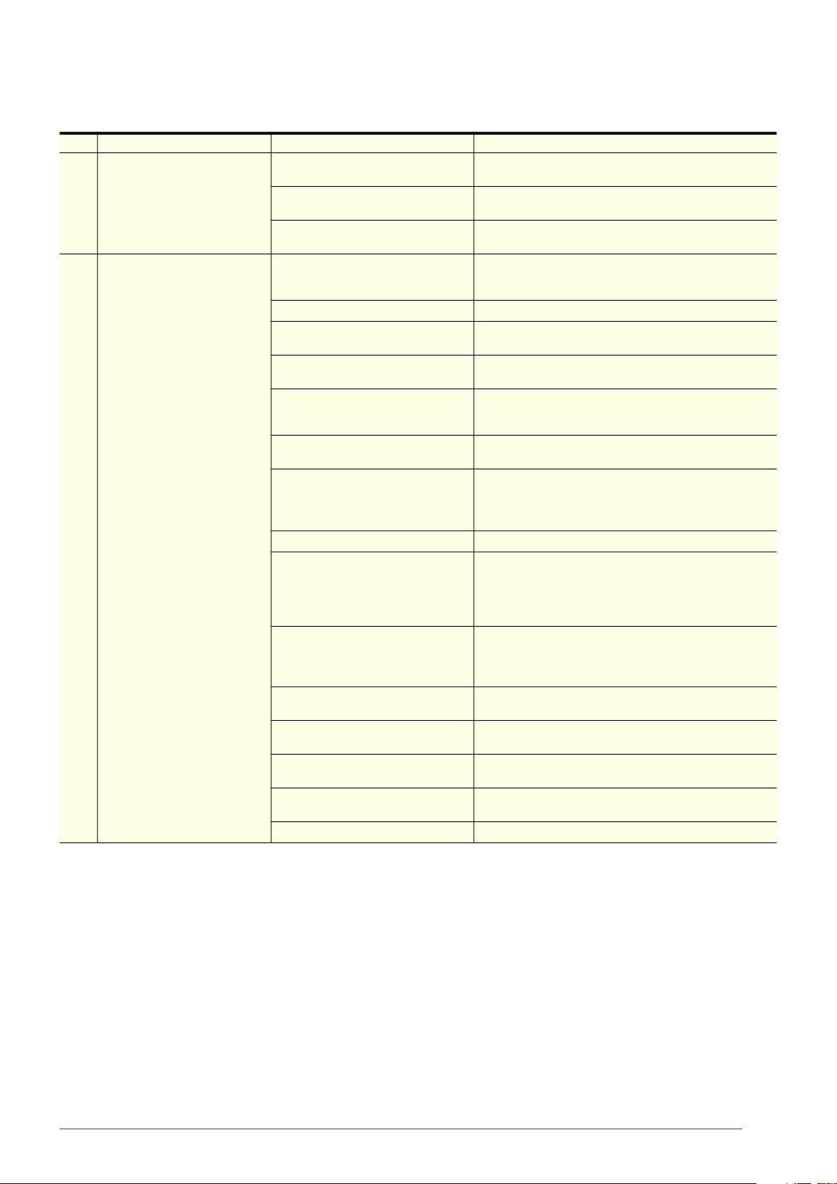
Table 3: Faults
Description Possible root cause Actions
Over-voltage protection
The maximum allowable mains supply
voltage has been exceeded. The
cabinet has temporarily shut down to
prevent damage and will restart once
the supply voltage decreases.
Should be a one-off. If it continues,
consider:
• poor line voltage
Test the incoming voltage to ensure it is correct. The
test voltage needs to be between 198 and 264 volts.
• If outside this, the controller will shut the system
down until the voltage returns to between these
measurements.
• If the voltage is correct and the controller is still
showing a fault, replace the controller.
• rural location
• voltage setting parameter
• Check the voltage parameter settings are
between 198 and 264 volts. If this parameter is
outside the correct voltage, changing it may
damage the controller.
• controller • The controller may be reading incorrectly and
need replacing.

14 Electronic Controller
Service Manual
SKOPE OD1100N
Under-voltage protection
The mains supply voltage has dropped
below the minimum allowable level.
The cabinet has temporarily shut down
to prevent damage and will restart
once the supply voltage increases.
Should be a one-off. If continues,
consider:
• power supply overloaded Test the incoming voltage to ensure it is correct. The
test voltage needs to be between 198 and 264 volts.
• If outside this, the controller will shut the system
down until the voltage returns to between these
measurements.
• If the voltage is correct and the controller is still
showing a fault, replace the controller.
• poor line voltage
• multi-box use
• Check that there are not too many plugs using the
same multi-box adaptor causing the voltage to
drop.
• rural location
• voltage setting parameter
• Check the voltage parameter settings are
between 198 and 264 volts. If this parameter is
outside the correct voltage, changing it may
damage the controller.
• controller • The controller may be reading incorrectly and
need replacing.
High condensing temperature
protection
The system was operating at an
elevated temperature and has
temporarily shut down to prevent
damage. Extended operation in this
condition may result in ALARM 15,
increased energy consumption and a
reduction in cabinet life.
Cartridge swap is not required.
• Condenser not clean
• Remove and clean the condenser filter.
• Check that the condenser is free of debris.
• If the coil is dirty, clean it with a vacuum cleaner or
soft brush.
• Poor installation or ventilation • Check the installation guidelines.
• If fitted, check the rear stand-offs are extended.
• Condenser fan motor or blade • Check that the condenser fan blades are in place
and all condenser fans are operating correctly.
• Controller
The controller may be reading incorrectly and need
replacing.
• Confirm the temperature reading with an
independent thermometer.
• Very high ambient temperature • Check if the probes are faulty and reading
incorrectly.
Excessive compressor cycling
protection
The system has been turning on and
off too frequently.
• Blocked condenser
• Remove and clean the condenser filter.
• Check that the condenser is free of debris.
• If the coil is dirty, clean it with a vacuum cleaner or
soft brush.
• Poor installation or ventilation • Check the installation guidelines.
• Cartridge gasket seals leaking • Remove the cartridge and check the integrity of
the gaskets and seals.
• Hot product • Check if the product has been recently loaded,
and is causing the extra heat.
• Product blocking cabinet airflow
• Check if the return air grille is covered by product.
If so, move the product from the grille and
observe.
• Compressor is overloaded from
ambient temperature
• Ensure that the cabinet is operating in its climate
class.
• Condenser or evaporator fan
motor or blade
• Inspect the condenser and evaporator fans safely,
and replace if faulty.
• Controller • The controller may be reading incorrectly and
need replacing.
• Compressor or gas leak • Swap the cartridge.
Table 3: Faults (continued)
Description Possible root cause Actions
15
SKOPE OD1100N
Electronic Controller
Service Manual
Table 4: Alarms
Code Description Possible root cause Action
8
Estimated product
temperature below allowable
range
The estimated product
temperature has been below
the allowable range for longer
than the permissible time.
• Low ambient temperature • Ensure that the cabinet is operating in its climate
class.
• App settings • Check all app settings, and reinstall the
parameters if required.
• Controller • Check the probe calibration to make sure that the
controller is reading the temperature correctly.
• Disrupted air curtain
• Check that the fridge is not near an air
conditioning grille which is blowing onto it,
causing airflow problems.
9
Estimated product
temperature above allowable
range
The estimated product
temperature has been above
the allowable range for longer
than the permissible time.
• Sealed refrigeration system • Consider a cartridge swap.
• Incorrect setpoint • Reload the correct parameters using the SCS
Connect Field app.
• Too much product • If the cabinet is overloaded, remove the excess
product.
• Blocked return air grille
• Check if the return air grille is covered by product.
If so, move the product from the grille and
observe.
• Warm product loaded into
cabinet
• Blocked condenser
• Remove and clean the condenser filter.
• Check that the condenser is free of debris.
• If the coil is dirty, clean it with a vacuum cleaner or
soft brush.
• Poor installation or ventilation • Check the installation guidelines.
• Frozen or blocked evaporator
coil
• De-ice the coil and check the that evaporator fan
motor is working.
• Check the defrost cycle and that the defrost probe
are working correctly.
• Check that the drain is clear.
• Cartridge gasket leaking (to
cabinet seal or lid seal)
• Check that the gasket is intact and not broken
and leaking.
• Ensure the installation levers are lifting the
cartridge up onto the case correctly.
• Compressor is overloaded from
ambient temperature
• Ensure that the cabinet is operating in its climate
class.
• Condenser or evaporator fan
motor or blade
• Inspect the condenser and evaporator fans safely,
and replace if faulty.
• Incorrect parameter settings • Use the SCS Field app to check that the correct
setpoint and parameters have been selected.
• Controller • Check the probe calibration to make sure that the
controller is reading the temperature correctly.
• Compressor or gas leak • Swap the cartridge.
16 Electronic Controller
Service Manual
SKOPE OD1100N
15
Excessive condensing
temperature protection
The system was operating at an
excessive temperature and has
shut down to prevent
permanent damage.
Cartridge swap is not required.
• Very high ambient temperature • Ensure that the cabinet is operating in its climate
class.
• Condenser is not clean
• Remove and clean the condenser filter.
• Check that the condenser is free of debris.
• If the coil is dirty, clean it with a vacuum cleaner or
soft brush.
• Poor installation or ventilation • Check the installation guidelines.
• Condenser fan motor or blade • Inspect the condenser and evaporator fans safely,
and replace if faulty.
• Incorrectly placed condenser
probe
• Either:
•Measure the probe resistance to make sure it
is within the range.
•Compare the probe’s temperature with the
known temperature, using an external trusted
thermometer.
• Replace the probe if required.
17
Control probe failure
A critical system sensor has
failed and the cabinet can no
longer operate.
Cartridge swap is not required.
• Control probe or circuit
• Either:
•Measure the probe resistance to make sure it
is within the range.
•Compare the probe’s temperature with the
known temperature, using an external trusted
thermometer.
• Replace the probe if required.
• Controller • If you have replaced the probe and it is still
reading incorrectly, replace the controller.
18
Electrical over-current
protection activated
The compressor was drawing
too much current and has shut
down to prevent permanent
damage.
• Blocked condenser
• Remove and clean the condenser filter.
• Check that the condenser is free of debris.
• If the coil is dirty, clean it with a vacuum cleaner or
soft brush.
• Product blocking cabinet airflow
• Check if the return air grille is covered by product.
If so, move the product from the grille and
observe.
• Compressor is overloaded from
ambient temperature
• Ensure that the cabinet is operating in its climate
class.
• Compressor or gas leak • Swap the cartridge.
19
Failed to reach set
temperature
The refrigeration system has
been operating continuously for
a long period without reaching
the set temperature.
• Blocked condenser
• Remove and clean the condenser filter.
• Check that the condenser is free of debris.
• If the coil is dirty, clean it with a vacuum cleaner or
soft brush.
• Poor installation or ventilation • Check the installation guidelines.
• Frozen or blocked evaporator
coil
• De-ice the coil and check the that evaporator fan
motor is working.
• Check the defrost cycle and that the defrost probe
is working correctly.
• Cartridge gasket leaking
• Check that the gasket is intact and not broken
and leaking.
• Ensure the installation levers are lifting the
cartridge up onto the case correctly.
• Product blocking cabinet airflow
• Check if the return air grille is covered by product.
If so, move the product from the grille and
observe.
• Compressor is overloaded from
ambient temperature
• Ensure that the cabinet is operating in its climate
class.
• Condenser or evaporator fan
motor or blade
• Inspect the condenser and evaporator fans safely,
and replace if faulty.
• Controller • The controller may be reading incorrectly and
need replacing.
• Compressor or gas leak • Swap the cartridge.
Table 4: Alarms (continued)
Code Description Possible root cause Action
17
SKOPE OD1100N
Electronic Controller
Service Manual
20
Over-cooling product
The internal temperature is too
low. The system has
temporarily shut down until the
temperature has returned to
normal.
• Set temperature has been
raised by a large amount
1. Confirm if really too cold.
2. Change parameters accordingly.
• Controller • The controller may be reading incorrectly and
need replacing.
22 Evaporator fan over-current
protection
The current supplied to the
evaporator fan motor is too
high.
• Faulty fan motor • Replace the fan motor.
• Fan blade fault (imbalance,
debris, blockage)
• Visually inspect the fan blades and replace if
faulty.
23
Condenser fan over-current
protection
The current supplied to the
condenser fan motor is too
high.
• Faulty fan motor • Replace fan motor.
• Fan blade fault (imbalance,
debris, blockage)
• If the fan motor is working correctly, update the
controller firmware to the latest version.
• Controller • The controller may be reading incorrectly and
need replacing.
24
Controller communication
error
Controller has lost
communication channels.
• Parameters • Load the correct parameter settings.
• Controller or circuit • The controller may be reading incorrectly and
need replacing.
25
Controller update failed
Controller update could not be
completed.
• Parameters • Load the correct parameter settings.
• Controller or circuit • The controller may be reading incorrectly and
need replacing.
26 Controller hardware failure
Controller hardware has failed.
• Parameters • Load the correct parameter settings.
• Controller or circuit • Replace the controller.
27
Probe failure
A probe other than the control
probe has failed. The cabinet
will continue to operate with
partial function but requires
service.
Cartridge swap is not required.
• Evaporator probe or
connections
• Either:
•Measure the probe resistance to make sure it
is within the range.
•Compare the probe’s temperature with the
known temperature, using an external trusted
thermometer.
• Replace the probe if required.
• Controller • The controller may be reading incorrectly and
need replacing.
30
Excessive automatic
defrosting
The system is automatically
defrosting too frequently.
• Evaporator probe
Either:
• Measure the probe resistance to make sure it is
within the range.
• Compare the probe’s temperature with the known
temperature, using an external trusted
thermometer.
• Evaporator motor or fan • Check that the fan motors are working and the fan
blades are not damaged.
• Controller • The controller may be reading incorrectly and
need replacing.
• Blocked drain • Clear the blockage with a wet vacuum.
• Clear the debris to prevent a blockage.
• Defrost setting too high • Reload the correct parameters using the SCS
Connect Field app.
• Compressor or gas leak • Swap the cartridge.
Table 4: Alarms (continued)
Code Description Possible root cause Action
18 Replacement Procedures
Service Manual
SKOPE OD1100N
5 Replacement Procedures
Overview
This fridge uses hydrocarbon (HC) R290 as its refrigerant. R290 is a natural refrigerant that
has a very low environmental impact.
Special service requirements are needed as R290 is a flammable refrigerant.
Safety hazards
The main R290 safety hazards are:
Flammability
Venting of R290 and compressor oil
Asphyxiation
SKOPE does not recommend performing hazardous activities on the refrigeration system.
Isolating Electrics
Disconnect the cabinet from the power supply before attempting any maintenance.
Security Grille (optional)
For security purposes an optional lockable security grille is available. The security grille fits in
the front opening of the cabinet and is locked by two keyed security bolts. For convenience
both locks use the same key.
Procedure 5: To isolate the electrics
1. Switch the cabinet off at the power supply.
2. Unplug the power cord from the power supply.
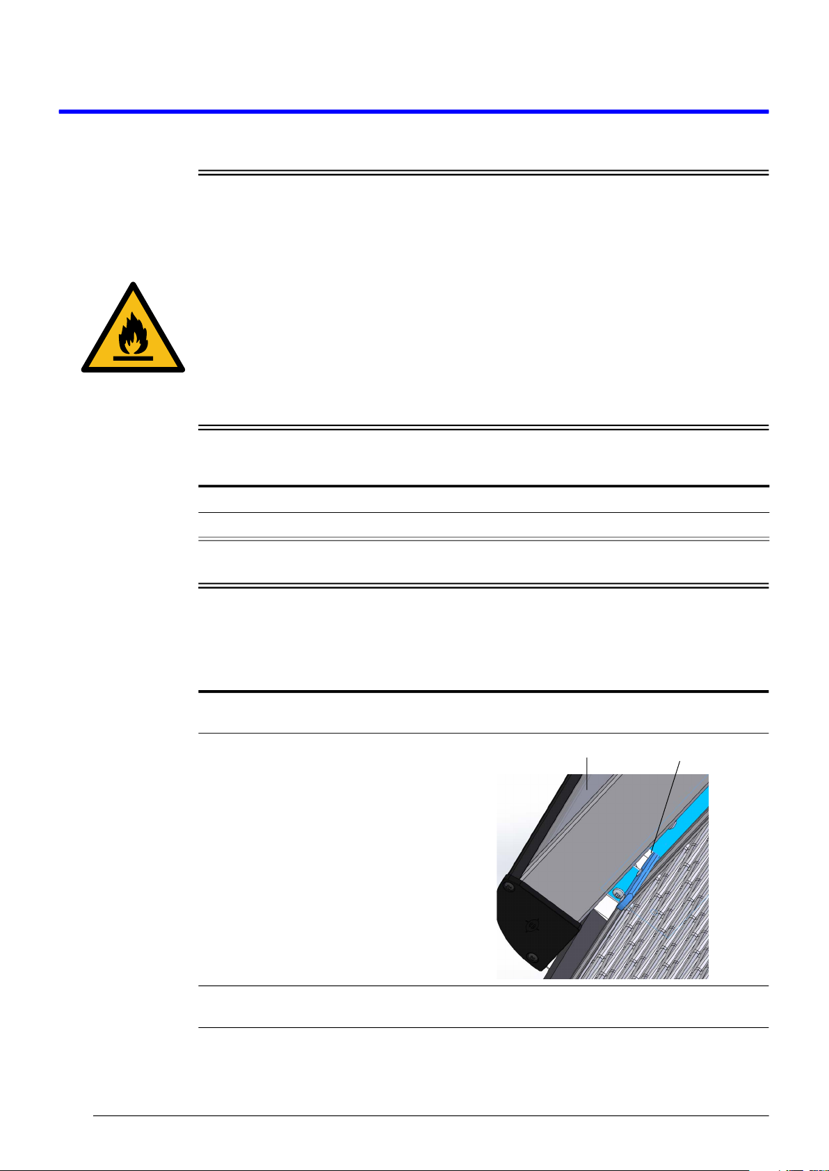
Procedure 6: To fit and remove the security grille
1. Position the security grille (with the tags at the top and locks on the sides) into the top of the
cabinet opening.
2. Manoeuvre the security grille into position so
that both tags at the top of the grille fit into the
slots under the night blind bracket.
3. Position the bottom of the grille to align both the security lock bolts with the holes on the top of the
kick panel.
Security grille tag
Sign assembly

19
SKOPE OD1100N
Replacement Procedures
Service Manual
Kick Panel
The cabinet is fitted with a kick panel that hooks onto the front of the cabinet.
Sign
The OD1100N Low Sign model comes with the sign assembly fitted to the cabinet. For transit
purposes, the OD1100N standard High Sign model has the sign assembly fitted temporarily to
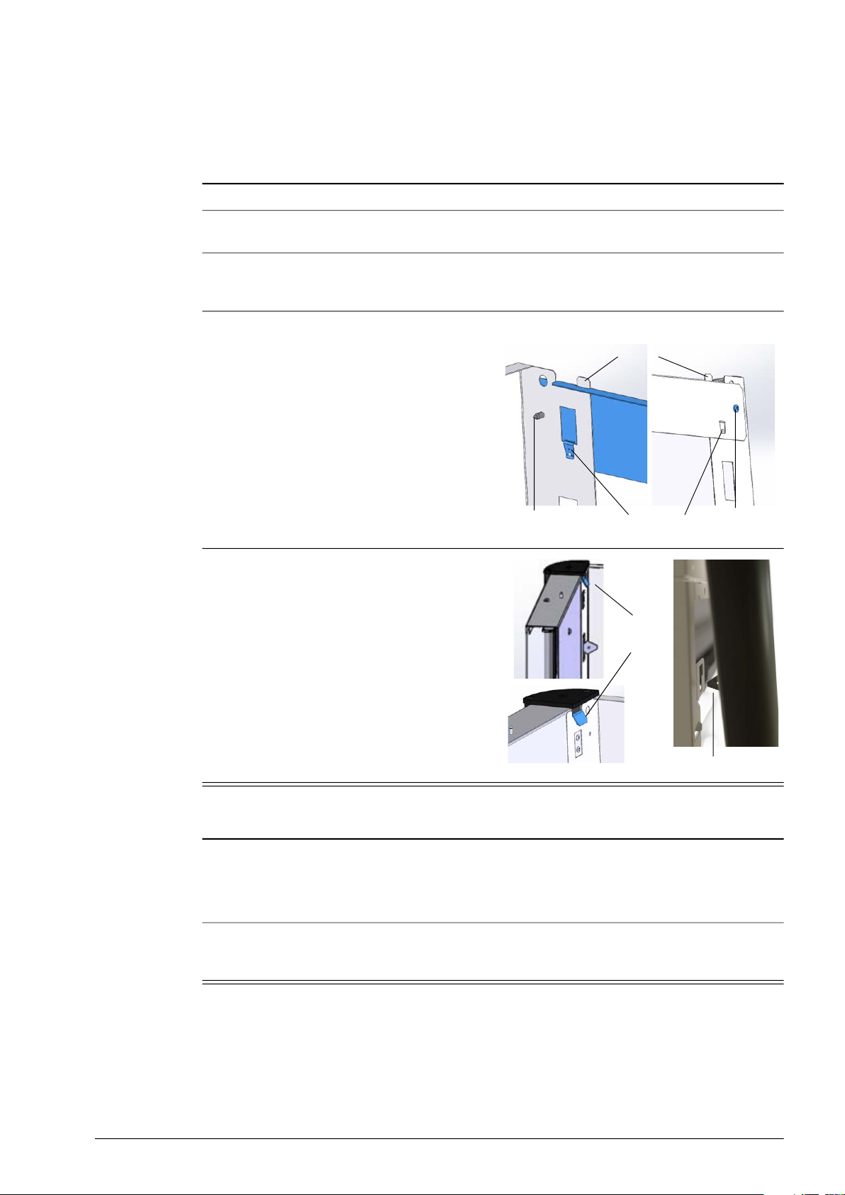
4. Engage both the lock bolts and lock with the
security key (see below).
5. To remove the security grille, reverse the fitting instructions (steps 1 to 4 above).
Procedure 7: To remove the kick panel
1. Disconnect the cabinet from the power supply (see page 18).
2. Remove the two screws from the bottom of the
front panel.
3. Lift the panel up and off the cabinet.
Procedure 8: To refit the kick panel
1. Lift the kick panel over and on to the retainer.
2. Fasten the two screws to the bottom of the kick panel.
Procedure 6: To fit and remove the security grille (continued)
Security grille lock
Security grille
20 Replacement Procedures
Service Manual
SKOPE OD1100N
the cabinet, and the two side panels and rear panel packaged together in the cabinet. The high
sign needs to be fitted to the cabinet on site.
Fitting and
Removing the
Sign Procedure 9: To fit the high sign to the cabinet
1. Remove the high sign assembly from the cabinet.
2. Unpack the sign’s side and rear panel package. There should be three pieces: two identical side
panels, and one rear panel.
3. Loosen the four retaining screws on the roof of the cabinet and fit each sign side panel over the
screws. Slide the sign side panels forward flush with the front of the cabinet, and tighten all four
retaining screws.
4. Fit the rear panel.
•Remove the two screws from the back of
the side panels.
•Fit the rear panel across the back of the
side panels by putting the tabs of the side
panels into the top slots of the rear panel,
and clipping each end tag of the rear panel
into the retaining slot in the side panels.
•Fix the two screws back into each side of
the rear panel to mount it on the side
panels.
5. Attach the high sign assembly onto the
cabinet.
•Clip the top of the sign into the retaining
slots at the top of both side panels.
•Clip the diamond-shaped catches at
bottom of the sign into both the bottom
retaining brackets.
Procedure 10: To remove the sign from the cabinet
High sign only
1. Undo the two screws and unclip the two end tags of the sign rear panel from each side panel.
2. Remove the rear panel.
3. Loosen the four retaining screws on the roof of the cabinet.
High and low sign
4. Pull the bottom of the sign forward, and lift the sign up to disengage from the top retaining slot and
bottom diamond-shaped catches on each side of the cabinet.
Back of rear panel Front of rear panel
Side panel slots
Rear panel tag
Screw Screw
Diamond-shaped catch
Retaining
slot
Other manuals for OD1100N
2
Table of contents
Other Skope Commercial Food Equipment manuals


Popular Commercial Food Equipment manuals by other brands


SandenVendo
SandenVendo HFD000006 Technical & service manual

EMPERO
EMPERO EMP.7SE010 instruction manual

Angelo Po
Angelo Po 1G1BR1G Use and installation manual

Angelo Po
Angelo Po 091CP1G Use and installation manual

Structural Concepts
Structural Concepts BLEND NM4855DSSV user manual

Tetra Pak
Tetra Pak HOYER COMET C manual

MINERVA OMEGA
MINERVA OMEGA FIM 250 operating instructions

Roller Grill
Roller Grill SBM 40 M Instructions for installation and use

Nordcap
Nordcap TG-3 Instructions for use

Skymsen
Skymsen EL3 instruction manual

Lotus
Lotus BS-94EM Instructions for installation and use

First Choice
First Choice VIZU VI014HHC manual