Sky Climber SKY STAGE ULTRA User manual
KY CLIMBER
®
SKY STAGE ULTRA®
USER MANUAL
EE3600A
ED 2018.08.03
N.V. Sky Climber Europe, S.A.
K.M.O. Zone Itterbeek
Nijverheids Straat 23
Duffel B 2570 Belgium
Tel +32 (0) 3 887 81 20
+32 (0) 887 09 94
Fax +32 (0) 3 887 09 94
www.skyclimb r.com
Sky Climber, LLC
1800 Pittsburgh Drive
Delaware, Ohio 43015
Tel (740) 203-3990
(800) 255-4629
Fax (740) 203-3901
SKY STAGE
ULTRA
USER
MANUAL

KY CLIMBER
2
®
SKY STAGE ULTRA®
USER MANUAL
EE3600A
ED 2018.08.03
© Sky Climber®, 2002
All rights reserved. No part of this publication may be reproduced, stored in a retrieval system, or transmitted, in any form or by any means,
electronic, mechanical, photocopying, recording, or otherwise, without the prior written permission of the publisher.
FOREWORD
Welcome to Sky Climber®.
Congratulations on your new Sky Climber® product. All Sky Climber® products are designed
and certified to the highest worldwide industry standards. Our continuous quality control ensures
this product is manufactured to the relevant codes. onetheless, all of this work and effort can
be and is nullified by improper use.
It is vitally important that you and each and every person who is to utilize the Sky Climber®
product, take the time to learn the proper and safe methods relating to utilization of the Sky
Climber® product. Safety begins with a familiarization with the functions and limitations of the
Sky Climber® equipment. It is your responsibility to READ A D U DERSTA D the contents of
this manual. If you have any questions whatsoever, contact your dealer or Sky Climber® cus-
tomer service. It is our desire and intention to provide answers to your question regarding the
proper use of Sky Climber® products. Sky Climber® cannot and will not under any circum-
stances be responsible in any way for injuries or damage sustained as a result of misuse or
misapplication of the product. Please consult your sales materials to determine other applicable
limitations of liability.
Sky Climber®s user manual will guide you through installation and operation procedures.
Sky Climber® reserves the right to continually improve its products. Every effort has been made
to make this manual as accurate as possible at the time of publication; however, there may be
product changes which are not detailed in the manual. Please contact your dealer or Sky
Climber® customer service on a regular basis to obtain follow up information and materials.
Each manual is also available as a PDF (portable document format). A PDF user manual can
be used to look up the correct spare part on a computer screen. With the use of the Contents,
you can quickly jump to the correct page by clicking on the contents line or bookmark. You can
recognize other links by blue markings.
We remind you to always wear personal fall protection equipment and to make sure that all
persons utilizing the product are fully familiar with its features, including safety features and
limitations, such as weight limitations.

KY CLIMBER
3
®
SKY STAGE ULTRA®
USER MANUAL
CONTENTS SKY STAGE ULTRA
SKY STAGE ULTRA.................................................................................................................. 1
FOREWORD ......................................................................................................................... 2
CO TE TS ........................................................................................................................... 3
Safety Guidelines................................................................................................................... 4
Operators Safety.......................................................................................................................4
Operation Safety .......................................................................................................................4
Environment ...............................................................................................................................5
Sky Stage Ultra® with End Stirrup configurations..................................................................... 6
Overview ...................................................................................................................................6
Dimensions ................................................................................................................................7
Transport & Handling eights .....................................................................................................7
Standard Configurations & Assembly Parts ...................................................................................8
Standard Configurations & Load Ratings per UL ..........................................................................9
ork Cages .............................................................................................................................10
Standard Configurations & Load Ratings per EN1808 ................................................................11
Installation Instructions ........................................................................................................ 12
Assemble platform ....................................................................................................................12
Dis-assemble platform ..............................................................................................................15
Use - operation ................................................................................................................... 15
all-rollers ..............................................................................................................................15
Repositioning platform .............................................................................................................15
Cantilevered Stage Assembly................................................................................................ 16
Assemble End Gate ..................................................................................................................16
Assemble alk Through............................................................................................................16
Multiple-Point Stages ............................................................................................................ 17
Straight-line configurations .......................................................................................................17
Angled configurations...............................................................................................................17
Check Lists .......................................................................................................................... 19
Inspection prior to installation ...................................................................................................19
Inspection after installation .......................................................................................................19
Logbook.............................................................................................................................. 20
Instruction to the owner .............................................................................................................20
EE36001
ED 2018.08.03

KY CLIMBER
4
®
SAFETY GUIDELINES
GENERAL
EE36001
ED 2018.08.03
Safety Guidelines
Operators Safety
All persons who service, install, dismantle or use
suspended access equipment must fully comprehend and
act in accordance with this manual and all appropriate
regulations. A competent person is a designated person,
suitably trained, qualified by knowledge and practical
experience to carry out the required task safely.
Training, manuals and other documentation are available
at Sky limber®. Do not hesitate to contact us for more
details.
Operators must be emotionally and physically able to
withstand the stress of working at elevations. Do not work
at elevations if subject to seizures or loss of physical
control. Operators must be safety conscious, responsible
and not under the influence of alcohol, drugs or other
substances.
All persons using suspended access systems must at
all times wear safety harnesses attached by lanyards and
rope grabs to independent lifelines. Use short lanyards
Never use suspended access systems for transporta-
tion of passengers from one level to another.
Keep the vertical travel zone of the platform free of
obstructions. When running into an obstruction immedi-
ately stop the platform. Inspect the platform and the
obstruction for possible damage and/or hang-up. Pro-
ceed in a safe direction. Take care not to overload the
system or get in slack rope situations when running into
an obstacle.
Beware of obstacles when there is too small of a
clearance between platform and façade. Use long-
handled tools when working at large distances between
platform and façade.
Do not handle suspended loads in conjunction with
suspended platforms.
When leaving a suspended platform (in mid-air) first
secure the platform to the face of the structure in order
to keep it from moving away. Do not forget to disconnect
the platform from the structure before lifting or raising,
otherwise serious injuries and/or damage can occur.
Hazardous situations occur when it is not possible to
lower platform to a safe position, ex. over water and
public roads.
Never alter equipment once the platform is sus-
pended. Keep all equipment out of reach of unauthor-
ized persons.
Rejected equipment must be destroyed prior to
disposal so that it can not be misused, reused, or other-
wise returned to service.
and attach the rope grabs as high on the lifeline as
practically possible. Lifelines shall be fastened to a fixed
anchorage other than the rigging systems. Do not
disconnect or remove harnesses or lanyards until safely
on the ground or until completely disembarked from
suspension system to a safe location.
Safety helmets should be worn at all times when
servicing, (dis-) assembling or using the equipment.
Provide protection for operators from collision with
overhead obstacles and falling objects.
Provide adequate protection below the suspended
system to prevent injury to persons from falling objects.
Keep all persons from beneath suspended platforms.
Maintain contact with your supervisor at all times.
Make a copy of this manual available to every person
using, erecting and assembling this equipment.
Never work alone on suspended access systems
Do not over load the equipment
Operation Safety
All suspended access equipment must be handled
with care: during handling of equipment, installation and
use (place loads gently on platform).
Inspect and test the equipment before use, rigging,
re-rigging, after de-rigging and at regular intervals to
make sure that it is maintained in a safe workable
condition. The supervisor should assign a competent
person for inspection purposes. In case of equipment
failures or difficulties noticed during testing and inspec-
tion prior to use, contact your nearest Sky limber®
representative and do not use the equipment until it is
repaired or replaced. Only use Sky limber® spare
parts. Do not alter any equipment. Maintenance may
only be carried out by Sky limber® representatives.
Verify if all decals and nameplates are properly
affixed and legible. If they are obscured or missing,
replacements are available from Sky limber®.
Always verify if a platform is properly counter-
weighted: check the rigging systems prior to each shift.
Never load the platform above the indicated safe
working load.
In case of an emergency during operation press the
red emergency stop button on the hoist or control unit.
The platform will halt immediately (power is cut off,
brakes are activated). Solve the problem first, prior to
further use.
Do not use hoists in conjunction with cableless control
systems.
KY CLIMBER
5
®
SAFETY GUIDELINES
GENERAL
EE36001
ED 2018.08.03
Environment
onsider and control the specific risks related to certain environments and nature of the job. Increase inspection accord-
ingly.
Hazards
Do not use suspended access equipment in severe
conditions: extreme environmental conditions, corrosive
environment, strong magnetic fields, explosive atmos-
pheres.
Do not use suspended access equipment when
handling loads could lead to dangerous situations: molten
metal, acids/bases, radioactive materials, brittle loads.
Wind Speeds
Use adequate restraints when lifting height exceeds
40m (131) with wind speeds above 50km/h = 14m/s
(31mph).
Do not use suspended access equipment when
hazards could arise from wind pressure acting on loads
having a surface area in excess of 2m² (21.5 SQFT).
With the occurence of high winds the platform should
either be lowered to the ground or raised to the roof top
and secured.
Do not use suspended access equipment when wind
speed exceeds 50km/hour
High voltage power-lines
Refer to regulations, federal, state and local codes
when working in the vicinity of electrical overhead
power-lines. onsult the local power company for safe
operating procedures.
The minimum separation between live power lines
and platform is 3m (10).
Touching live power-lines may result in death or
serious injury.
Group 2A
Welding
During welding, the electrocution hazard and the risk of the welding current passing through the steel wire ropes shall be
eliminated by taking the following precautions:
be guided and/or retained so that it does not become
grounded.
over each hoist, Sky Lock and wire winder with
protective covers made out of insulating material.
onnect a ground conductor from platform to work
piece. The size of this conductor shall be equal to or
greater than the size of the stinger lead. It must be a
secondary conductor and shall not be in series with the
primary conductor between welder and work piece.
Use insulated thimbles at each suspension point.
Insulate surplus steel wire rope stored on roof to prevent
grounding or, terminate steel wire rope at insulated
thimble.
over steel wire rope above hoist and Sky Lock for a
distance of ± 1.2m (4) with insulating material: rubber
hose taped in place. Insulate tail line below hoist: extend
downward sufficiently to prevent contact with platform.
The portion of tail line hanging free below platform must
Group 2B
Marine environment
Salty environments may deteriorate aluminum & steel
components. Frequently inspect equipment.
Group Category Condition Temp. Applications Inspection
1 - Normal > 0° /32 F Inspections, light maintenance, window washing. Prior to each workshift.
2 A ontaminated > 0° /32 F Abrasive materials: sand, grit, dust, welding. Prior to each workshift.
B ontaminated > 0° /32 F austic materials: corrosive chemicals, Every 3 hours.
salty environment, acids or fumes.
ontaminated > 0° /32 F Adhesive materials: cement, plaster, paint,
caulking, compound.
3 - Freezing
≤
0° /32 F All Prior to each workshift.
Every hour.
Excess material accumulation
Make sure that excess material does not clutter up the
hoist, Sky Lock or platform.
KY CLIMBER
6
®
END STIRRUP CONFIGURATIONS
SKY STAGE ULTRA®
EE36002
ED 2018.08.03
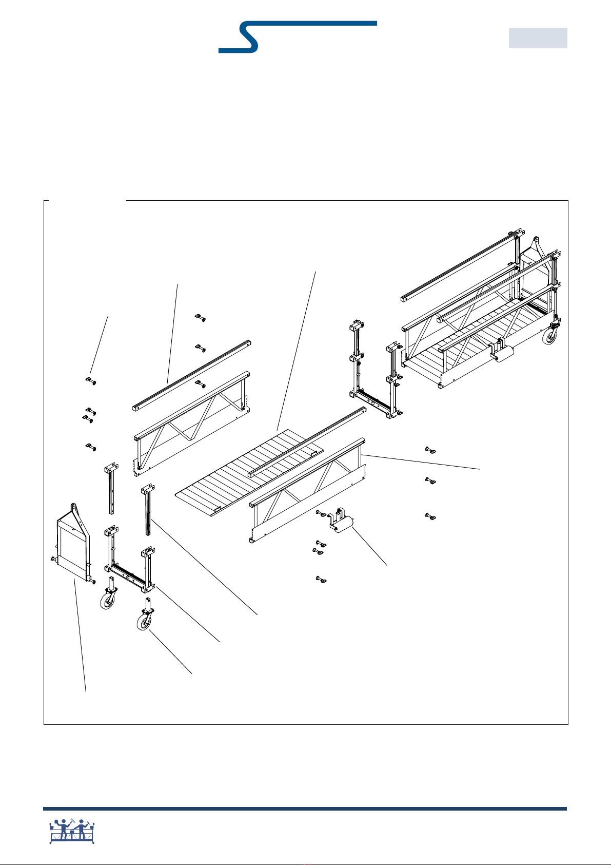
Sky Stage Ultra® with End Stirrup configurations
End Stirrup assy
Telescopic Post
Connecting Frame
Caster assy
Wall Roller assy
Side Panel
Top Rail
Connecting Pin assy
Overview
Floor Panel
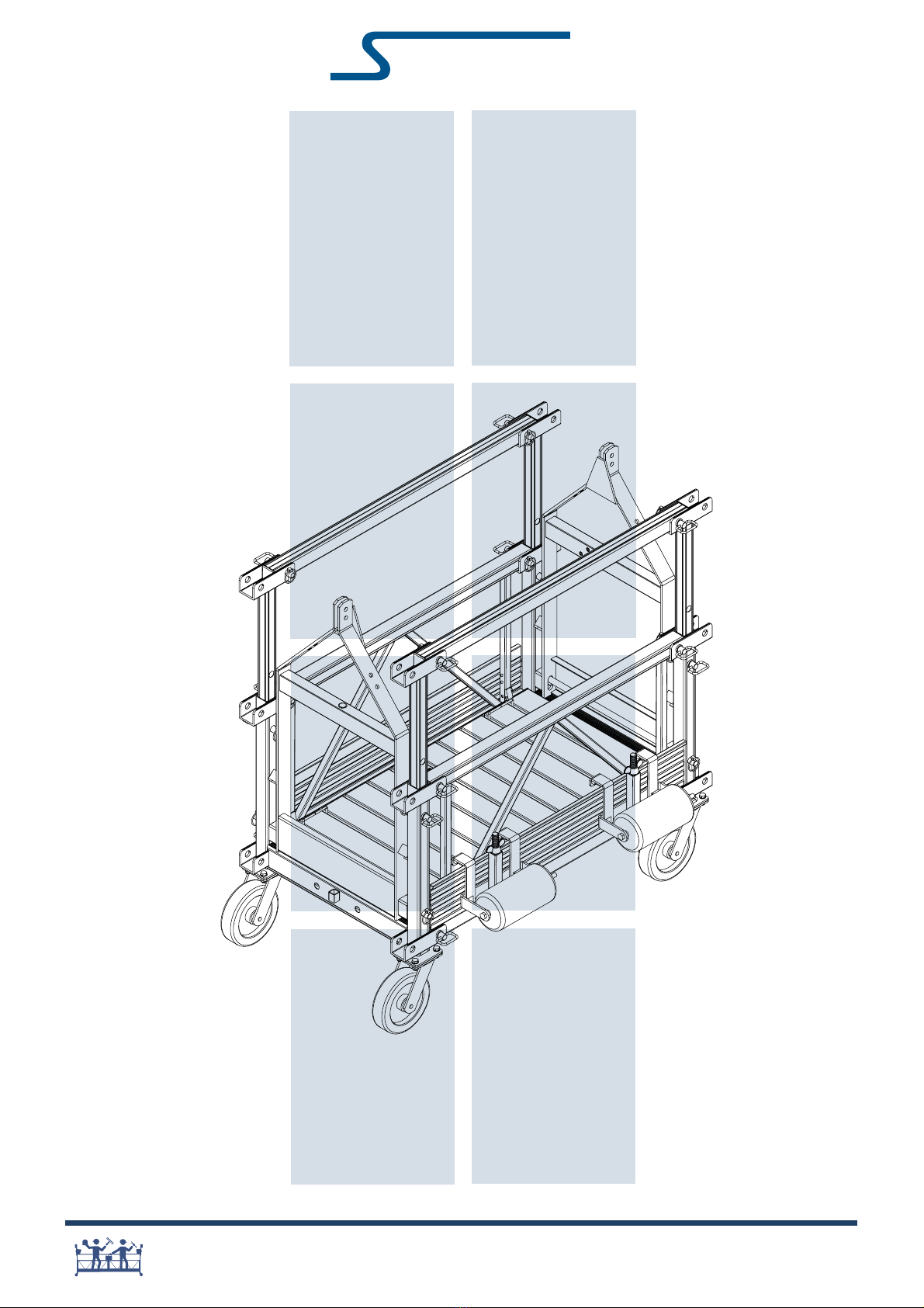
Sky Stage Ultra® is a modular work platform. All compo-
nents are welded out of high quality aluminum. The
platform length can vary between 2m and 15m assem-
bled from 1m, 1.5m, 2m and 3m sections. A section
consists of 2 side panels, a floor panel and 2 top rails.
A rigid structure is formed by attaching sections to
connecting frames with connecting pins.
Top rails are telescopic on both sides of the stage.
The standard configurations are further described.
KY CLIMBER
7
®
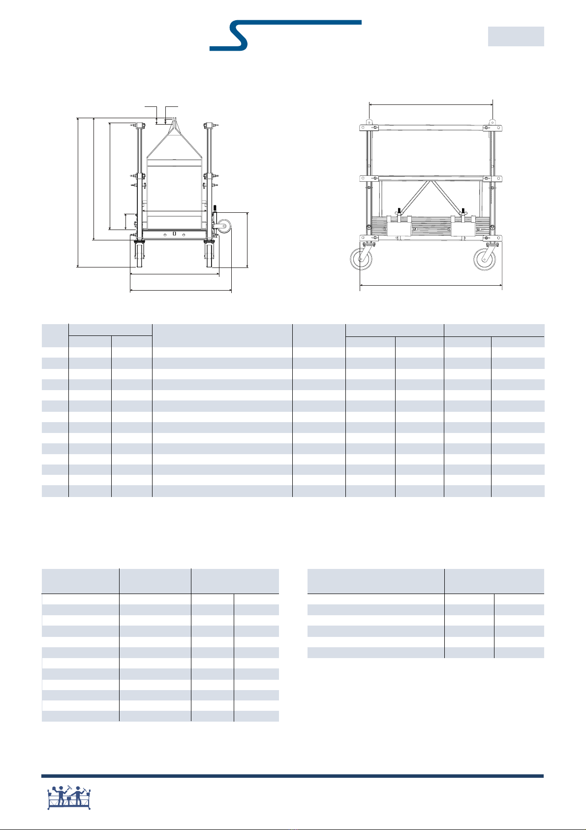
Dimensions
Sky Stage Ultra® with End Stirrup: side view. Sky Stage Ultra® with End Stirrups: front view.
Platform length dimensions are only valid if standard configurations are used (see onfigurations & Assembly Parts).
aster wheel swings 9cm (3.5) outside total length of platform (L1).
Transport & Handling Weights
END STIRRUP CONFIGURATIONS
SKY STAGE ULTRA®
EE36002
ED 2018.08.03
Item Dimension Description Platform Total length (L1) Suspension dist. (L2)
etric Inches length etric Ft/Inch. etric Ft/Inch.
H1a 1.40 m 54 .8 Max. height: platform on surface 2 m 2.23 m 7 3 2.06 m 6 9
H1b 1.43 m 56 .2 Max. height: suspended platform 3 m 3.15 m 10 4 2.98 m 9 9
H2a 1.14 m 44 .8 Idem H1a but without casters 4 m 4.29 m 14 0 4.12 m 13 6
H2b 1.18 m 46 .2 Idem H1b but without casters 5 m 5.21 m 17 1 5.04 m 16 6
H3a 1.00 m 39 .4 Top Rail height from floor panel 6 m 6.13 m 20 1 5.95 m 19 6
H3b 1.10 m 43 .3 Idem H3a: second option 7 m 7.27 m 23 10 7.09 m 23 3
H40.15 m 5 .9 Toeboard height 8 m 8.19 m 26 10 8.01 m 26 3
H50.50 m 19 .5 Stepping height 9 m 9.11 m 29 10 8.93 m 29 3
W10.94 m 37 .0 Max. outside width with wall roller 10 m 10.25 m 33 7 10.07 m 33 0
W20.83 m 32 .5 Max. outside width with safety pins 11 m 11.16 m 36 7 10.99 m 36 0
W30.60 m 23 .6 Inside width: passage 12 m 12.08 m 39 7 11.91 m 39 0
160.00 mm 2 .362 Position: hoist attachment 13 m 13.22 m 43 4 13.05 m 42 9
231.50 mm 1 .240 Position: hoist attachment 14 m 14.14 m 46 4 13.97 m 45 9
15 m 15.06 m 49 4 14.89 m 48 9
Platform Options Self-weight Platform Parts Self-weight
Parts kg lbs kg lbs
Side Panel 1 m 6.4 14 End Stirrup assy 14.5 32
1.5 m 9.1 20 onnecting Frame 4.5 10
2 m 11.8 26 Telescopic Post 0.9 2
3 m 16.8 37 onnecting pin assy 0.3 0.75
Top Rail 1 m 1.4 3 aster assy 4.1 9
1.5 m 1.8 4 Wall Roller assy 4.5 10
2 m 2.3 5
3 m 3.2 7
Floor panel 1 m 6.8 15
1.5 m 9.5 21
2 m 12.2 27
3 m 16.8 37
H1a
H5
C1
W3
W2
W1
H4
H3b
H3a
H2b
H2a
H1b
C2
L1
L2
Handle all parts with care: do not drop or throw parts.
Inspect parts prior to installation and use
(see also Inspection Check Lists).
KY CLIMBER
8
®
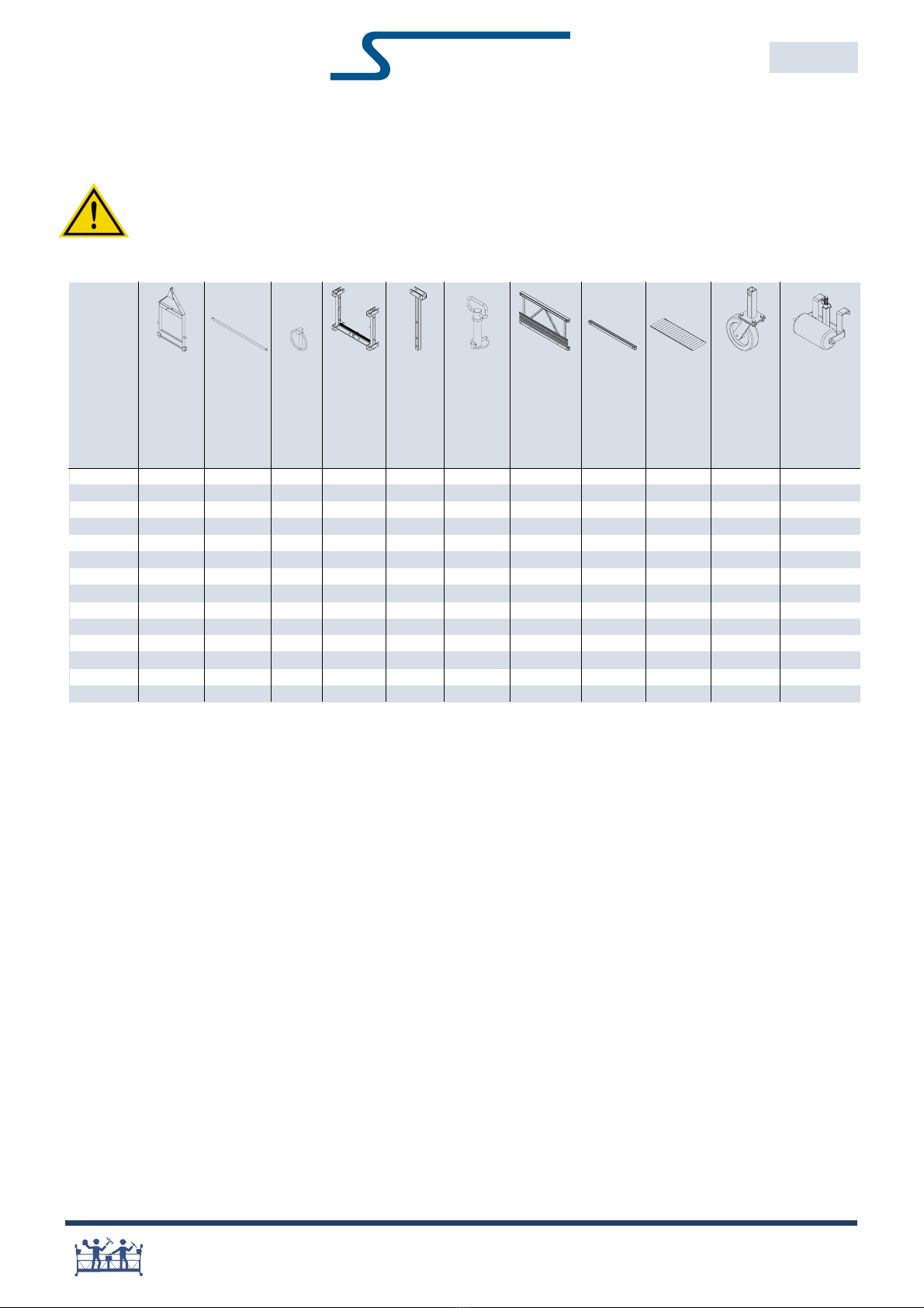
Standard Configurations & Assem ly Parts
The following table can be used as check list when preparing standard configuration for transport.
END STIRRUP CONFIGURATIONS
SKY STAGE ULTRA®
EE36002
ED 2018.08.03
Note: Platform sections may not be used in configurations and lengths other than those shown in these tables. ontact Sky limber®
Engineering to discuss any variations.
1m & 1.5m sections are also available, providing additional versatility in platform length.
ontact your Sky limber® representative for the other configurations.
End Stirrup
Platform length
Caster assy
Top Rail
Rod
Side Panel
Connecting
Pin assy
Telescopic Post
Connecting
Frame
Locking Clip
Wall Roller assy
2m 3m 2m 3m 2m 3m
2m 2 2 4 2 4 16 202010 4 2
3m 2 2 4 2 4 16 020201 4 2
4m 2 2 4 3 6 30 404020 4 2
5m 2 2 4 3 6 30 222211 4 2
6m 2 2 4 3 6 30 040402 4 2
7m 2 2 4 4 8 44 424221 4 2
8m 2 2 4 4 8 44 242412 4 2
9m 2 2 4 4 8 44 606030 4 2
10m 2 2 4 5 10 58 444422 4 2
11m 2 2 4 5 10 58 262613 4 2
12m 2 2 4 5 10 58 080804 4 2
13m 2 2 4 6 12 72 464623 4 2
14m 2 2 4 6 12 72 282814 4 2
15m 2 2 4 6 12 72 0 10 0 10 0 5 4 2
Floor Panel
onformance to the rated load capacities & configurations as shown in these tables is critical to the safe use of Sky Stage Ultra.
Use of other configurations or greater weights could result in serious injury.
KY CLIMBER
9
®
Note: onnecting frame is never to be placed outside intermediate stirrup.
antilever distance is the distance from the suspension point to the end of the stage, not the distance from a part of the
intermediate stirrup to the end of stage
END STIRRUP CONFIGURATIONS
SKY STAGE ULTRA®
EE36002
ED 2018.08.03
5 - 6m 2000 500 - - - - - -
6 - 7m 1500 500 -- -- - -
7 - 8m 1500 500 1500 500 - - - -
8 - 9m 1000 500 1000 500 - - 1000 250
9 - 12m 1000 500 1000 500 1000 500 1000 250
12 - 15m 750 500 750 500 750 500 750 250
Suspended
Distance
Cantilever
Total Stage Cantilever Total Stage Cantilever Total Stage Cantilever Total Stage Cantilever
Rating(lbs) Rating(lbs) Rating(lbs) Rating(lbs) Rating(lbs) Rating(lbs) Rating(lbs) Rating(lbs)
0 - 1m 1 - 1,5m 1,5 - 2m 2 - 3m
Sa e Working Load
1. Determine working load limit (WLL) of hoist.
2. Add WLLs of hoists used.
3. ompare total WLL of hoists less the selfweight of
platform with load rating (LR) of platform.
4. Use lowest value as the Safe Working Load (SWL).
Do not concentrate all loads but equally distribute over total
length of platform.
If loads are concentrated on one half of a platform then the
SWL equals the WLL of 1 hoist less half the self-weight of the
platform (never exceed floor rating).
The load on the floor panels must not exceed the floor rating:
maximum 180kg per meter platform or 120lbs per foot platform.
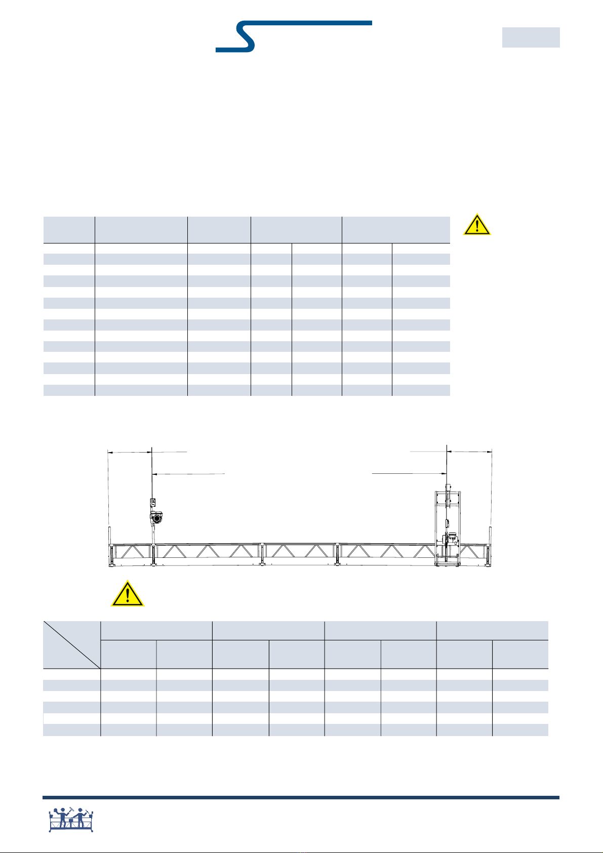
onfigurations for stages with End Stirrups (two point suspension systems) per UL1322.
Platform Configurations Suspension Self-weight Load Rating
Length Distance kg lbs kg lbs
2m 2 6 9 113 249 900 2000
3m 3 9 9 129 285 900 2000
4m 2+2 13 6 164 363 900 2000
5m 2+3 16 6 181 399 900 2000
6m 3+3 19 6 197 435 900 2000
7m 2+3+2 23 3 232 512 680 1500
8m 3+2+3 26 3 249 548 680 1500
9m 3+3+3 29 3 265 584 450 1000
10m 2+3+3+2 33 0 300 662 450 1000
11m 2+3+3+3 36 0 316 698 450 1000
12m 3+3+3+3 39 0 333 734 450 1000
13m 2+3+3+3+2 42 9 368 811 340 750
14m 3+2+3+3+3 45 9 384 847 340 750
15m 3+3+3+3+3 48 9 401 883 340 750
Standard Configurations & Load Ratings per UL
Note: Platform sections may not be used in configurations and lengths other than those shown in these tables. ontact Sky limber®
Engineering to discuss any variations.
onformance to
the rated load
capacities & configurations
as shown in these tables is
critical to the safe use of
Sky Stage Ultra. Use of
other configurations or
greater weights could result
in serious injury.
SUSPENDED DISTANCE
CANTILEVER CANTILEVER
Note: onnecting frame is never to be placed outside intermediate stirrup
KY CLIMBER
10
®
E CASTERS,
.
IF CASTERS
5 AND (4) 360019.
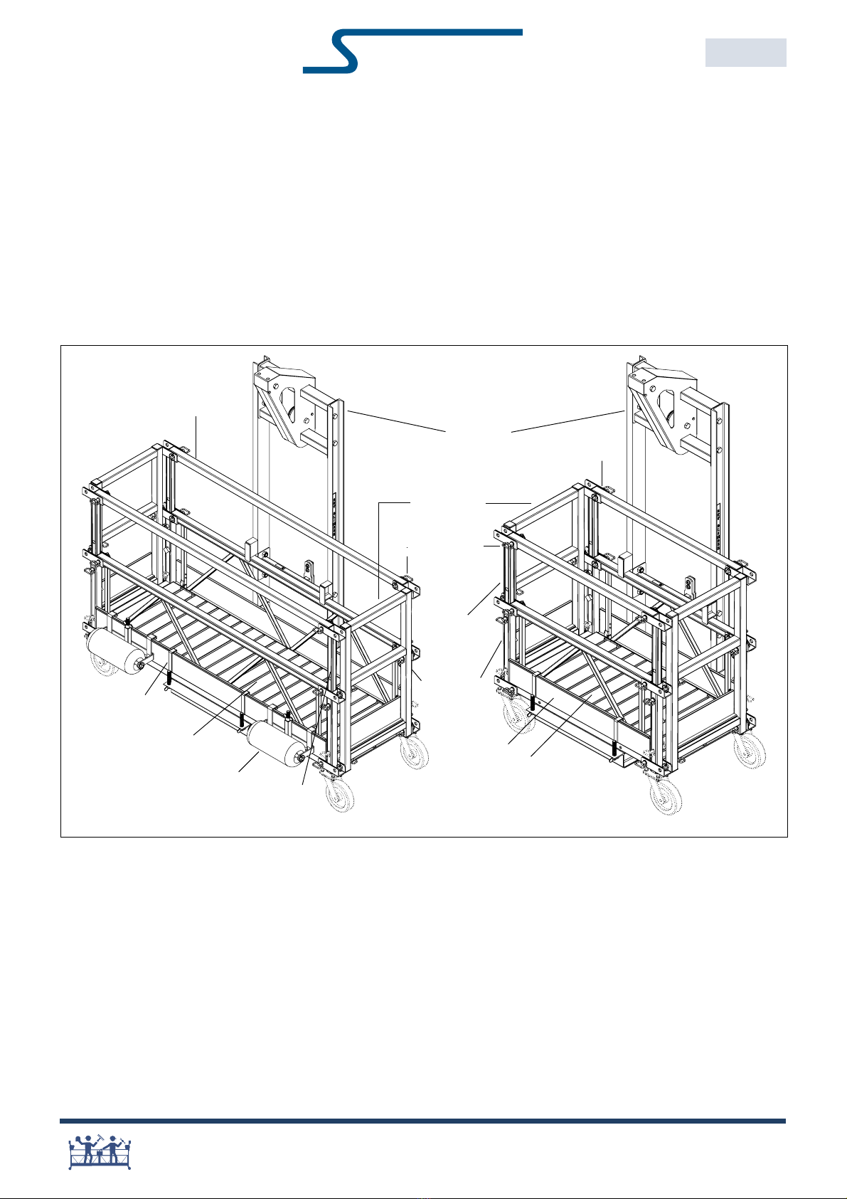
Note: The cages shown do not include casters. If casters are needed, order (4) 360065 and (4) 360019
Work Cages
WORK CAGES
SKY STAGE ULTRA®
EE36002
ED 2018.08.03
Standard Sky Stage Ultra components may be assembled into a workcage configuration.
Workcages utilize only one suspension point, limiting the amount of equipment required.
Workcages may be configured using 1m or 2m components per the detail below.
Maximum stage ratings of 500lbs per end (1000lbs total) are permitted.
For further detail or variations, contact Sky Climber.
3601 8 (2x)
3601 6 (2x)
360130
3601 0 (2x)
360019 (2 x)
36005 ( x)
360039 (2x)
360031 (2x)
3600 0
3600 2
360033 (2x)
360111 (2x)
36005 ( x)
P:RUNFDJH
/RFNSLQ
P6LGHSDQHO
&RQQHFWLQJIUDPH
P)ORRU
7HOHVFRSLFSRVW
:DON7KU VWLUU S
(QG*DWH
P7RSUDLO
P:RUNFDJH
/RFNSLQ
P6LGHSDQHO
&RQQHFWLQJIUDPH
P)ORRU
7HOHVFRSLFSRVW
:DOOUROOHU
:DON7 UXVWLUUXS
(QGJDWH
PWRSUDLO
KY CLIMBER
11
®
Sa e Working Load
1. Determine working load limit (WLL) of hoist.
2. Add WLLs of hoists used.
3. ompare total WLL of hoists less the selfweight of
platform with load rating (LR) of platform.
4. Use lowest value as the Safe Working Load (SWL).
Do not concentrate all loads but equally distribute over total
length of platform.
If loads are concentrated on one half of a platform then the
SWL equals the WLL of 1 hoist less half the self-weight of the
platform (never exceed floor rating).
The load on the floor panels must not exceed the floor rating:
maximum 180kg per meter platform or 120lbs per foot platform.
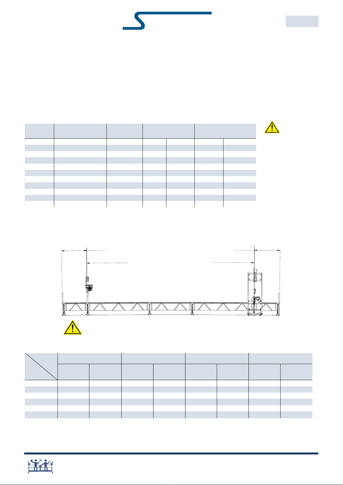
Standard Configurations & Load Ratings per EN1808
Platform Configurations Suspension Self-weight Load Rating
Length Distance kg lbs kg lbs
2m 2 6 9 113 249 360 795
3m 3 9 9 129 285 540 1190
4m 2+2 13 6 164 363 720 1585
5m 2+3 16 6 181 399 900 1985
6m 3+3 19 6 197 435 1080 2380
7m 2+3+2 23 3 232 512 1080 2380
8m 3+2+3 26 3 249 548 1080 2380
9m 3+3+3 29 3 265 584 1080 2380
10m 2+3+3+2 33 0 300 662 920 2028
11m 2+3+3+3 36 0 316 698 750 1650
12m 3+3+3+3 39 0 333 734 680 1500
onfigurations for stages with End Stirrups (two point suspension systems) per EN1808.
END STIRRUP CONFIGURATIONS
SKY STAGE ULTRA®
EE36002
ED 2018.08.03
Note: Platform sections may not be used in configurations and lengths other than those shown in these tables. ontact Sky limber®
Engineering to discuss any variations.
SUSPENDED DISTANCE
CANTILEVER CANTILEVER
5 - 6m
6 - 7m
7 - 8m
8 - 9m OMING SOON
9 - 12m
12 - 15m
Suspended
Distance
0 - 1m 1 - 1,5m 1,5 - 2m 2 - 3m
Total Stage Cantilever Total Stage Cantilever Total Stage Cantilever Total Stage Cantilever
Rating(lbs) Rating(lbs) Rating(lbs) Rating(lbs) Rating(lbs) Rating(lbs) Rating(lbs) Rating(lbs)
Cantilever
Note: onnecting frame is never to be placed outside intermediate stirrup.
antilever distance is the distance from the suspension point to the end of the stage, not the distance from a part of the
intermediate stirrup to the end of stage
onformance to
the rated load
capacities & configurations
as shown in these tables is
critical to the safe use of
Sky Stage Ultra. Use of
other configurations or
greater weights could result
in serious injury.
onnecting frame is never to be placed outside intermediate stirrup
KY CLIMBER
12
®
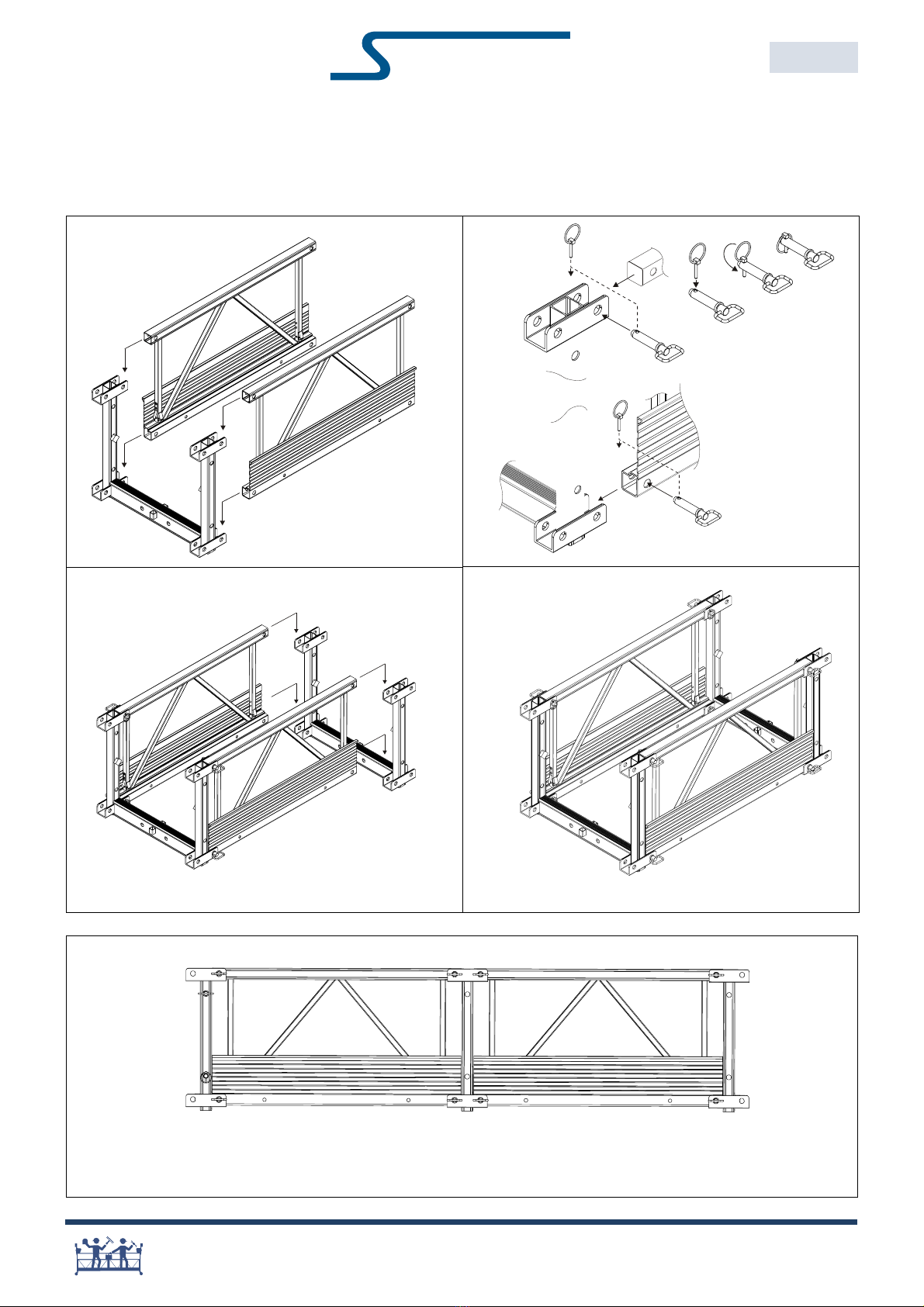
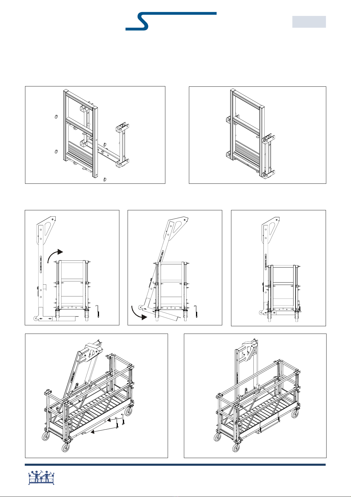
Installation Instructions
Assem le platform
1
34
2
Repeat step 1-4 for longer configuration.
To assemble multiple sections with ease:
place end of platform on blocks.
INSTALLATION INSTRUCTIONS
SKY STAGE ULTRA®
EE36003
ED 2018.08.03
5
Secure each main pin
with a locking clip.
4 onnecting
Pin assys per
Side Panel
KY CLIMBER
13
®
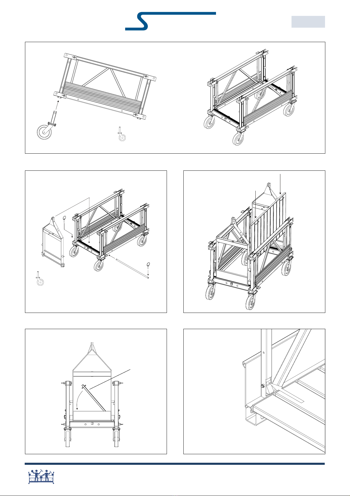
6
7 8
910
INSTALLATION INSTRUCTIONS
SKY STAGE ULTRA®
EE36003
ED 2018.08.03
Minimum 4
are secured with Rod of End Stirrup assy.
Note: Extra asters (not positioned underneath an
End stirrup) can be retained by onnecting Pin assys.
Floor Panel
KY CLIMBER
14
®
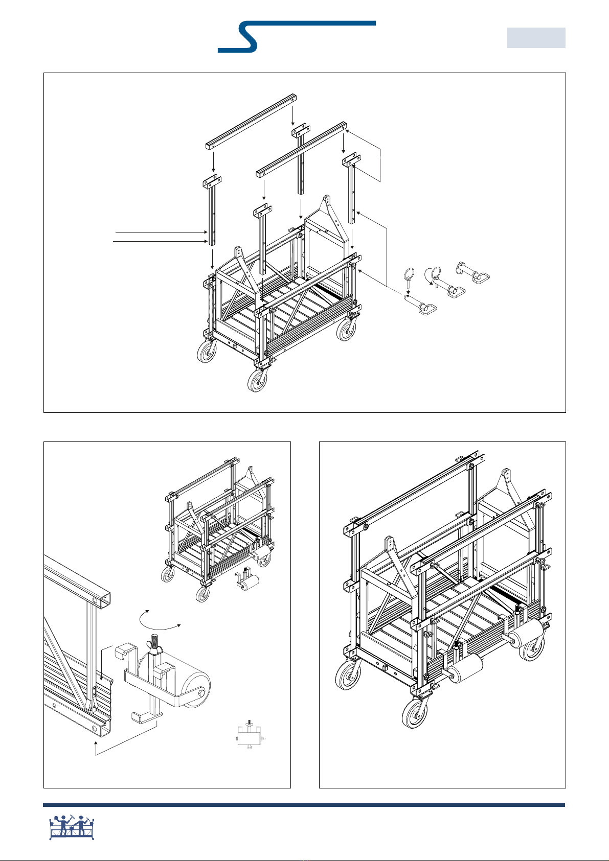
11
Secure each onnecting Pin with the
Locking lip.
2 onnecting Pin assys per Top Rail.
1 onnecting Pin assy per Telescopic Post.
1m above floor
1.1m above floor
INSTALLATION INSTRUCTIONS
SKY STAGE ULTRA®
EE36003
ED 2018.08.03
ongratulations !
You may now attach hoists and safety devices.
Installation shall be checked by a qualified person
prior to use.
A
B
B
C
12
Minimum 2
Note: Once suspended wall rollers can
be repositioned from within platform.
KY CLIMBER
15
®
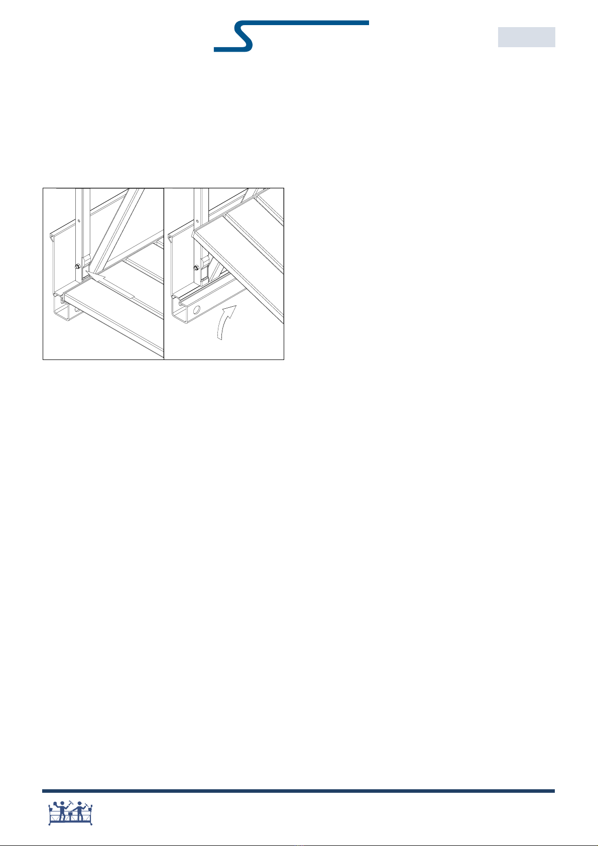
Dis-assem le platform
Reverse assembling procedure to dis-assemble plat-
form.
Floor Panels
Make sure that the floor retainer blocks are inserted into
the side panel prior to lifting the floor panel.
Use - operation
Wall-rollers
Once suspended wall rollers can be repositioned from
within platform.
Repositioning platform
1. Remove all load from platform: material and persons.
2. Dereeve hoists.
3. Reposition platform underneath new position of
rigging system.
4. Reeve hoists.
5. Inspect installation prior to use.
INSTALLATION INSTRUCTIONS
SKY STAGE ULTRA®
EE36003
ED 2018.08.03
KY CLIMBER
16
®
CANTILEVER
SKY STAGE ULTRA®
EE36006
ED 2018.08.03
Assem le Walk Through
Cantilevered Stage Assem ly
Assem le End Gate
KY CLIMBER
17
®
MULTI-POINT STAGES
SKY STAGE ULTRA®
EE36007
ED 2018.08.03
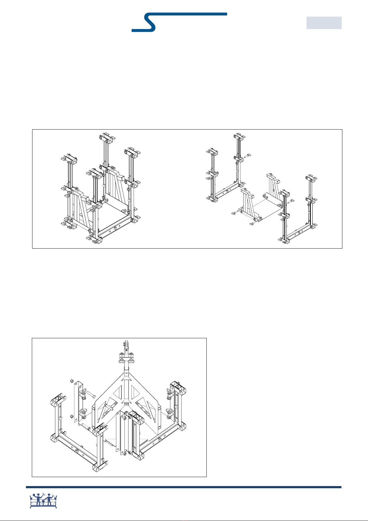
Multiple-Point Stages
Straight-line configurations
Sky Stage Ultra may be used in configurations utilizing more than two hoists in a straight line when used in conjunction
with a Horizontal Hinge. The Horizontal Hinge must always be placed near a central hoist mounted on an intermediate
stirrup. For any specific applications, please call Sky limber Technical Support for a detailed configuration including the
applicable load rating.
Typical Hinge Assy
Angled configurations
Sky Stage Ultra may be used in configurations requiring angles to access odd-shaped walls such as around corners,
balconies, towers, etc. The adjustable corner allows for angles of 0, 5, 10, 15, 30, 45, 51, 60, 72 and 90 degrees. It
also includes a convenient hoist mounting location, rated for hoists up to 1250lb. For any specific applications, please call
Sky limber Technical Support for a detailed configuration including the applicable load rating.
Typical Corner Assy
KY CLIMBER
18
®
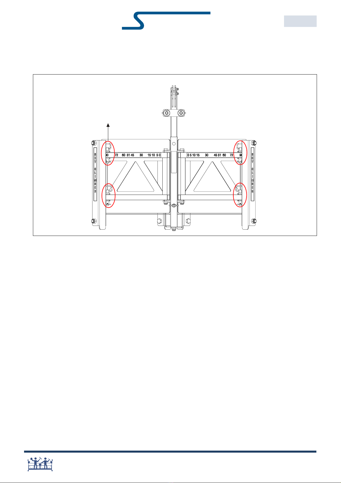
Changing Angles on Adjustable Corner
MULTI-POINT STAGES
SKY STAGE ULTRA®
EE36007
ED 2018.08.03
Locate pins in respective
holes in adjustment arm in
order to achieve desired angle
KY CLIMBER
19
®
CHECK LISTS
SKY STAGE ULTRA®
EE36004
ED 2018.08.03
Always wear personal fall protection equipment.
Verify if all warning decals and rating labels are in place and legible
Verify if provisions are made to protect workers from falling objects above and below
equipment.
Check Lists
Inspection prior to installation
Operating instructions are kept with stage at all times
Reject & replace parts when the following failures are noticed:
Cracked or torn welds.
Cracked or torn material.
Deformations that could endanger the structural strength.
Deformations that would not allow normal installation.
Deformed or cracked connecting holes.
Damaged, missing or ilegible decals indicating load ratings, configurations etc.
Check components prior to shipment
Use table Standard configurations & Assembly Parts in this user manual to verify to correct
amount of parts prior to shipment. Ensure all decals and/or nameplates are in place and
legible.
Inspection after installation
Inspect the platform assembly after installation and prior to each workshift:
Verify load rating per this manual or decals and verify this load will not be exceeded
Verify if all connections have a Connecting Pin assy:
Side Panel: 4 Connecting Pin assys
Top Rail: 2 Connecting Pin assys
Telescopic Post: 1 Connecting Pin assy
Verify if each Connecting Pin is secured with a Locking Clip.
Side Panel: 4 Connecting Pin assys
Top Rail: 2 Connecting Pin assys
Telescopic Post: 1 Connecting Pin assy
Verify if each End Stirrup has 2 secured Locking Clips or connecting Rod.
Verify if Wall Roller assemblies are tightened.
Verify if floor retainer Tabs & Blocks are extended: 4 per Floor Panel.
Verify if stirrups are in line with the roof supports.
KY CLIMBER
20
®
LOGBOOK
SKY STAGE ULTRA®
EE36005
ED 2018.08.03
Always wear personal fall protection equipment.
Log ook
Instruction to the owner
Owner must keep a logbook which contains the following:
ame of the competent person in charge.
Date and name of operator(s).
Serial number of hoist(s) and secondary device(s).
umber of hours equipment in service.
Specification of wire rope.
umber of hours wire rope in use.
Record of any incident and action taken.
Dates of periodic inspection and record of outcome.
Maintenance and repair records shall be kept in logbook.
Other manuals for SKY STAGE ULTRA
1
Table of contents
Other Sky Climber Construction Equipment manuals


