Sky Climber Sky Rig User manual

Print Date: 7/21/2020
SCL_AssemblyInstructions_SkyRig_RevAA_2020
-07-21
Sky Rig
Assembly Instructions
Sky Rig roof rigging, Corner Adaptor, and Beam Splice Tube Packages
Sky Climber LLC.
1800 Pittsburgh Dr.
Delaware, OH 43015
Tel. 1 800-255-4629
www.skyclimber.com

Print Date: 7/21/2020
SCL_AssemblyInstructions_SkyRig_RevAA_20
20-07-21
SAFETY CHECKLIST
TO OWNERS AND DISTRIBUTORS
It is imperative that this manual be given to the erector and/or operator of Sky Climber equipment and that
they read, fully understand, and follow all instructions contained herein.
WARNING
Any use of this equipment, other than in strict accordance with these instructions, shall be at the Operator's
risk and may result in serious injury to themselves or others.
DAILY CHECKLIST
Prior to use, check Sky Climber Hoists, Sky Locks, wire rope and other equipment for wear. DO NOT use hoists or
Sky Locks which are damaged or worn beyond normal tolerances.
Ascertain that:
• Instructions are kept with the unit at all times. Additional copies are available – contact Sky Climber or visit
www.skyclimber.com.
• All Warning and Rating labels are in place, legible, and have been read.
• Roof rigging load is adequately distributed over the roof or parapet.
• Counterweights are non-flowable type, secure and in the correct quantities.
• Cornice hooks, parapet clamps, or outriggers are secured and tied back. Tiebacks are tight and straight back
or two opposing tie-backs are used (contact Sky Climber Engineering for details).
• Wire rope inspected and is not kinked, bird-caged, or otherwise damaged or overly worn.
• Minimum of three (3) J-Clamps / fist grips are used and are properly torqued. (Four J-Clamps are required
for round thimbles).
• Suspended platform hoist is connected to proper power source.
• Hoist drain holes on bottom are open. Check that fasteners are properly installed on air hoists; oil level in
lubricator of hoist is acceptable.
• Sky Lock, Hoist Load, Controlled Descent, and Emergency Stop tests performed and acceptable.
• Make sure ALL fall protection equipment is damage-free and in good condition.
© Sky Climber, 2020. All rights reserved. No part of this publication may be reproduced, stored in a retrieval system, or
transmitted, in any form or by any means, electronic, mechanical, photocopying, recording, or otherwise, without the prior
written permission of the publisher.
SAFETY IS THE RESPONSIBILITY OF BOTH OWNERS AND
OPERATORS OF THIS EQUIPMENT.

Print Date: 7/21/2020
SCL_AssemblyInstructions_SkyRig_RevAA_20
20-07-21
ASSEMBLY INSTRUCTIONS
Sky Climber Sky Rig
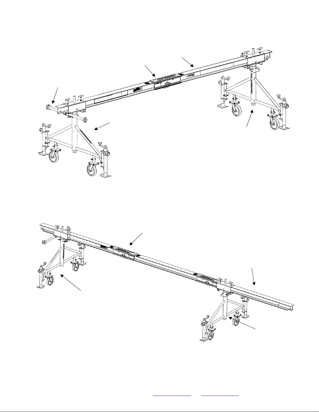
1. Assemble beam using beam tube or splice plates. The 16-foot Sky Rig Package (Part number 3835-ABT)
consists of one 2-foot beam connection tube, two end beams, and two Sky Rig rolling rig dolly assemblies with
casters, jacks, and weight bars.
2. Install casters on Sky Rig Dolly frames and pin in place.
3. Raise the mast to the desired height and insert the retaining pin. Loosen the t-handles on the mast head.
Insert and pin a jack on each side of the stanchion. Repeat with second mast.
4. Install jacks and pin in place.
5. Insert the assembled I-beam through the mast head of the front stanchion until you reach the desired amount
of outreach. Tighten the t-handles. Insert other end of I-beam through the mast head of the rear stanchion
until about 3 inches of the beam extends beyond the mast head (packages 3835-ABT and 3835-BBT).
6. Insert two counterweight bars and pin in place.
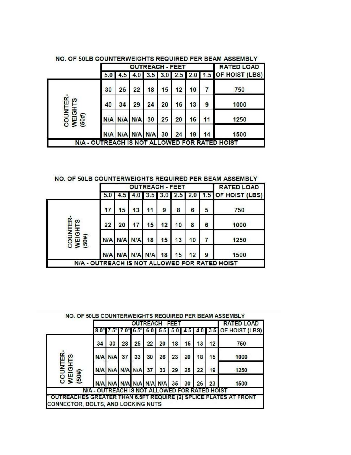
7. Check chart to determine maximum amount of outreach for your application. If a strongback is required see
package 3835-CBT.
8. Roll the assembled Sky Rig into the desired location. Crank the jacks until the load is removed from the casters
and the roof rig is level.
9. Slide the correct number of counterweights (see chart on page 6) onto the longhorn rods. Slide the large
washers onto the rods and place a bale clip or nut and bolt through the ends of the rods to retain the
counterweights.
10. Attach the tie back wire rope to the hole in the rear of the I-beam or the shackle of the suspension rope and
tie back to a substantial building structure*.
*Substantial building structures are defined and verified as an anchor point designed and confirmed in writing by an engineer,
with a 4:1 safety factor versus the rating of the hoist being used.
11. Attach the suspension wire rope assembly to the hole in the front of the I-beam.
Print Date: 7/21/2020
SCL_AssemblyInstructions_SkyRig_RevAA_20
20-07-21
Sky Rig
Dolly
Assembly
Sky Rig Dolly
Assembly
8
-
foot End
Beam
Beam Tube
16-foot Sky Rig (plus
counterweights)
Counterweight
bar
24-foot Sky Rig
Sky Rig Dolly
Assembly
Sky Rig Dolly
Assembly
8
-
foot End
Beam
Beam Tube
Print Date: 7/21/2020
SCL_AssemblyInstructions_SkyRig_RevAA_20
20-07-21
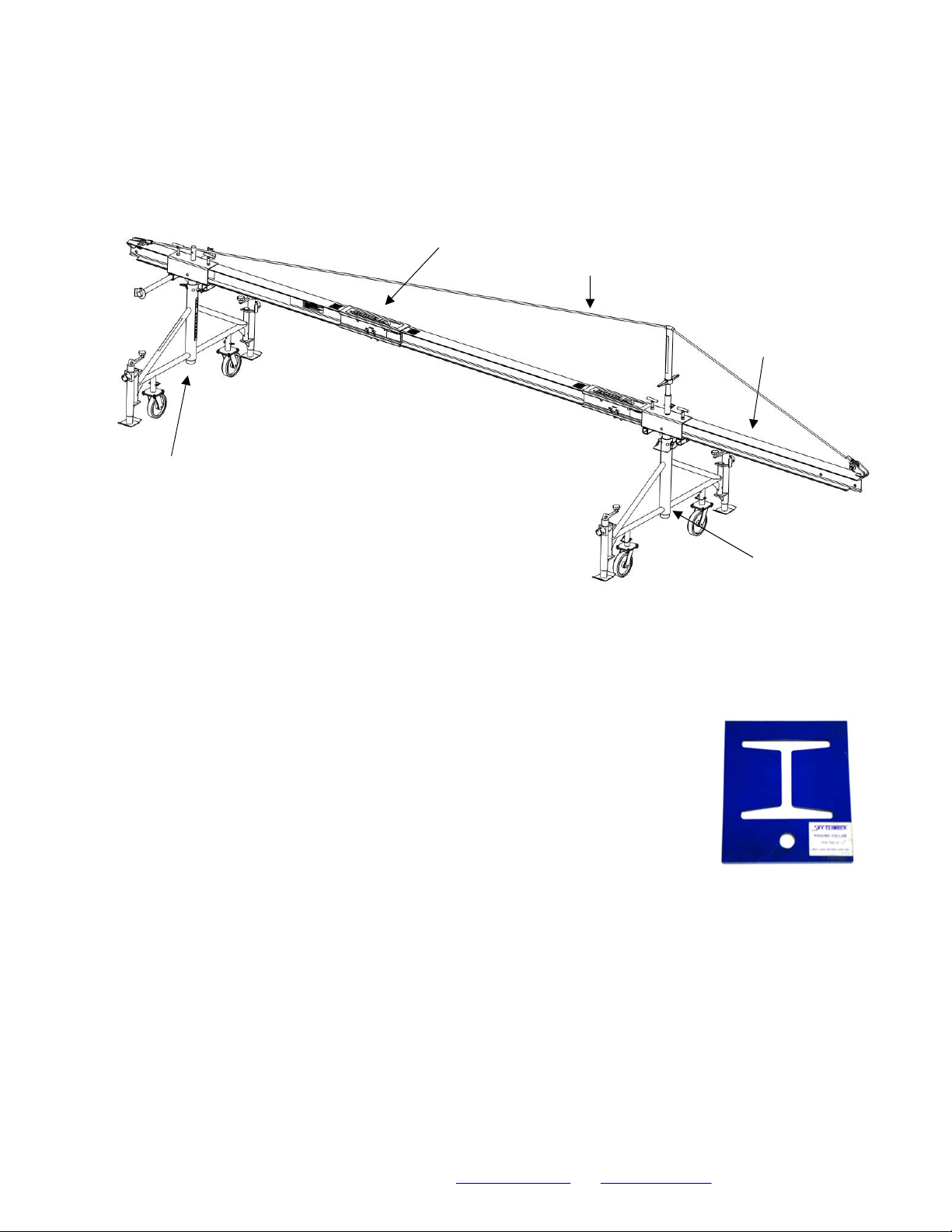
Rigging Collar Instructions
• The Rigging Collar is designed to be used when intermediate and additional
suspension points are required on the Sky Climber Rolling Roof Rig beam. For
example: it may be used to reduce the outreach without moving the entire rolling
roof rig.
• The Rigging Collar may only be used when precautions have been taken to
ensure a shackle, stop bolt or other hardware is placed in the hole at the end of
the beam. Locate the Rigging Collar between the rolling roof rig stanchion and
the end of the beam.
• Counterweight calculations should be based upon the rolling roof rig position i.e. the Rigging Collar may not
be used to reduce outreach with the goal of reducing the number of counterweights required.
24-foot Rolling Roof Rig
WITH Strongback
Rigging Collar
Strongback
Cable
If a strongback is required, move the rear
stanchion 8 inches from the end of the beam.
Attach the strongback mast to the top of the
front stanchion mast head and secure with bale
clips. Place the telescoping section on top of
the mast. Hook the finger hooks on each end
of the cable to the flange on either end of the I-
beam. Turn the wing nut on the telescoping
mast, raising it until the cable is tight.
Sky Rig Dolly
Assembly
Sky Rig Dolly
Assembly
8
-
foot End
Beam
Beam Tube

Print Date: 7/21/2020
SCL_AssemblyInstructions_SkyRig_RevAA_20
20-07-21
Beam Tube Instructions
• Follow normal Rolling Roof Rig instructions but use the Beam Tube in place
of splice plates, nuts and bolts. Insert Pins in the outermost holes of the
beam allowing for assembly without tools.
• Look through the inspection slot to verify that beam is fully inserted into the
beam tube. If you can see through to the inspection slot on the opposite
side of the beam tube, then the beam is not fully inserted.
• Some beams also feature a label that will be partially visible once inserted into
the beam tube. If the green portion of the label is visible but not the red
portion, the beam has been properly inserted. If the red portion of the label is
visible, the beam has NOT been fully inserted into beam tube.
Corner Adaptors
A Corner Adapter reduces outreach by moving the fulcrum closer to
parapet. It also reduces the quantity of counterweights needed and can
eliminate the need for a cable-truss/strongback.
The part number for the Sky Rig Corner Adaptor is 3835-0150. Please
contact Sky Climber for more information on the use and installation of this
product.
Beam Tube
Sky Rig Corner
Adapter
Beam insertion label
Print Date: 7/21/2020
SCL_AssemblyInstructions_SkyRig_RevAA_20
20-07-21
Counterweights
24-foot Sky Rig WITH Strongback
24-foot Sky Rig
16-foot Sky Rig
Table of contents
Other Sky Climber Construction Equipment manuals


