JTS US-903DC PRO/2 User manual

®
Vertrieb von JTS-Produkten — Distribution of JTS products
US-903DC PRO/2
Diversity-UHF-Dual-Empfänger
Diversity UHF Dual Receiver
Récepteur Double UHF Diversity
Receptor Dual UHF Diversity
Bedienungsanleitung
Instruction Manual
Mode d’emploi
Manual de instrucciones

2
Bevor Sie einschalten …
Wir wünschen Ihnen viel Spaß mit Ihrem neuen
Gerät von JTS. Bitte lesen Sie diese Bedie-
nungsanleitung vor dem Betrieb gründlich
durch. Nur so lernen Sie alle Funktionsmöglich-
keiten kennen, vermeiden Fehlbedienungen
und schützen sich und Ihr Gerät vor eventuellen
Schäden durch unsachgemäßen Gebrauch.
Heben Sie die Anleitung für ein späteres Nach-
lesen auf.
Der deutsche Text beginnt auf der Seite 4.
Before switching on …
We wish you much pleasure with your new
JTS unit. Please read these operating instruc-
tions carefully prior to operating the unit. Thus,
you will get to know all functions of the unit, op-
erating errors will be prevented, and yourself
and the unit will be protected against any
damage caused by improper use. Please keep
the operating instructions for later use.
The English text starts on page 10.
DEUTSCHENGLISH
Antes de cualquier instalación ...
Le deseamos una buena utilización para su
nuevo aparato de JTS. Por favor, lea estas ins-
trucciones de uso atentamente antes de hacer
funcionar el aparato. De esta manera conocerá
todas las funciones de la unidad, se prevendrán
errores de operación, usted y el aparato estarán
protegidos en contra de todo daño causado
por un uso inadecuado. Por favor, guarde las
instrucciones para una futura utilización.
La versión española comienza en la página 21.
ESPAÑOL
Avant toute installation …
Nous vous souhaitons beaucoup de plaisir à uti-
liser cet appareil JTS. Lisez ce mode d'emploi
entièrement avant toute utilisation. Uniquement
ainsi, vous pourrez apprendre lʼensemble des
possibilités de fonctionnement de lʼappareil, évi-
ter toute manipulation erronée et vous protéger,
ainsi que lʼappareil, de dommages éventuels
engendrés par une utilisation inadaptée. Con-
servez la notice pour pouvoir vous y reporter
ultérieurement.
La version française se trouve page 16.
FRANÇAIS

3
SET SET
UHF
POWER
PUSH OPEN
US-903DC
Dual Channel PLL Diversity Receiver
PR
O
VOL
MAXMIN
VOL
MAXMIN
GROUP CHANNEL GROUP CHANNEL
AF
RF
AB
GROUP CHANNEL GROUP CHANNEL
AF
RF
A B
MUTE
MUTE
A B
12
34 5 6 7 8 9 10 9 8 7 6 11 3
12 12
ab c d e
13 14 15 16 17 13

4
Auf der ausklappbaren Seite 3 finden Sie alle
beschriebenen Bedienelemente und Anschlüsse.
1 Übersicht der Bedienelemente und
Anschlüsse
1.1 Frontseite
1Bedien- und Anzeigefeld für die Empfangseinheit
CH 1
2Bedien- und Anzeigefeld für die Empfangseinheit
CH 2
3Empfangsantennen
4Ladekontrollanzeigen, jeweils für das linke und
rechte Akkupaar im Akkufach
leuchtet nicht: keine Akkus eingesetzt, Akkus falsch
eingesetzt oder defekt
blinkt: Akkupaar wird geladen
leuchtet kontinuierlich: Akkupaar ist voll geladen
5Akkufach zum Aufladen der beiliegenden Nickel-
Metallhydrid-Akkus (NiMH), die zur Stromversor-
gung der Taschensender und Funkmikrofone
genutzt werden können
6Lautstärkeregler VOL*
7Taste L* zur Aufwärtssuche für Empfangsgruppe/
Kanal (im Gruppen-/Kanaleinstellmodus) und zum
Aktivieren der Sperrfunktion (im Sperreinstellmodus)
8Taste M* zur Abwärtssuche für Empfangsgruppe/
Kanal (im Gruppen-/Kanaleinstellmodus) und zum
Deaktivieren der Sperrfunktion (im Sperreinstell-
modus)
9Taste SET*
bei nicht gesperrtem Gerät:
zum Aufrufen und Verlassen der Einstellmodi für
Empfangsgruppe/Kanal, Sperrfunktion
→Kap. 6.1, 6.1.1
bei gesperrtem Gerät:
zum Aufrufen und Verlassen des Einstellmodus für
die Sperrfunktion →Kap. 6.1.1
10 LC-Multifunktionsdisplay (Abb. 2)
aAnzeige RF* (radio frequency) für die Emp-
fangsstärke des Funksignals: je länger die Bal-
kenanzeige, desto besser ist der Empfang
bAnzeige AF* (audio frequency) für die Laut-
stärke des empfangenen Audiosignals [unab-
hängig von den Lautstärkereglern VOL (6)]: je
länger die Balkenanzeige, desto höher ist der
Lautstärkepegel
cAnzeige* der Empfangsgruppe ( , , oder )
und des Übertragungskanals (1 – 16)
Die zugehörigen Frequenzen sind in der Tabelle
Abb. 4 auf der Seite 7 angegeben.
dEmpfangsanzeigen* und : signalisieren, wel-
che der beiden Antennen das stärkere Funksig-
nal empfängt
eAnzeige MUTE*: signalisiert, dass die zugehörige
Empfangseinheit stumm geschaltet ist, weil kein
oder ein zu schwaches Funksignal empfangen
wird oder beim Funkmikrofon MH-8800G/2 die
Mute-Funktion eingeschaltet ist
11 Ein-/Ausschalter
12 Montagewinkel zum Einsetzen des Empfängers in
ein Geräterack →Kap. 4
1.2 Rückseite
13 BNC-Antennenbuchsen ANT. 1 und ANT. 2 für die
zwei beiliegenden Antennen (3)
14 Ausgänge AF OUTPUT BAL. (XLR, sym.) für das
Ausgangssignal der Empfangseinheit CH 1 und
das Ausgangssignal der Empfangseinheit CH 2,
zum Anschluss an zwei symmetrische Mikrofonein-
gänge z. B. eines Mischpults oder Verstärkers
15 Regler SQUELCH* zum Einstellen der Ansprech-
schwelle für die Störunterdrückung
16 Ausgang des Summensignals der beiden Emp-
fangseinheiten CH 1 und CH 2 (6,3-mm-Klinken-
buchse, asym.) zum Anschluss an einen Line-Ein-
gang z. B. eines Mischpults oder Verstärkers
17 Stromversorgungsbuchse zum Anschluss des bei-
liegenden Netzgeräts
B
A
DEUTSCH
*jeweils für die Empfangseinheit CH1 und die Empfangs-
einheit CH 2

5
2 Hinweise für den sicheren Gebrauch
Die Geräte (Empfänger und Netzgerät) entsprechen
allen erforderlichen Richtlinien der EU und sind des-
halb mit gekennzeichnet.
Beachten Sie auch unbedingt die folgenden Punkte:
GDie Geräte sind nur zur Verwendung im Innen-
bereich geeignet. Schützen Sie sie vor Tropf- und
Spritzwasser, hoher Luftfeuchtigkeit und Hitze (zu-
lässiger Einsatztemperaturbereich 0 – 40 °C).
GNehmen Sie den Empfänger nicht in Betrieb und tren-
nen Sie das Netzgerät sofort vom Stromnetz, wenn:
1. sichtbare Schäden an den Geräten oder an der
Netzleitung vorhanden sind,
2. nach einem Sturz oder Ähnlichem der Verdacht
auf einen Defekt besteht,
3. Funktionsstörungen auftreten.
Lassen Sie die Geräte in jedem Fall in einer Fach-
werkstatt reparieren.
GEine beschädigte Netzleitung des Netzgerätes darf
nur durch den Hersteller oder durch eine Fachwerk-
statt ersetzt werden.
GZiehen Sie den Netzstecker des Netzgerätes nie an
der Zuleitung aus der Steckdose, fassen Sie immer
am Stecker an.
GVerwenden Sie für die Reinigung nur ein trockenes,
weiches Tuch, niemals Chemikalien oder Wasser.
GWerden die Geräte zweckentfremdet, nicht richtig
angeschlossen, falsch bedient oder nicht fachge-
recht repariert, kann keine Haftung für daraus resul-
tierende Sach- oder Personenschäden und keine
Garantie für die Geräte übernommen werden.
3 Einsatzmöglichkeiten und Zubehör
Der Dual-Multifrequenz-Empfänger US-903DC PRO/2
bildet in Verbindung mit zwei passenden Sendern von
JTS ein drahtloses Audio-Übertragungssystem. Durch
die drahtlose Übertragung von Musik oder Sprache
zur Audioanlage behalten die Musiker während des
Auftritts ihre Bewegungsfreiheit. Die Übertragungs-
reichweite hängt von den örtlichen Gegebenheiten ab
und kann bis zu 100 m betragen.
Der Empfänger arbeitet mit „Diversity“-Technik:
Das Sendesignal wird von zwei räumlich getrennten
Antennen empfangen. Eine Elektronik wählt das Sig-
nal mit der besseren Qualität aus und leitet es zu den
Eingängen der Empfangseinheiten weiter.
Für den Empfang stehen vier Sendegruppen (A – D)
mit jeweils 16 Übertragungskanälen zur Verfügung,
d. h. insgesamt also 64 werkseitig eingestellte Über-
tragungskanäle. Diese Kanäle im UHF-Bereich von
740 – 764 MHz können frei ausgewählt werden.
Zum Lieferumfang gehören vier Nickel-Metall-
hydrid-Akkus (1300 mAh), die zur Stromversorgung
von zwei Sendern genutzt werden können und sich
über die integrierte Ladeeinheit bequem aufladen las-
sen.
Es können folgende Sender aus dem Programm von
JTS mit dem US-903DC PRO/2 verwendet werden:
MH-8800G/2 Bestell-Nr. 25.2950
dynamisches Handmikrofon mit integriertem Multifre-
quenz-Sender
PT-920BG/2 Bestell-Nr. 25.2960
Multifrequenz-Taschensender mit Lavaliermikrofon
Zur Erhöhung der Reichweite und der Störsicherheit
können anstelle der beiliegenden Antennen zwei als
Zubehör erhältliche Antennenverstärker UB-900/2
(Bestell-Nr. 15.0750) verwendet werden. Die Verstär-
ker erhalten ihre Stromversorgung über die Antennen-
buchsen des Empfängers.
Beim Einsatz mehrerer Empfänger in der Audioanlage
kann der Antennenverteiler UA-900 (Bestell-Nr.
15.0610) eingesetzt werden. Er liefert auch die Strom-
versorgung für bis zu vier Empfänger.
4 Rackmontage
Der US-903DC PRO/2 ist als Tischgerät oder für den
Einbau in ein Rack für Geräte mit einer Breite von
482 mm (19") vorgesehen. Für den Rackeinbau die
vier Standfüße abschrauben und die beiden beiliegen-
den Montagewinkel (12) mit jeweils zwei Schrauben
vorne an der linken und rechten Seite des Gehäuses
anschrauben.
Sollen die Geräte endgültig aus dem Betrieb
genommen werden, übergeben Sie sie zur
umweltgerechten Entsorgung einem örtli-
chen Recyclingbetrieb.
Werfen Sie defekte Akkus nicht in den Hausmüll,
sondern geben Sie sie nur in den Sondermüll (z. B.
Sammelbehälter bei Ihrem Einzelhändler).
WARNUNG Das Netzgerät wird mit lebensgefähr-
licher Netzspannung (230 V~) versorgt.
Nehmen Sie deshalb nie selbst Ein-
griffe am Netzgerät vor. Durch unsach-
gemäßes Vorgehen besteht die Gefahr
eines elektrischen Schlages.
DEUTSCH
®

6
5 Anschluss
1) Die beiden beiliegenden Antennen (3) in die BNC-
Antennenbuchsen ANT. 1 und ANT. 2 (13) stecken
und senkrecht stellen.
2) Zum Anschluss an das nachfolgende Gerät (z. B.
Mischpult, Verstärker) können folgende Audioaus-
gänge genutzt werden:
AF OUTPUT BAL. (14)
symmetrische XLR-Ausgänge für die Ausgangs-
signale der Empfangseinheiten CH 1 und CH 2
zum Anschluss an je einen symmetrischen
Mikrofoneingang
AF MIXED OUTPUT UNBAL. (16)
asymmetrischer 6,3-mm-Klinken-Ausgang für
das Summensignal der beiden Empfangseinhei-
ten zum Anschluss an einen Line-Eingang (ein
passendes Anschlusskabel liegt bei)
3) Das beiliegende Netzgerät mit der Buchse (17) für
die Stromversorgung verbinden und den Netz-
stecker des Netzgeräts in eine Steckdose (230 V~/
50 Hz) stecken.
6 Bedienung
Den Empfänger mit der Taste POWER (11) einschal-
ten. Das Display (10) zeigt für die beiden Empfangs-
einheiten jeweils die eingestellte Empfangsgruppe
und den eingestellten Übertragungskanal (c) an. Emp-
fängt eine Empfangseinheit kein ausreichend starkes
Funksignal oder ist beim Funkmikrofon MH-8800G/2
die Mute-Funktion eingeschaltet, ist die Empfangsein-
heit stumm geschaltet und das Display zeigt MUTE (e)
an.
Die folgenden Einstellungen für jede Empfangseinheit
getrennt durchführen.
1) Den Sender noch ausgeschaltet lassen. Zuerst
die Empfangseinheit auf einen unbenutzten und
störungsfreien Übertragungskanal einstellen, siehe
Kap. 6.1. Über das am Ausgang angeschlossene
Audiogerät dürfen keine Störungen oder Signale
anderer Übertragungen zu hören sein und die
Empfangsanzeige RF (a) darf kein Signal anzei-
gen.
2) Das Funkmikrofon MH-8800G/2 oder den Taschen-
sender PT-920BG/2 einschalten und auf die glei-
che Sendegruppe und den gleichen Übertragungs-
kanal wie am Empfänger einstellen: siehe Be-
dienungsanleitung des Mikrofons bzw. des Senders.
Sind der Sender und der Empfänger auf dem
gleichen Kanal eingestellt und wird ein ausreichend
starkes Funksignal empfangen, ist die Stumm-
schaltung deaktiviert [Anzeige MUTE (e) erlischt].
Eine der Anzeigen oder (d) leuchtet und signa-
lisiert damit, welche der beiden Antennen das stär-
kere Funksignal empfängt. Die Balkenanzeige RF
(a) zeigt die Empfangsqualität an: je mehr Seg-
mente des Balkens aufleuchten, desto besser ist
der Empfang.
Bei schlechtem oder gestörtem Empfang überprü-
fen ob:
a auf einem anderen Übertragungskanal der
Empfang besser ist.
b die Batterien des Senders nicht mehr ausrei-
chend geladen sind (siehe Batteriestatus-
Anzeige am Sender).
c der Abstand zwischen Sender und Empfänger
zu groß ist.
d der Empfang durch Gegenstände in der Über-
tragungsstrecke gestört ist.
Sender und Empfänger sollten einen Mindest-
abstand von 50 cm zu Metallgegenständen und
möglichen Störquellen, wie z. B. Elektromotoren
oder Leuchtstoffröhren, haben.
e sich der Empfang durch Schwenken der Anten-
nen verbessern lässt.
f die Rauschsperre mit dem Regler SQUELCH
(15) zu hoch eingestellt ist (siehe Bedienschritt 5).
3) In das Mikrofon sprechen/singen. Der Lautstärke-
pegel des empfangenen Audiosignals wird über die
Balkenanzeige AF (b) wiedergegeben: Je mehr
Segmente der Anzeige AF aufleuchten, desto
höher ist der Lautstärkepegel.
Das Funkmikrofon oder den Taschensender an-
hand der Anzeige AF auf optimale Lautstärke ein-
stellen: siehe Bedienungsanleitung des Mikrofons
bzw. des Senders.
4) Mit dem Lautstärkeregler VOL (6) den Ausgangs-
pegel der Empfangseinheit an den Eingang des
nachfolgenden Geräts anpassen.
5) Mit dem Regler SQUELCH (15) den Schwellwert
einstellen, bei dem die Störunterdrückung anspre-
chen soll. Je weiter der Regler im Uhrzeigersinn
aufgedreht wird, desto höher liegt der Schwellwert.
Die Störunterdrückung sorgt für eine Stumm-
schaltung der Empfangseinheit, wenn in Musikpau-
sen hochfrequente Störsignale empfangen werden,
deren Pegel unter dem eingestellten Schwellwert
liegen. Mit höherem Schwellwert reduziert sich
allerdings auch die Reichweite des Funksystems,
da die Empfangseinheit auch stumm geschaltet
wird, wenn die Funksignalstärke des Mikrofons
unter dem eingestellten Schwellwert absinkt. So
kann bei gutem Empfang des Mikrofonsignals mit
dem Regler SQUELCH ein höherer Schwellwert
eingestellt werden, bei größerer Entfernung zwi-
schen Sender und Empfänger dagegen sollte ein
niedrigerer Wert gewählt werden.
6) Nach dem Betrieb den Empfänger mit der Taste
POWER (11) ausschalten. Auch nicht vergessen,
die Funkmikrofone/Taschensender auszuschalten,
sonst sind bei dem nächsten Betrieb die Batterien
verbraucht.
A
B
DEUTSCH

7
Wird der Empfänger längere Zeit nicht verwen-
det, das Netzgerät vom Stromnetz trennen, weil es
auch bei ausgeschaltetem Empfänger einen gerin-
gen Strom verbraucht.
Hinweis:
Das Ausschalten des Gerätes hat keinen
Einfluss auf die integrierte Ladeeinheit (Kap. 6.2).
Erst das Ziehen des Netzsteckers unterbricht
einen Ladevorgang.
6.1 Einstellen der Empfangsgruppe
und des Übertragungskanals
1) Die Taste SET (9) 2 s gedrückt halten, bis das Dis-
play kurz anzeigt. Anschließend blinkt die
eingestellte Empfangsgruppe ( , , oder ) über
dem Schriftzug GROUP (c) und signalisiert damit
den aktivierten Gruppeneinstellmodus.
Hinweis:
Um den Einstellmodus ohne eine Einstel-
lung zu verlassen, die Taste SET so oft drücken,
bis im Display erscheint. Das Gerät
schaltet danach auf normalen Betrieb zurück.
2) Solange die Empfangsgruppe im Display blinkt,
kann sie eingestellt werden: Mit der Taste L(7)
werden die Gruppen aufsteigend durchlaufen, mit
der Taste M(8) absteigend. Die zugehörigen
Kanäle und Sendefrequenzen sind in der Tabelle
Abb. 4 angegeben.
Hinweis:
Werden mit diesem Funksystem gleich-
zeitig andere drahtlose Übertragungssysteme
betrieben, sollten die Funkfrequenzen der ein-
zelnen Systeme sorgfältig aufeinander abge-
stimmt werden, um Störungen zu vermeiden.
3) Mit der Taste SET die Eingabe bestätigen. Im Dis-
play blinkt jetzt der aktuelle Übertragungskanal
über dem Schriftzug CHANNEL (c), der Kanalein-
stellmodus ist aktiv.
4) Mit den Pfeiltasten den Übertragungskanal (1 – 16)
einstellen: Mit der Taste Mwerden die Kanäle ab-
steigend durchlaufen, mit der Taste Laufsteigend.
Hinweis:
Beide Empfangseinheiten können nicht
auf den gleichen Kanal eingestellt werden. Der
Kanal, der für die eine Empfangseinheit ausge-
wählt wurde, wird bei der Kanaleinstellung der
anderen Empfangseinheit automatisch über-
sprungen.
5) Die Einstellungen für die Empfangsgruppe und den
Übertragungskanal durch Drücken der Taste SET
speichern. Im Display erscheint kurz , der
Einstellmodus wird verlassen und das Gerät wech-
selt auf den Normalbetrieb.
DEUTSCH
®
6.1.1 Sperrmodus (Kanalwahltasten sperren)
Um zu verhindern, dass die ausgewählten Übertra-
gungskanäle versehentlich verstellt werden, kann der
Sperrmodus aktiviert werden. Bei aktiviertem Sperr-
modus kann für beide Empfangseinheiten der Emp-
fangsgruppen- / Kanaleinstellmodus nicht mehr aufge-
rufen werden.
1) Zum Aktivieren des Sperrmodus die Taste SET (9)
in einem der Bedienfelder 2 s gedrückt halten, bis
das Display kurz anzeigt. Anschließend blinkt
die eingestellte Empfangsgruppe. Die Taste SET
noch zweimal drücken, bis im Display blinkt.
Die Taste L(7) drücken, sodass jetzt im Display
blinkt. Abschließend die Taste SET betäti-
gen. Es wird kurz angezeigt, bevor das Gerät
in den normalen Betrieb wechselt.
2) Zum Deaktivieren des Sperrmodus die Taste SET
in einem der Bedienfelder 2 s gedrückt halten, bis
im Display blinkt. Mit der Taste M(8) auf
umschalten und mit der Taste SET bestäti-
gen. Es wird kurz angezeigt, das Gerät lässt
die Tastenbedienung wieder uneingeschränkt zu.
Hinweis:
Der Sperrmodus wird nicht durch das Aus-
schalten des Empfängers deaktiviert. Nach dem Wie-
dereinschalten ist die Kanalwahl weiterhin gesperrt.
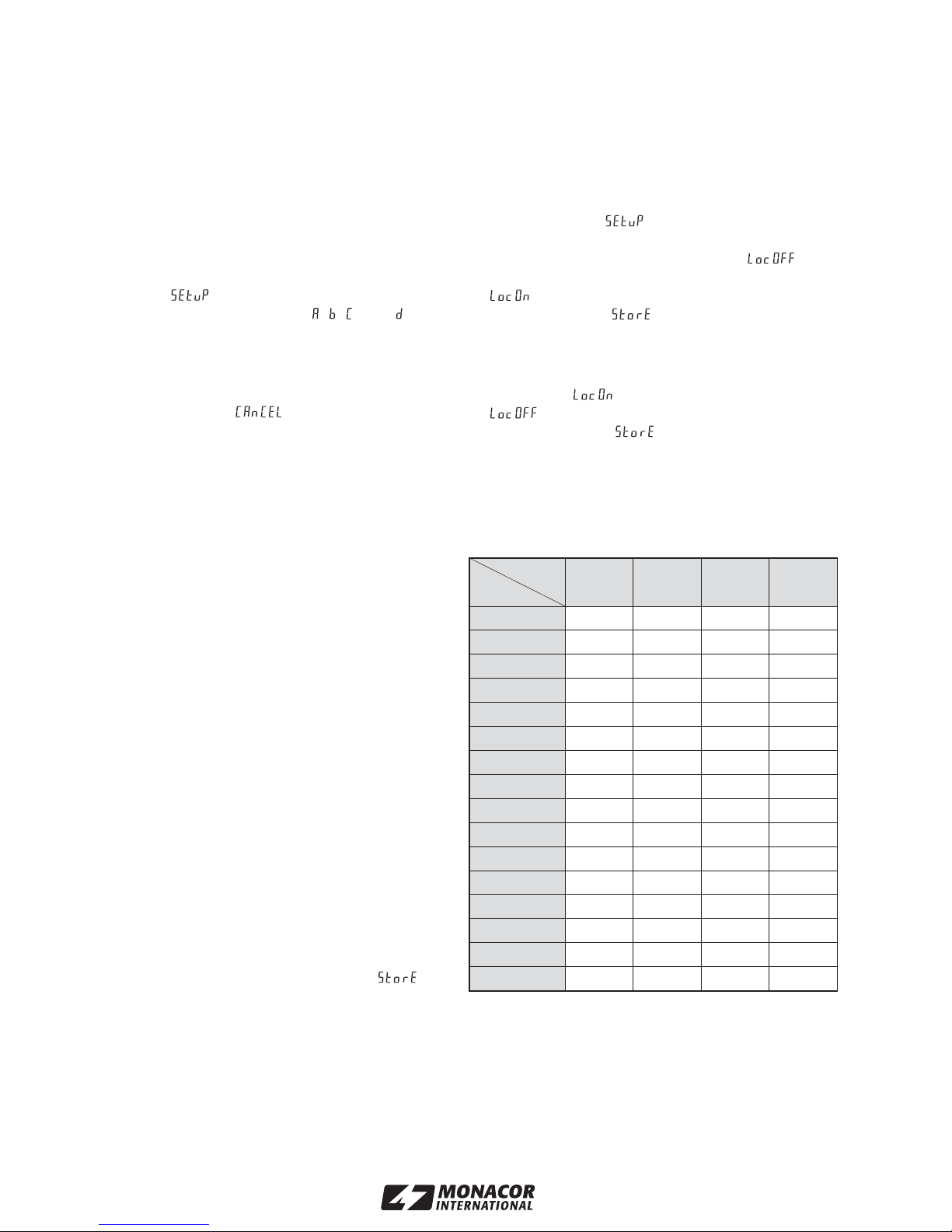
Abb. 4 Empfangsfrequenzen in MHz der Gruppen und Kanäle
Gruppe
Kanal A B C D
1744,250 740,750 741,125 740,625
2745,500 741,375 741,750 741,125
3746,500 743,125 742,625 741,875
4747,125 744,000 743,750 743,625
5748,250 745,250 744,500 745,875
6749,125 746,250 746,125 747,125
7750,500 746,875 746,875 747,875
8753,500 748,000 748,250 749,125
9754,250 748,875 749,000 750,875
10 755,875 750,250 750,875 751,375
11 757,000 753,250 754,500 752,875
12 758,500 754,000 755,875 753,375
13 759,000 755,625 756,625 754,125
14 760,750 756,750 757,750 756,250
15 761,750 758,250 758,375 757,625
16 763,250 763,750 763,750 763,625

8
6.2 Akkumulatoren laden
Die integrierte Schnellladeeinheit ermöglicht das
Laden von zwei Paar NiCd- oder NiMH-Mignon-Akkus
(Typ AA). Vier NiMH-Akkus (1300 mAh) liegen dem
Empfänger bei.
Abb. 5 geöffnetes Akkufach
1) Zum Öffnen des Akkufachs (5) auf das Symbol
drücken. Das Fach rastet aus und lässt sich bis
zum Anschlag herausziehen.
2) Entweder ein oder zwei Akkupaare (a, b), mit den
Plus- und Minuspolen wie in Abb. 5 gezeigt, in das
Fach legen. Die richtige Polarität ist auch vorne auf
dem Akkufach aufgedruckt. Die Akkus so einlegen,
dass der jeweilige Pol des Akkus, der zur Be-
druckung zeigt, mit dem zugehörigen Polaritäts-
symbol ( oder ) übereinstimmt.
Hinweis:
Die Akkus nur paarweise einlegen. Ein
einzelner Akku eines Paares kann nicht aufge-
laden werden.
3) Das Akkufach wieder schließen: Das Fach soweit
hineindrücken, bis es einrastet.
4) Sobald der Empfänger über das Netzgerät an eine
Netzsteckdose angeschlossen ist (Kap. 5), beginnt
der Ladevorgang, auch wenn der Empfänger aus-
geschaltet ist. Optisch wird dieser durch schnelles
Blinken der Ladekontrollanzeigen (4) signalisiert.
Bleibt die zugehörige Kontrollanzeige dunkel,
erfolgt keine Ladung und es ist entweder
kein Akkupaar eingelegt oder
mindestens ein Akku falsch herum eingelegt oder
mindestens ein Akku defekt
Ein dreimaliges, langsames Blinken signalisiert,
dass das Gerät vom Netz getrennt war und die
Stromversorgung wieder hergestellt wurde. Die
Ladeeinheit ist danach betriebsbereit.
5) Nach Abschluss des Ladevorgangs schaltet das
Gerät auf Erhaltungsladung um, die zugehörige
Ladekontrollanzeige leuchtet dann ständig. Die
Akkus sind jetzt voll geladen und können entnom-
men werden.
7 Technische Daten
Gerätetyp: . . . . . . . . . . . . PLL-Multifrequenz-Emp-
fänger mit zwei
Empfangseinheiten und
Diversity-Technik
Funkfrequenzbereich: . . . 740 – 764 MHz,
aufgeteilt in 64 Kanäle
(siehe Tabelle auf Seite 7)
Audiofrequenzbereich: . . . 40 – 18 000 Hz
Klirrfaktor: . . . . . . . . . . . . < 0,6 %
Dynamik: . . . . . . . . . . . . . > 105 dB
Rauschunterdrückung: . . Pilotton-Squelch,
Noise-Mute
Audioausgänge
2 × XLR, sym.: . . . . . . . . 40 mV/150 Ω
1 × 6,3-mm-Klinke, asym.: 250 mV/1 kΩ
Ladeverfahren: . . . . . . . .
-
∆U, 0∆U,
UMAX/Zeitüberwachung
Einsatztemperatur: . . . . . 0 – 40 °C
Stromversorgung: . . . . . . über das beiliegende
Netzgerät an
230 V~/50 Hz
Abmessungen
(ohne Antenne): . . . . . . . . 420 × 50 × 230 mm
Gewicht: . . . . . . . . . . . . . . 2,25 kg
Änderungen vorbehalten.
VORSICHT! Mit der Ladeeinheit dürfen nur NiCd-
oder NiMH-Akkus aufgeladen werden. Nicht wieder-
aufladbare Batterien können beim Versuch, sie auf-
zuladen, auslaufen oder explodieren!
ab
DEUTSCH
Diese Bedienungsanleitung ist urheberrechtlich für MONACOR
®
INTERNATIONAL GmbH & Co. KG geschützt.
Eine Reproduktion für eigene kommerzielle Zwecke – auch auszugsweise – ist untersagt.

9
®

10
All operating elements and connections described
can be found on the fold-out page 3.
1 Operating Elements and Connections
1.1 Front panel
1Operating and indicating field for the receiving unit
CH 1
2Operating and indicating field for the receiving unit
CH 2
3Receiving antennas
4Indications of the charging status, each for the left
and the right pairs of rechargeable batteries in the
battery compartment
does not light up: no batteries are inserted, not cor-
rectly inserted, or the batteries are defective
flashes: the pair of batteries is being charged
lights up continuously: the pair of batteries is fully
charged
5Compartment for the rechargeable batteries to
charge the supplied rechargeable nickel metal
hydride batteries (NiMH) which can be used for the
power supply of the pocket transmitters and wire-
less microphones
6Volume control VOL*
7Key L* for scanning the reception group/channel
in ascending order (in the group adjusting mode/
channel adjusting mode) and for activating the
locking function (in the lock adjusting mode)
8Key M* for scanning the reception group/channel
in descending order (in the group adjusting mode/
channel adjusting mode) and for deactivating the
locking function (in the lock adjusting mode)
9Key SET*
with the unit not locked:
to recall and to exit the adjusting modes for recep-
tion group/channel, locking function
→chapters 6.1, 6.1.1
with the unit locked:
to recall and to exit the adjusting mode for the lock-
ing function →chapter 6.1.1
10 LC multifunction display (fig. 2)
aindication RF* (radio frequency) for the received
power of the radio signal: the longer the bar
graph, the better the reception
bindication AF* (audio frequency) for the volume
of the audio signal received [independent of the
volume controls VOL (6)]: the longer the bar
graph, the higher the volume level
cindication* of the reception group ( , , or )
and of the transmission channel (1 – 16)
The corresponding frequencies are indicated in
the table fig. 4 on page 13.
dreception indications* and : indicate which
of the two antennas receives the more powerful
radio signal
eindication MUTE*: indicates that the correspond-
ing receiving unit is muted because it does not
receive any radio signal or because the radio
signal received is too poor or because the mute
function of the wireless microphone MH-8800G/2
has been switched on
11 POWER switch
12 Mounting brackets for inserting the receiver into a
rack for units →chapter 4
1.2 Rear panel
13 BNC antenna jacks ANT. 1 and ANT. 2 for the two
supplied antennas (3)
14 Outputs AF OUTPUT BAL. (XLR, bal.) for the out-
put signal of the receiving unit CH 1 and the output
signal of the receiving unit CH 2, for connection to
two balanced microphone inputs, e. g. of a mixer or
amplifier
15 Control SQUELCH* for adjusting the threshold for
the noise suppression
16 Output of the master signal of the two receiving
units CH 1 and CH 2 (6.3 mm jack, unbal.) for con-
nection to a line input e. g. of a mixer or amplifier
17 Power supply jack for connection of the supplied
power supply unit
B
A
ENGLISH
*each for the receiving unit CH 1 and the receiving unit CH 2

2 Safety Notes
The units (receiver and power supply unit) correspond
to all required directives of the EU and are therefore
marked with .
Please observe the following items in any case:
GThe units are suitable for indoor use only. Protect
them against dripping water and splash water, high
air humidity, and heat (admissible ambient tempera-
ture range 0 – 40 °C).
GDo not operate the receiver and immediately discon-
nect the power supply unit from the mains
1. in case of visible damage to the units or to the
mains cable,
2. if a defect might have occurred after a unit was
dropped or suffered a similar accident,
3. if malfunctions occur.
In any case the units must be repaired by skilled per-
sonnel.
GA damaged mains cable of the power supply unit
must be replaced by the manufacturer or skilled per-
sonnel only.
GNever pull the mains cable for disconnecting the
mains plug of the power supply unit from the socket,
always seize the plug.
GFor cleaning only use a dry, soft cloth; never use
water or chemicals.
GNo guarantee claims for the units and no liability for
any resulting personal damage or material damage
will be accepted if the units are used for other pur-
poses than originally intended, if they are not cor-
rectly connected, operated, or not repaired in an
expert way.
3 Applications and Accessories
Together with two matching transmitters from JTS, the
dual multifrequency receiver US-903DC PRO/2 makes
up a wireless audio transmission system. The wireless
transmission of music or speech to the audio system
ensures the musicianʼs freedom of movement during
the performance. The transmission range depends on
the local conditions and can reach to a maximum of
100 m.
The receiver operates with “diversity” technique:
The transmission signal is received by two antennas
placed at a distance from each other. The electronic
system selects the signal of the better quality and
passes it on to the inputs of the receiving units.
For the reception four transmission groups (A – D)
with 16 transmission channels each are available,
i. e. altogether 64 factory-set transmission channels.
These channels in the UHF range of 740 – 764 MHz
can be selected as desired.
The unit is supplied with four rechargeable nickel
metal hydride batteries (1300 mAh) which can be used
for power supply of two transmitters and which can be
conveniently charged via the integrated charging unit.
The following transmitters from the product range
of JTS can be used together with the receiver
US-903DC PRO/2:
MH-8800G/2 order no. 25.2950
dynamic hand-held microphone with integrated multi-
frequency transmitter
PT-920BG/2 order no. 25.2960
multifrequency pocket transmitter with Lavalier micro-
phone
To increase the range and the interference immunity,
two antenna amplifiers UB-900/2 (order no. 15.0750)
available as accessories can be used instead of the
antennas supplied. The amplifiers are supplied with
power via the antenna jacks of the receiver.
When using several receivers in the audio system, the
antenna splitter UA-900 (order no. 15.0610) can be
used. It will also supply the power for a maximum of
four receivers.
4 Rack Mounting
The US-903DC PRO/2 is provided as a table top unit
or for installation into a rack for units with a width of
482 mm (19"). For the rack installation unscrew the
four feet and screw the two supplied mounting brack-
ets (12) with two screws each to the front at the left
and right sides of the housing.
WARNING The power supply unit is supplied with
hazardous mains voltage (230 V~).
Leave servicing to skilled personnel
only. Inexpert handling may cause an
electric shock hazard.
If the units are to be put out of operation de-
finitively, take them to a local recycling plant
for a disposal which is not harmful to the envi-
ronment.
Defective rechargeable batteries do not belong in the
household rubbish; always take them to a special
waste disposal (e. g. collecting container at your
retailer).
11
ENGLISH
®

12
5 Connection
1) Insert the two supplied antennas (3) to the BNC
antenna jacks ANT. 1 and ANT. 2 (13) and place
them in a vertical position.
2) For connection to the subsequent unit (e. g. mixer,
amplifier) the following audio outputs can be used:
AF OUTPUT BAL. (14)
balanced XLR outputs for the output signals of
the receiving units CH 1 and CH 2 for connection
to a balanced microphone input each
AF MIXED OUTPUT UNBAL. (16)
unbalanced 6.3 mm output for the master signal
of the two receiving units for connection to a line
input (a matching connection cable is supplied)
3) Connect the supplied power supply unit to the jack
(17) for the power supply and the mains plug of the
power supply unit to a socket (230 V~/50 Hz).
6 Operation
Switch on the receiver with the POWER switch (11).
The display (10) shows the adjusted reception group
and the adjusted transmission channel (c) each for the
two receiving units. If one receiving unit does not
receive a radio signal of sufficient power or if the mute
function of the wireless microphone MH-8800G/2 is
switched on, the receiving unit is muted and the dis-
play shows MUTE (e).
Make the following adjustments separately for each
receiving unit.
1) Before switching on the transmitter, set the receiv-
ing unit to a transmission channel which is not used
and which is free from interference, see chapter
6.1. Via the audio unit connected to the output, no
interference or signals of other transmissions must
be audible and the reception bar graph RF (a) must
not indicate any signal.
2) Switch on the wireless microphone MH-8800G/2 or
the pocket transmitter PT-920BG/2 and set it to the
same transmission group and the same transmis-
sion channel adjusted on the receiver: see instruc-
tion manual of the microphone or the transmitter.
If the transmitter and the receiver are set to the
same channel and if a radio signal of sufficient
power is received, the muting will be deactivated
[indication MUTE (e) is extinguished]. One of the
indications or (d) will light up to indicate which
of the two antennas receives the more powerful
radio signal. The bar graph RF (a) shows the re-
ceiving quality: the more segments of the bar graph
light up, the better the reception.
If the reception is poor or interfered, check if
a the reception is better on another transmission
channel.
b the batteries of the transmitter are not suffi-
ciently charged any more (see battery status
indication on the transmitter).
c the distance between the transmitter and the
receiver is too long.
d the reception is disturbed by objects in the trans-
mission path.
The transmitter and the receiver should have a
minimum distance of 50 cm to metal objects and
any sources of interference, e. g. motors or fluo-
rescent tubes.
e the reception can be improved by turning the
antennas.
f the squelch has been adjusted too high with the
control SQUELCH (15) [see operating step 5].
3) Speak/sing into the microphone. The volume level
of the audio signal received is displayed via the bar
graph AF (b): The more segments of the bar graph
AF light up, the higher the volume level.
Adjust the wireless microphone or the pocket
transmitter to an optimum volume via the indication
AF: see instruction manual of the microphone or
the transmitter.
4) Match the output level of the receiving unit by
means of the volume control VOL (6) to the input of
the subsequent unit.
5) With the control SQUELCH (15) adjust the thresh-
old value for the response of the squelch. The fur-
ther the control is turned clockwise, the higher is
the threshold value.
The squelch will mute the receiving unit if during
music intervals high-frequency interference signals
are received of which the level is below the thresh-
old value adjusted. With a higher threshold value,
however, the operating range of the wireless sys-
tem will also be reduced as the receiving unit will
also be muted if the power of the radio signal of the
microphone falls below the threshold value
adjusted. Thus, a higher threshold value may be
adjusted with the control SQUELCH if the reception
of the microphone signal is good. However, with a
longer distance between the transmitter and re-
ceiver a lower value should be selected.
6) After operation, switch off the receiver with the
POWER switch (11). Remember to switch off the
wireless microphones/pocket transmitters as well,
otherwise the batteries will be exhausted the next
time the system is used.
If the receiver is not used for a longer period,
disconnect the power supply unit from the mains as
it will have a low power consumption even with the
receiver switched off.
Note:
Switching off the unit does not affect the inte-
grated charging unit (chapter 6.2). The charging
process will not be interrupted before the mains
plug is disconnected.
B
A
ENGLISH

6.1 Adjusting the reception group
and the transmission channel
1) Keep the key SET (9) pressed for 2 s until the dis-
play shortly indicates . Then the reception
group adjusted ( , , or ) flashes above the letter-
ing GROUP (c) and thus indicates the activated
group adjusting mode.
Note:
To exit the adjusting mode without making an
adjustment, press the key SET so many times
until the display shows . Then the unit will
return to normal operation.
2) As long as the reception group flashes in the dis-
play, it is possible to adjust it: With the key L(7) the
groups will be scanned in ascending order, with the
key M(8) they will be scanned in descending order.
The corresponding channels and transmission fre-
quencies can be found in the table in fig. 4.
Note:
If other wireless transmission systems are
operated with this wireless system at the same
time, the radio frequencies of the individual sys-
tems should be carefully matched to each other
to prevent interference.
3) Confirm the input with the key SET. The present
transmission channel now flashes above the let-
tering CHANNEL (c) in the display, the channel ad-
justing mode is active.
4) Use the cursor keys to adjust the transmission
channel (1 – 16): With the key Mthe channels will
be scanned in descending order, with the key Lin
ascending order.
Note:
It is not possible to set both receiving units to
the same channel. The channel selected for one
receiving unit will be automatically skipped dur-
ing channel adjustment for the other receiving
unit.
5) To memorize the adjustments for the reception
group and the transmission channel, press the key
SET. The display will shortly indicate , the
adjusting mode will be exited, and the unit will go to
normal operation.
6.1.1 Lock mode
(locking the channel selecting keys)
To prevent accidental change of the transmission
channels selected, it is possible to activate the lock
mode. With the lock mode activated, it is not possible
any more to call the reception group mode/channel
adjusting mode for both receiving units.
1) To activate the lock mode, keep the key SET (9) in
one of the operating panel pressed for 2 s until the
display shortly indicates . Then the reception
group adjusted will flash. Press the key SET two
more times until will flash in the display.
Press the key L(7) so that will flash in the
display now. Then press the key SET. is
shortly displayed before the unit will go to normal
operation.
2) To deactivate the lock mode, keep the key SET in
one of the operating panel pressed for 2 s until
flashes in the display. With the key M(8)
switch to and confirm with the key SET.
will shortly be displayed, the unit allows op-
eration of the keys without limitation.
Note:
The lock mode will not be deactivated by switch-
ing off the receiver. After switching on, the channel se-
lection will continue to be locked.
13
ENGLISH
®
Fig. 4 Receiving frequencies in MHz of the groups and channels
Group
Channel
A B C D
1744.250 740.750 741.125 740.625
2745.500 741.375 741.750 741.125
3746.500 743.125 742.625 741.875
4747.125 744.000 743.750 743.625
5748.250 745.250 744.500 745.875
6749.125 746.250 746.125 747.125
7750.500 746.875 746.875 747.875
8753.500 748.000 748.250 749.125
9754.250 748.875 749.000 750.875
10 755.875 750.250 750.875 751.375
11 757.000 753.250 754.500 752.875
12 758.500 754.000 755.875 753.375
13 759.000 755.625 756.625 754.125
14 760.750 756.750 757.750 756.250
15 761.750 758.250 758.375 757.625
16 763.250 763.750 763.750 763.625

14
6.2 Recharging the rechargeable batteries
The integrated quick charging unit allows charging of
two pairs of NiCd or NiMH rechargeable batteries
of size AA. Four NiMH rechargeable batteries
(1300 mAh) are supplied with the receiver.
Fig. 5 Open compartment of the rechargeable batteries
1) To open the compartment (5) for the rechargeable
batteries, press the symbol . The compartment
disengages and can be pulled out up to the stop.
2) Either insert one or two pairs of rechargeable batter-
ies (a, b) into the compartment, with the positive and
negative poles as shown in fig. 5. The correct polar-
ity is also printed on the front of the compartment.
Insert the rechargeable batteries so that the respec-
tive pole of the battery showing to the imprint corre-
sponds to the respective polarity symbol ( or ).
Note:
Only insert the rechargeable batteries in
pairs. A single rechargeable battery of a pair
cannot be recharged.
3) Close the compartment again: Press the compart-
ment so far until it locks into place.
4) As soon as the receiver is connected to a mains
socket via the power supply unit (chapter 5), the
charging process will start, even with the receiver
switched off. This is shown by a fast flashing of the
indications of the charging status (4).
If the corresponding indication of the charging
status remains dark, no charging will be made.
Either no pair of rechargeable batteries has been
inserted, or
at least one rechargeable battery has been inserted
the wrong way round, or
at least one rechargeable battery is defective.
A slow flashing of three times indicates that the
unit was disconnected from the mains and the
power supply has been reestablished. Then the
charging unit is ready for operation again.
5) After the charging process is finished, the unit will
switch to trickle charging, the corresponding indica-
tion of the charging status will light up continuously.
The rechargeable batteries are fully charged now
and can be taken out.
7 Specifications
Type of unit: . . . . . . . . . . . PLL multifrequency re-
ceiver with two receiving
units and diversity tech-
nique
Radio frequency range: . . 740 – 764 MHz,
divided into 64 channels
(see table page 13)
Audio frequency range: . . 40 – 18 000 Hz
THD: . . . . . . . . . . . . . . . . < 0.6 %
Dynamic range: . . . . . . . . > 105 dB
Noise suppression: . . . . . pilot tone squelch,
noise mute
Audio outputs
2 × XLR, bal.: . . . . . . . . 40 mV/150 Ω
1 × 6.3 mm jack, unbal.: 250 mV/1 kΩ
Charging process: . . . . . .
-
∆U, 0∆U,
UMAX/time supervision
Ambient temperature: . . . 0 – 40 °C
Power supply: . . . . . . . . . via the supplied PSU con-
nected to 230 V~/50 Hz
Dimensions
(w/o antennas): . . . . . . . . 420 × 50 × 230 mm
Weight: . . . . . . . . . . . . . . . 2.25 kg
Subject to technical modification.
ab
CAUTION! With the charging unit only NiCd or NiMH
rechargeable batteries must be charged. If attempts
are made to charge non-rechargeable batteries, they
can leak or explode!
ENGLISH
All rights reserved by MONACOR
®
INTERNATIONAL GmbH & Co. KG. No part of this instruction manual may
be reproduced in any form or by any means for any commercial use.

15
®

16
Vous trouverez sur la page 3, dépliable, les élé-
ments et branchements décrits.
1 Eléments et branchements
1.1 Face avant
1Zone dʼutilisation et dʼaffichage pour lʼunité de
réception CH 1
2Zone dʼutilisation et dʼaffichage pour lʼunité de
réception CH 2
3Antennes de réception
4LEDs de contrôle de charge respectivement pour
la paire dʼaccumulateurs gauche et droite dans le
compartiment batterie
ne brille pas : aucun accumulateur inséré, accumu-
lateurs mal positionnés ou défectueux
clignote : la paire dʼaccumulateurs est chargée
brille en continu : la paire dʼaccumulateurs est en-
tièrement chargée
5Compartiment accumulateur pour charger les
accumulateurs Nickel Métal hybride (NiMH) livrés,
pouvant être utilisés pour alimenter les émetteurs
de poche et microphones sans fil
6Potentiomètre de réglage de volume VOL*
7Touche L* pour la recherche en ordre croissant du
groupe de réception/canal (en mode réglage de
groupe/de canal) et pour activer la fonction ver-
rouillage (en mode réglage verrouillage)
8Touche M* pour la recherche en ordre décroissant
du groupe de réception/canal (en mode réglage de
groupe/de canal) et pour désactiver la fonction
verrouillage (en mode réglage verrouillage)
9Touche SET*
si lʼappareil nʼest pas verrouillé :
pour appeler et quitter les modes de réglage pour
le groupe de réception/canal, fonction verrouillage,
voir chapitre 6.1, 6.1.1
si lʼappareil est verrouillé :
pour appeler et quitter le mode de réglage pour la
fonction verrouillage, voir chapitre 6.1.1
10 Ecran LCD multifonctions (schéma 2)
aaffichage RF* (radio frequency) pour la puis-
sance de réception du signal radio : plus le
nombre de segments affiché est grand,
meilleure est la réception.
baffichage AF* (audio frequency) pour le volume
du signal audio reçu [indépendant des réglages
de volume VOL (6)] : plus le nombre de seg-
ments affiché est grand, plus le niveau de
volume est élevé.
cAffichage* du groupe de réception ( , , ou )
et du canal de transmission (1 – 16).
Les fréquences correspondantes sont indiquées
dans le tableau schéma 4, page 19.
dAffichages de réception* et : indiquent
quelle antenne sur les deux reçoit le signal radio
le plus fort
eAffichage MUTE* : indique que lʼunité de récep-
tion correspondante est muette : aucun signal
radio ou un signal radio trop faible est reçu ou la
fonction Mute a été activée sur le micro sans fil
MH-8800G/2.
11 Interrupteur Marche/Arrêt
12 Etriers de montage pour placer le récepteur dans
un rack, voir chapitre 4.
1.2 Face arrière
13 Prises dʼantenne BNC ANT. 1 et ANT. 2 pour les
deux antennes livrées (3)
14 Sorties AF OUTPUT BAL. (XLR, sym.) pour le si-
gnal de sortie de lʼunité de réception CH 1 et le si-
gnal de sortie de lʼunité de réception CH 2, pour
relier à deux entrées micro symétriques par
exemple dʼune table de mixage ou dʼun amplifica-
teur.
15 Potentiomètres de réglage SQUELCH* pour régler
le seuil de déclenchement pour lʼélimination des
interférences.
16 Sortie du signal master des deux unités de récep-
tion CH 1 et CH 2 (prise jack 6,35 femelle, asym.),
pour relier à une entrée ligne par exemple dʼune
table de mixage ou dʼun amplificateur
17 Prise alimentation pour brancher le bloc secteur
livré
A
B
FRANÇAIS
*respectivement pour lʼunité de réception CH 1 et pour lʼunité
de réception CH 2

2 Conseils dʼutilisation et de sécurité
Les appareils (récepteur et le bloc secteur) répondent
à toutes les directives nécessaires de lʼUnion Euro-
péenne et portent donc le symbole .
Respectez scrupuleusement les points suivants :
GLes appareils ne sont conçus que pour une utilisa-
tion en intérieur. Protégez-les de tout type de pro-
jections dʼeau, des éclaboussures, dʼune humidité
élevée et de la chaleur (plage de température de
fonctionnement autorisée : 0 – 40 °C).
GNe faites pas fonctionner le récepteur et débranchez
immédiatement le bloc secteur lorsque :
1. les appareils ou le cordon secteur présentent des
dommages visibles
2. après une chute ou accident similaire, lʼappareil
peut présenter un défaut.
3. des dysfonctionnements apparaissent.
Dans tous les cas, faites appel à un technicien spé-
cialisé pour effectuer les réparations.
GTout cordon secteur endommagé du bloc secteur ne
doit être remplacé que par le fabricant ou un techni-
cien habilité.
GNe débranchez jamais le bloc secteur en tirant sur le
cordon secteur, tenez-le toujours par la prise.
GPour le nettoyage utilisez uniquement un chiffon sec
et doux, en aucun cas de produit chimique ou dʼeau.
GNous déclinons toute responsabilité en cas de dom-
mages matériels ou corporels résultants si les appa-
reils (le récepteur ou le bloc secteur) sont utilisés
dans un but autre que celui pour lequel ils ont été
conçus, sʼils ne sont pas correctement branchés,
utilisés ou réparés par un technicien habilité ; en
outre, la garantie deviendrait caduque.
3 Possibilités dʼutilisation et accessoires
Le récepteur multifréquences 2 canaux US-903DC
PRO/2 constitue, combiné à deux émetteurs JTS, un
système de transmission audio sans fil. Via la trans-
mission sans fil de la musique ou des paroles vers
lʼinstallation audio, le musicien conserve toute sa
liberté de mouvement pendant ses déplacements. La
portée de transmission dépend de la configuration des
lieux dʼutilisation et peut atteindre 100 m.
Le récepteur fonctionne avec la technologie “Diver-
sity” : le signal dʼémission est reçu par deux antennes
positionnées à deux endroits distincts. Un circuit élec-
tronique sélectionne le signal ayant la meilleure qualité
et le dirige vers les entrées des unités de réception.
Pour la réception, quatre groupes dʼémetteur (A à
D) avec respectivement 16 canaux de transmission
soit en tout 64 canaux de transmission réglés en usine
sont disponibles. Ces canaux peuvent être librement
choisis dans la plage UHF 740 – 764 MHz.
Quatre accumulateurs Nickel-Métal hybride (NiMH)
[1300 mAh], pouvant être utilisés pour alimenter deux
émetteurs et pouvant être chargés via lʼunité de
charge intégrée sont également livrés.
Les émetteurs suivants, dans la gamme JTS peuvent
être utilisés avec le US-903DC PRO/2 :
MH-8800G/2 (ref. num. : 25.2950) :
microphone main dynamique avec émetteur multifré-
quences intégré
PT-920BG/2 (ref. num. : 25.2960) :
émetteur de poche multifréquences avec microphone
cravate
Pour augmenter la portée et la sécurité par rapport
aux interférences, on peut utiliser, à la place de la
paire dʼantennes livrées, deux amplificateurs dʼan-
tennes, UB-900/2 (ref. num. 15.0750) disponibles en
option. Les amplificateurs reçoivent leur alimentation
via les prises dʼantenne du récepteur.
Si vous utilisez plusieurs récepteurs dans lʼinstallation
audio, on peut insérer le répartiteur dʼʼantenne UA-900
(ref. num. 15.0610). Il délivre également lʼalimentation
pour quatre récepteurs au plus.
4 Montage en rack
Le récepteur est prévu pour être posé directement sur
une table ou placé dans un rack pour appareils au
standard 19"/482 mm. Pour une installation en rack,
dévissez les quatre pieds, et vissez les deux étriers de
montage livrés (12) avec respectivement deux vis à
lʼavant sur le côté droit et le côté gauche du boîtier.
AVERTISSEMENT Le bloc secteur est alimenté par
une tension 230 V~, dangereuse.
Ne touchez jamais lʼintérieur de
lʼappareil car vous pourriez subir
une décharge électrique.
Lorsque les appareils sont définitivement reti-
rés du marché, vous devez les déposer dans
une usine de recyclage de proximité pour
contribuer à leur élimination non polluante.
Ne jetez pas les accumulateurs défectueux ou les
batteries usagées dans la poubelle domestique.
Déposez-les dans un container spécifique ou rappor-
tez-les à votre revendeur.
17
FRANÇAIS
®

18
5 Branchement
1) Placez les deux antennes livrées (3) dans les
prises dʼantenne BNC ANT. 1 et ANT. 2 (13) et met-
tez-les à la verticale.
2) Pour brancher lʼappareil suivant (par exemple table
de mixage, amplificateur), les sorties audio sui-
vantes peuvent être utilisées :
AF OUTPUT BAL. (14) :
sorties XLR symétriques pour les signaux de
sortie des unités de réception CH 1 et CH 2 pour
brancher respectivement à une entrée micro
symétrique
AF MIXED OUTPUT UNBAL. (16) :
sortie prise jack 6,35 asymétrique pour le signal
master des deux unités de réception, pour bran-
cher à une entrée ligne (cordon de branchement
correspondant livré).
3) Reliez le bloc secteur livré à la prise (17) pour lʼali-
mentation puis reliez la fiche du bloc secteur à une
prise secteur 230 V~/50 Hz.
6 Utilisation
Allumez le récepteur avec la touche POWER (11).
Lʼaffichage (10) indique pour les deux unités de récep-
tion, respectivement le groupe de réception réglé et le
canal de transmission réglé (c). Tant quʼune unité de
réception ne reçoit pas de signal radio suffisamment
puissant ou si sur le microphone sans fil MH-8800G/2
la fonction Mute est allumée, lʼunité de réception reste
muette et lʼaffichage indique MUTE (e).
Effectuez les réglages suivants pour chaque unité de
réception séparément.
1) Laissez lʼémetteur encore éteint. Réglez tout
dʼabord lʼunité de réception sur un canal de trans-
mission libre et sans interférences, voir chapitre
6.1. Via lʼappareil audio relié à la sortie, il ne faut
pas entendre de perturbations ou signaux dʼautres
transmissions et la LED de réception RF (a) ne doit
pas afficher de signal.
2) Allumez le microphone sans fil MH-8800G/2 ou
lʼémetteur de poche PT-920BG/2 et réglez-les sur
le même groupe dʼémetteurs et le même canal de
transmission que sur le récepteur : voir notice du
microphone ou de lʼémetteur.
Si le même canal de transmission est réglé sur
lʼémetteur et le récepteur, et si la réception du si-
gnal radio est suffisamment forte, la coupure du
son est désactivée [affichage MUTE (e) éteint]. Un
des affichages ou (d) brille et indique ainsi
laquelle des deux antennes reçoit le signal radio le
plus puissant. Lʼaffichage RF (a) indique la qualité
de réception : plus le nombre de segments affichés
est grand, meilleure est la réception.
Si la réception est mauvaise, ou perturbée, vérifiez
les points suivants :
a la réception est meilleure avec un autre canal de
transmission.
b les batteries de lʼémetteur ne sont plus assez
chargées (voir affichage de lʼétat des batteries
sur lʼémetteur).
c la distance entre lʼémetteur et le récepteur est
trop grande.
d la réception est gênée par des objets dans la
zone de transmission.
Les émetteurs et récepteurs devraient être à
une distance minimale de 50 cm des objets
métalliques et sources possibles dʼinterfé-
rences, p. ex. moteurs électriques, tubes néon.
e la réception peut être améliorée en tournant les
antennes.
f le seuil de déclenchement réglé avec le réglage
SQUELCH (15) est trop haut (voir point 5).
3) Parlez ou chantez dans le micro sans fil. Le niveau
de volume du signal audio reçu est restitué via lʼaf-
fichage AF (b) : plus le nombre de segments du
bargraphe AF affichés est grand, plus le volume est
élevé.
Réglez le microphone sans fil ou lʼémetteur de
poche sur le volume optimal en fonction des indica-
tions du bargraphe AF : voir notice dʼutilisation du
microphone ou de lʼémetteur.
4) Avec le réglage de volume VOL (6), adaptez le
niveau de sortie de lʼunité de réception à lʼentrée de
lʼappareil suivant.
5) Avec le réglage SQUELCH (15), réglez le seuil de
déclenchement pour lequel lʼélimination des inter-
férences doit réagir. Plus le réglage est tourné dans
le sens des aiguilles dʼune montre, plus la valeur du
seuil est grande.
Lʼélimination des interférences coupe le son de
lʼunité de réception si dans des pauses musicales,
des signaux perturbateurs haute fréquence sont
reçus, dont les niveaux sont sous le seuil réglé.
Avec un seuil plus élevé, la portée du système sans
fil se réduit cependant puisque lʼunité de réception
est également coupée lorsque la puissance du si-
gnal radio du micro baisse sous le seuil réglé. Ainsi
lors dʼune bonne réception du signal micro, un seuil
plus élevé peut être réglé avec le réglage
SQUELCH ; en revanche, une valeur plus basse
devrait être réglée si la distance entre lʼémetteur et
le récepteur est plus grande.
6) Après toute utilisation, éteignez le récepteur avec
lʼinterrupteur POWER (11). Nʼoubliez pas dʼéteindre
également les microphones sans fil/émetteurs de
poche, sinon, lors de la prochaine utilisation, les
batteries seront mortes.
B
A
FRANÇAIS

En cas de non utilisation prolongée du récep-
teur, débranchez le bloc secteur du courant car,
même si le récepteur est éteint, le bloc secteur a
une faible consommation.
Remarque :
Eteindre lʼappareil nʼa pas dʼinfluence
sur lʼunité de charge intégrée (chapitre 6.2). Le
processus de charge nʼest interrompu que lors-
quʼon retire le cordon secteur de la prise secteur.
6.1 Réglage du groupe de réception
et du canal de transmission
1) Maintenez la touche SET (9) enfoncée deux
secondes jusquʼà ce que lʼaffichage indique briève-
ment . Le groupe de réception réglé ( , , ou
) clignote au-dessus de lʼinscription GROUP (c) et
indique que le mode de réglage de groupe est
activé.
Remarque :
Pour quitter le mode de réglage sans
effectuer de réglage, appuyez sur la touche SET
jusquʼà ce que sʼaffiche. Lʼappareil
revient alors au mode normal.
2) Tant que le groupe de réception clignote sur lʼaffi-
chage, le groupe peut être sélectionné : avec la
touche L(7), les groupes défilent en ordre crois-
sant, avec la touche M(8), en ordre décroissant.
Les canaux et les fréquences dʼémission corres-
pondants sont indiqués sur le tableau, schéma 4.
Remarque :
Si dʼautres systèmes de transmission
sans fil doivent fonctionner en même temps que
ce système, veillez à ce que les fréquences de
chaque système soient déterminées avec préci-
sion pour éviter toute interférence.
3) Avec la touche SET, confirmez la saisie. Sur lʼaffi-
chage, le canal de transmission actuel clignote au-
dessus de lʼinscription CHANNEL (c), le mode de
réglage de canal est actif.
4) Avec les touches flèche, réglez le canal de trans-
mission (1 à 16) : avec la touche M, les canaux défi-
lent en ordre décroissant, avec la touche L, en
ordre croissant.
Remarque :
les deux unités de réception ne peu-
vent pas être réglées sur le même canal ; le
canal sélectionné pour une unité de réception
est automatiquement sauté lors du réglage du
canal de lʼautre unité de réception.
5) Mémorisez les réglages du groupe de réception et
du canal de transmission en appuyant sur la touche
SET. Sur lʼaffichage sʼaffiche brièvement, on
quitte le mode de réglage, lʼappareil revient à un
fonctionnement normal.
6.1.1 Mode verrouillage (verrouillage des touches
de sélection de canaux)
Pour éviter que les canaux de transmission sélection-
nés ne soient déréglés par inadvertance, le mode ver-
rouillage peut être activé. Dans ce cas, pour les deux
unités de réception, le mode de groupe de
réception / de réglage des canaux ne peut plus être
appelé.
1) Pour activer le mode verrouillage, maintenez la
touche SET (9) enfoncée 2 secondes dans une des
zones dʼutilisation jusquʼà ce que sur lʼaffichage
sʼaffiche brièvement. Ensuite le groupe de
réception réglé clignote. Appuyez encore deux fois
sur la touche SET jusquʼà ce que sur lʼaffichage
clignote. Appuyez sur la touche L(7) jusquʼ à
ce que clignote. Appuyez ensuite sur la
touche SET. sʼaffiche brièvement, puis lʼap-
pareil revient au fonctionnement normal.
2) Pour désactiver le mode verrouillage, maintenez
la touche SET enfoncée deux secondes dans une
des zones dʼutilisation jusquʼà ce que cli-
gnote. Avec la touche M(8), commutez sur
et confirmez avec la touche SET. sʼaffiche
brièvement, lʼappareil peut désormais être utilisé
via ses touches sans aucune limitation.
Remarque :
le mode verrouillage nʼest pas désactivé
lorsquʼon éteint le récepteur. Une fois rallumé, la
sélection des canaux est encore verrouillée.
19
®
Schéma 4 Fréquences de réception en MHz des groupes et
canaux
FRANÇAIS
Groupe
Canal A B C D
1744,250 740,750 741,125 740,625
2745,500 741,375 741,750 741,125
3746,500 743,125 742,625 741,875
4747,125 744,000 743,750 743,625
5748,250 745,250 744,500 745,875
6749,125 746,250 746,125 747,125
7750,500 746,875 746,875 747,875
8753,500 748,000 748,250 749,125
9754,250 748,875 749,000 750,875
10 755,875 750,250 750,875 751,375
11 757,000 753,250 754,500 752,875
12 758,500 754,000 755,875 753,375
13 759,000 755,625 756,625 754,125
14 760,750 756,750 757,750 756,250
15 761,750 758,250 758,375 757,625
16 763,250 763,750 763,750 763,625

20
6.2 Charge des accumulateurs
Lʼunité de charge rapide intégrée permet de charger
deux paires dʼaccumulateurs NiCd ou NiMH de type
R6. Quatre accumulateurs NiMH (1300 mAh) sont
livrés avec le récepteur.
Schéma 5 Compartiment accumulateur ouvert
1) Pour ouvrir le compartiment accumulateur (5),
appuyez sur le symbole . Le compartiment se
désenclenche et peut être tiré jusquʼà la butée.
2) Insérez dans le compartiment comme indiqué sur
le schéma 5, une ou deux paires dʼaccumulateurs
(a, b) en respectant les pôles plus et moins. La
polarité correcte est indiquée dans le compartiment
à lʼavant. Placez les accumulateurs de telle sorte
que le pôle respectif de lʼaccumulateur montrant le
repère corresponde avec le symbole de polarité
correspondant ( ou ).
Remarque :
Insérez les accumulateurs uniquement
par paire. Un accumulateur seul dans une paire
ne peut pas être chargé.
3) Refermez le compartiment : repoussez le comparti-
ment jusquʼà ce quʼil sʼenclenche.
4) Dès que le récepteur est relié à une prise secteur
via le bloc secteur (chapitre 5), le processus de
charge débute, même si le récepteur est éteint. Il
est indiqué par un clignotement rapide des LEDs
de contrôle de charge (4).
Si la LED de contrôle correspondante reste
sombre, il nʼy a pas de charge :
aucune paire dʼaccumulateurs nʼest insérée ou
un accumulateur au moins est mal positionné ou
un accumulateur au moins est défectueux.
Un clignotement lent trois fois indique que lʼap-
pareil a été débranché du secteur et que lʼalimenta-
tion a été rétablie. Lʼunité de charge est ensuite
prête à fonctionner.
5) Une fois le processus de charge terminé, lʼappareil
revient à une charge de maintien, la LED de
contrôle de charge correspondante brille en
continu. Les accumulateurs sont entièrement char-
gés et peuvent être retirés.
7 Caractéristiques techniques
Type dʼappareil : . . . . . . . récepteur PLL multifré-
quences avec deux unités
de réception, technologie
Diversity
Bande de fréquences
radio : . . . . . . . . . . . . . . . . 740 – 764 MHz,
divisée en 64 canaux
(voir tableau page 19)
Bande de fréquences
audio : . . . . . . . . . . . . . . . 40 – 18 000 Hz
Taux de distorsion : . . . . . < 0,6 %
Dynamique : . . . . . . . . . . > 105 dB
Elimination interférences : squelch signal pilote,
Noise Mute
Sorties audio
2 × XLR, sym. : . . . . . . . 40 mV/150 Ω
1 × jack 6,35, asym. : . . 250 mV/1 kΩ
Processus de charge : . . .
-
∆U, 0∆U,
UMAX/surveillance temps
Température de
fonctionnement : . . . . . . . 0 – 40 °C
Alimentation : . . . . . . . . . . via le bloc secteur livré
branché à 230 V~/50 Hz
Dimensions
(sans antennes) : . . . . . . . 420 × 50 × 230 mm
Poids : . . . . . . . . . . . . . . . 2,25 kg
Tout droit de modification réservé.
PRECAUTION ! Seuls des accumulateurs NiCd ou
NiMH ne peuvent être chargés avec cette station de
charge. Des batteries non rechargeables pourraient
couler ou exploser si on tentait de les charger.
ab
FRANÇAIS
Notice dʼutilisation protégée par le copyright de MONACOR
®
INTERNATIONAL GmbH & Co. KG. Toute repro-
duction même partielle à des fins commerciales est interdite.
Table of contents
Languages:
Other JTS Receiver manuals