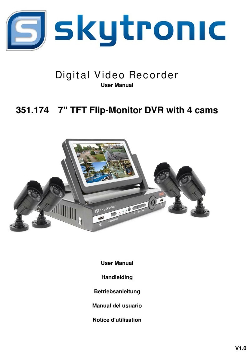
SKYTRONIC 351.174 User manual

Digital Video Recorder
User Manual
351.174 7" TFT Flip-Monitor DVR with 4 cams
User Manual
Handleiding
Betriebsanleitung
V1.1

1 - OPERATING PRECAUTIONS
• Do not install the video surveillance kit in locations with extreme humidity and/or temperatures, or where there is a risk the
equipment might rust or be exposed to dust. Do not install the video surveillance kit in cold locations or locations subject to
large
temperature fluctuations.
• he cameras must not be exposed to direct sunlight. Preferred locations are porches or covered areas.
• he cameras must not be installed in locations where the lens filter might be vulnerable to scratching or dirt.
• Never obstruct the monitor's ventilation holes.
• Do not daisy chain extension cords and/or multi-socket adapters.
• Do not install near acidic chemicals, ammonia or sources of toxic gasses.
• Do not install in explosive environments or near volatile or inflammable products.
• Never put objects containing water on top of the device.
• Never cover the device.
• he video surveillance kit monitor and mains adapter must only be used indoors.
• Make sure that the device and power supply are well ventilated.
• Do not place the device or cameras near magnetic sources.
2 - MAINTENANCE AND CLEANING
• Always unplug the products from the mains before carrying out any maintenance.
• Never use abrasive or corrosive substances to clean the product.
• Use a soft, clean cloth or special LCD screen wipes.
• Never spray anything onto the product as it may damage the internal workings.
3 – RECYCLING Disposing of used batteries in the household waste is strictly forbidden. Batteries/accumulators containing
harmful substances are marked with symbols (shown opposite) which indicate that it is forbidden to discard them in the
household waste. he corresponding heavy metal designations are as follows: Cd = cadmium, Hg = mercury, Pb = lead. You
can dispose of these batteries/accumulators at local recycling amenities (centres for sorting recyclable materials) which are
required to accept them. Keep batteries/button cells/accumulators out of reach of children and store them in a safe place not
accessible to them as they could be swallowed by children or domestic animals. May be fatal if swallowed. In the event that a
battery is swallowed, consult a doctor or go to A&E immediately. Never short-circuit the batteries, and do not burn or recharge
them. as there is a danger they might explode.
his logo denotes that devices which are no longer used must not be disposed of as household waste. as they are
likely to contain hazardous substances which are dangerous to health and the environment. ake these devices back
to your dealer or use your council's selective recycling facilities.
Thanks for b ying o r digital video recorder
Safety Preca tions:
o avoid risks and possible loss of property, please be sure to follow the right operations
printed in the manual
Please place and use the product under the environment 0℃-55℃,avoid place it in humid
environment
Avoid direct sunlight or heat sources
Avoid humid ,dusty or smoky environment
Keep the device in horizontal installation condition
Installing it in stable sites, avoid downfall
Please don’t place other devices on the DVR
Install DVR in well-ventilated sites, avoid blocking the vents
Use it under rated input and output range
Please don’t disassemble the DVR at will
Installation
1.1Open Package Check
First, please check whether any visible damage to the package appearance. he protective materials used for the package of
the DVR can protect most accidental clashes during transportation.
hen, checking if all accessories are equipped
1.2Connection Diagram
Declaration:
Incorrect description of technology and printing may be incl ded in this man al, we’ll pdate it
irreg larly witho t prior notice; pdated contents will be printed in new version. we’ll keep on
improve the program or pdate the description of man al. if any inconformity, please in kind
prevail!

1.3Back Panel Instr ctions
Instr ction: Different models with different functions, please in kind prevail, details please refer to following table.
Identification Name Description
Video in Video input 1-4CH multi-channel video input(BNC)
Audio in Audio Input 1CH multi-channel audio input(RCA)
Video out Video output Video output
Audio out Audio output Audio output
VGA VGA port VGA output
HDMI HDMI port HDMI output
USB USB port USB2.0,used for USB mouse, USB memory stick,
LAN LAN port 10/100M Adaptive Ethernet Card(RJ45)
DC/AC Power input DC 12V/4A,
2 - Installing the cameras
• he cameras can be fitted either to a wall or the ceiling.
• Undo the 2 camera screws to angle them as required. ighten them again when you are happy with the adjustment.
• Mount the cameras using screws and wall plugs that are appropriate to the type of bracket (the screws and wall plugs
provided are suitable for solid walls).
• Ensure the cameras are properly secured to prevent them from falling.

STARTUP WIZARD
Start-up wizard Quickly configuration, including P2P account & password setting, network configuration.
[QR code]From left to right:Web access address, Android APP
address, iphone APP address.
[Network Connection Stat s] he current network status.
[P2P]P2P account&password setting.
[Start- p wizard] ick Start-up wizard Enable.
NETWORK CONFIGURATION
[DHCP] ick DHCP Enable.
[IPaddress] Enter the number or press up & down
button()to change the IP address and [S bnet Mask] and
[Gateway].
[First DNS Server] DNS server IP.
[Alternate DNS Server] DNS alternate IP.
[QR code] Scan it and shows P2P account, login with mobile
APP.
LOG IN
Right click to log in menu. Enter username and password.
Defa lt sers
User Type Name Defa lt Password
Administrator admin 123456
User user 123456
Hidden default
:If input incorrect password three times, device will sound. If input incorrect password five times, account will be locked.
For security purposes, please change the default password and the user name.

Log o t
1. When over the standby time, log out automatically.
2. Enter [Main Men ]-[Sh tdown]-[Log o t]
LIVE PREVIEW
In live monitoring, there are date, time, channel name, recording status and alarm status.
Q ick Operation
Switch single or multiple
screens
Double left click in screen to single channel and Double left click to return
Adjust channel order Drag the channel to the wanted position
Right Click Men
Enter real-time monitoring and right click menu.
Screen Division
Choose single screen, four screens, nine screens or sixteen screens to view.
Color Setting
Adjust the specified screen (single screen) image color hue, brightness, contrast,
saturation, gain and white-level parameters set two time periods according to the
local environment difference between day and night for each adjustment period set,
the device will automatically switch to the best video quality.
Search
In real-time monitoring screen, right click and select [RECORD BACKUP] to enter
playback interface.
Man al Record
In real-time monitoring screen, right click and select [record] to enter record mode control interface.

TASK BAR
Enter from the main menu and provide some quick operation.
The Screen Switching
Switch single, four, nine and sixteen channel.
PTZ control
Brings up the P Z control Menu
Record Search
Click to select the Searching interface
Man al Record
Click to select manual record interface
NET Channel Management
Click to enter Net channel interface
Alarm Stat s
Check the recent alarm status, click to show the following alarm message
Conceal f nction
Color setting
Reset the channel order
askbar Configuration
[TaskBar Mode] Choice of “Resident” or “Automatically” and “Bottom” or “ OP”.

ALARM C NFIGURATI N
The traditional alarm events,include video detection(motion detection、video loss、Video shade)and external alarms.
[main menu]-[management configuration]-[alarm configuration]Enter the configuration interface.
Video detect
[Channel] Select a channel.
[Alarm type] Motion detection, video loss and video blind.
[Motion detection] Detect the motion in the picture, and send alarm according to setting.
[Video loss] Detect the video loss and send alarm according to setting.
[Video blind] Detect the video which was covered and send alarm according to setting.
[Enable] Control the alarm open and close
[Sensitivity] Highest, higher, middle, low, lower, lowest
[Set area] here are totally 22*18=396 area can be set, which needs motion detection.
[Process] Set the alarming time, linkage and the handling method.
[Set linkage] Show in the appendix 9.1 about set alarm linkage.
[Preview] It will show a test on the current setting.
[Copy] Copy the setting to other channels.

EQUIPMENT ABN RMAL
Provide multiple equipment abnormal monitoring function, and it can do the corresponding alarm linkage of equipment
abnormal events.
[main men ]-[system config ration]-[abnormal config ration] Enter the configuration interface as shown in the figure
below:
[Exception type]
[No Disk]Alarm when HDD is not present or cannot be detected.
[Disk low Space]Alarm when hard disk capacity is lower than setting.
[Network Fail re]Alarm when network is not connected.
[IP Conflict]Alarm when IP address conflict.
[Disk Error]Alarm when there is error in reading and writing hard disk.。
Process
[Alarm O tp t]、[linkage record]、[snapshot]、[Send Email]、[show message]、[Send to network drive]、[b zzer]
ick to enable the process of alarm following up.
Search
In real-time monitoring screen, right click and select [RECORD BACKUP] to enter the searching interface.

Record Search interface description:
Index ype Description
1 Choose the date Select the time and date to search records.
2 Select channels Choose the channels for querying.
3 List Display the list of recording files.
4 Playback controls
It can achieve a full screen, circle playback, stopping /
playing, pausing, fast playing, slow playing and the
previous/next frame on a suspended state .
5 Synchronization
Achieve the playback of each channel’s record is of
synchronization in time and of consistency in
operations.
6 Recoding mode Choose searched recording mode, including All type,
Normal, Alarm, Motion detection recording.
7 ime bar Show the status information of channels’ video
recording within one day by green, red, yellow.
8 Choose the time Search the records based on the starting time.
9 Channel number Select the channel number.
10 he list of records
128 video records are shown in the list.
ype: R—normal record, A—alarm record, M—motion
detection record.
11 Details of the file Display the start time, end time, and the size of the file.
12 Backup Choose a channel in which the record plays back.
REC RD BACKUP
Connect an External USB device with the USB port to back up in the “Record Backup” menu.
[Detect] Identify external USB device and display the device information.
[Back p] ick the external device and click[Back p]to enter the backup menu .

[Cancel] Delete all data in USB backup device
Back p Operation
Connect an External USB device with the USB port, click [Detect] to Identify external USB device, click [Back p] to enter the
backup menu ,select the record start -stop time and click to add files in list, click [Start] to backup and display time remaining.
Note: his operation probably cause permanent data loss.
L CAL C NFIGURATI N
he main menu is shown as the following interface:
[Search] Search records by types, channels, time and playback records.
[Back p] Backup management.
[Config ration] Including Net channel, Channel, Schedule, Alarm.
[APP Center] Set up multiple extended functions, including cloud storage, P2P, Email etc.
[System] Set basic, display, storage, abnormity, status, maintain, account and Network etc..
[Sh tdown] Log off the user menu, turn off the machine, restart the system, and switch user and other operations.

CONFIGURATION
[MAIN MENU] left click to [CONFIGURATION]:
Net Channel
his for add or delete IP camera at Net channel mode.
Base
[Channel] o choose the channel no. which needs setting;
[Channel Name] o set the channel name if in need;
[Channel Display] o set the channel name’s display place on the picture;
[Time Display] o set the time’s display place on the picture;
[Time Synchronization] o synchronize the time with net channel and device;
[Video Cover] o set some special area which needs special protection while preview and recording.
Encode

[Channel] o choose which channel to set;
[Compression] H.264
[Resol tion] here are multiple resolution to choose for main stream. Sub steam too. Users can set the parameter
according to their needs.
[Frame Rate] PAL: 1fps-25fps; N SC: 1fps-30fps.
Note:main stream, sub stream and frame rate are vary depending on devices and firmware version.
[Bit Rate Control]It includes fixed stream and variable stream. Under fixed stream, user can set encode stream, while
under variable stream, user can choose 6 class of image quality, lowest, lower, low, middle level, higher, highest.
Snapshot
[Channel] Select a channel.
[Mode] rigger: Crawl images when alarm. Click to enable the function.
[Image size] Choose different resolution for snapshot.
[Image Q ality] here are 6 levels of quality.
[Snapshot freq ency] Set highest capture rate for single channel,1/2/3/4/5/6/7/8 s/pc.
Recording setting
Base
[Record mode] Record automatically, manually or not record.
[Record expiration time] he figure is between 0 to 365.
[Record packed time] he figure is between 5 to 120 minutes.

[HDD f ll] Overwrite or stop recording.
[Channel] Select a channel.
[Record red ndancy] Open or close the redundant recording.
[Prerecorded] he figure is between 0 to 30 seconds.
Recording plan
[Channel] Select a channel. Green shows normal recording, Yellow shows motion detection and Red shows Alarm.
[Copy] Copy the setting to other channels.
[Set] Enter into plan editing picture
[Period] Set the recording period, there will be 6 period to choose;
[Reg lar] Regular recording
[MD] Motion detection recording
[Alarm] Alarm recording

CHANNEL M DE SWITCH
Set the channel type (local channel, network channel)
Application
[DDNS] Check the device setting through domain name
[Email] Set the sender’s email SM P server IP address, port, username, password and sender’s mail box, mail SSL
encryption.
[P2P] Setting of P2P transmission
[Clo d] Bind with cloud storage service and set synchronization rule.

SYSTEM SETTING
BASICAL
Get into the [BASICAL]menu under [Config ration]
[System Time] set the HD record system time
Note: Please click the ”save” button to save the time after setting
[Daylight Saving Time (DST)] Enable the function and click “Set” to enter the local DS starting and ending time setting.
[Date Format] Modify the date display format
[Date Separator] Select the separator for date
[Time Format] 24hr or 12hr display mode
[Time Zone] Select the time zone
[Lang age] Select language (different models have different language choice)
[A to Logo t] Set menu stand-by time from 0-60 min. O min means no standby; if set a time, system will logout auto after
this period time and user need to login again.
[DVR No.] Used for a remote control or keyboard control multiple devices. Please click “Ad” button on remote control and
input the corresponding DVR number to operate.
[Video Standard] PAL/N SC (must keep the same with the front-end camera)
[Start p Wizard] Enable switch, open/close the startup wizard interface
[Device Name] Used together with the push, display this device name in the alarm message received in iPhone.

DISPLAY - VIDE UTPUT
GUI Display
[Men Transparency] Adjust menu transparency , four degrees
[time display] Enable switch for time displayed in live view
[channel display] Enable switch for channel name displayed in live view
O tp t mode
[Display] CVBS/HDMI&VGA
Under CVBS mode, user can adjust the monitor or V hue, brightness, contrast and saturation. You can also adjust the right
V output area when the displayed image is not full or beyond the scope of the monitor. Under HDMI&VGA mode, user can
only adjust the monitor hue, brightness, contrast and saturation.
[Resol tion] select the VGA output resolution and refresh rate, total includes 1024×720@60Hz、1024×768@60Hz、
1280×1024@60Hz、1366×768@60Hz and 1920×1080@60Hz five choices.
To r Config ration
[Enable To r] Enable switch
[Interval] our interval time is 5-120s

[View] It includes single screen, four-, nine-, sixteen-screen.
[Motion To r] Set the motion detection tour mode
[Alarm To r] Set the alarm tour mode
ST RAGE MANAGEMENT
Show the current HDD capacity, spare capacity and working status in the DVR/NVR
[Format]Format one HDD, user must have appropriate permissions
Note: Hard disk format operation results in the loss of video data

ACC UNT
[Add User] Increases users within the group and settings user access control.
[Modify User] Modify the user and settings user access control.
[Add Gro p] Add group and settings group access control
Enter into the menu interface of Increase the group, determine the group name, select 83 access control, left click mouse
button to confirm, save the new user group.
[Modify Gro p] o modify the group attribute which already exists.
[Modify Password] o modify the password of user account.
Select the user,enter old password then enter new password and confirm. Click [confirm] button to make sure modify
password.
NETW RK
Network configuration interface can set the DVR network parameters. DVR factory default IP address is 192.168.1.88. he
menu contains the network settings of basic setup, advanced settings and network service application settings.
Basical
[Network Card Type] LAN 1、2 can be selected by Dual LAN equipment
[DHCP] Automatic search IP function. When you open the DHCP IP / Mask / Gateway cannot be located, if the current DHCP
in effect, the IP / Mask / Gateway DHCP display values obtained can be found in the network state
[IP Address] Use()or input numbers to modify IP, then set [subnet mask] and[default gateway]for this IP.
[First DNS Server] DNS server IP
[Alternate DNS Server] DNS alternate IP
[Physical Address] Physical address of current net port

Advanced
[TCP port] 8000 as default, Can set the port according to the actual needs of the user.
[HTTP port] 80 as default.
[UDP port] 8001 as default, Can set the port according to the actual needs of the user.
[RTP/RPSP port] 554 as default.
[UPnP] Protocol can turned on port mapping by the router automatically, when using this feature, make sure UPnP is enabled
on the router function.
[M lticast] Multicast IP address range restrictions in the following figure, the multicast port number is not restricted.
Network Apps
P WER FF (SHUTD WN)
Right mouse click -[Main Menu]-[Shutdown]
Note: Only change or attempt to reconnect the hard disk drive after shutting down the VR.
Other manuals for 351.174
1
Table of contents
Languages:
Other SKYTRONIC DVR manuals

SKYTRONIC
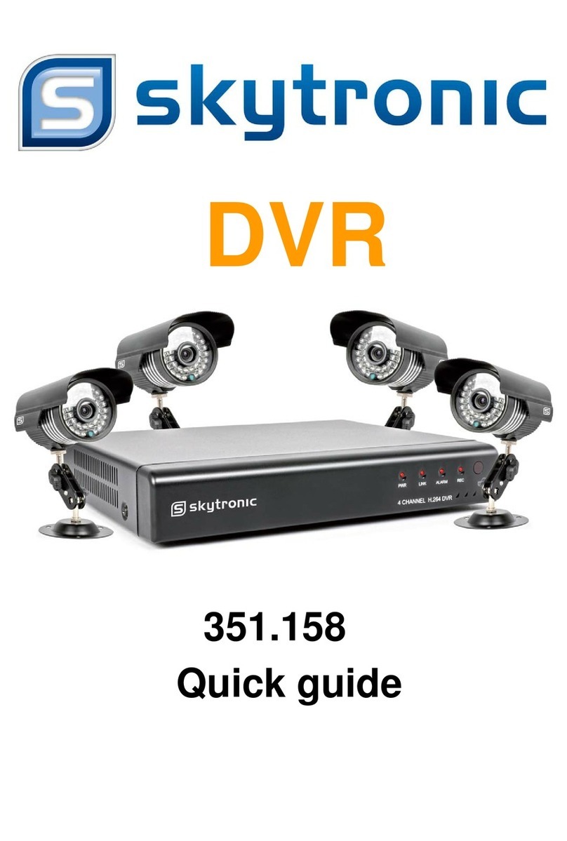
SKYTRONIC 351.158 User manual

SKYTRONIC
SKYTRONIC 351.180 User manual

SKYTRONIC
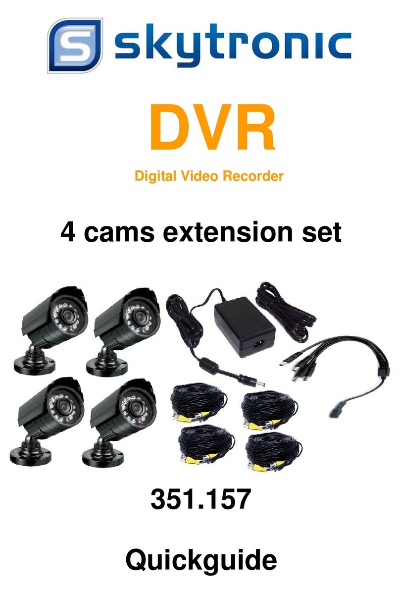
SKYTRONIC 351.157 User manual

SKYTRONIC
SKYTRONIC DVR User manual

SKYTRONIC
SKYTRONIC 351.124 User manual

SKYTRONIC
SKYTRONIC 351.154 User manual

SKYTRONIC
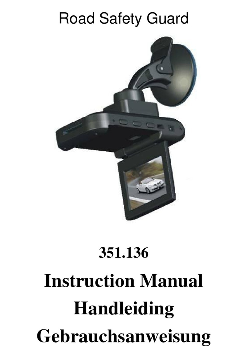
SKYTRONIC 351.136 User manual

SKYTRONIC
SKYTRONIC 351.154 User manual

SKYTRONIC
SKYTRONIC 351.158 User manual

SKYTRONIC
SKYTRONIC 351.174 User manual