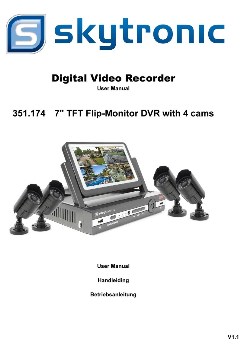
SKYTRONIC 351.174 User manual

Digital Video Recorder
User Manual
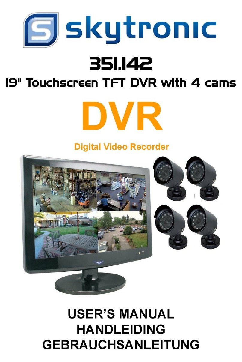
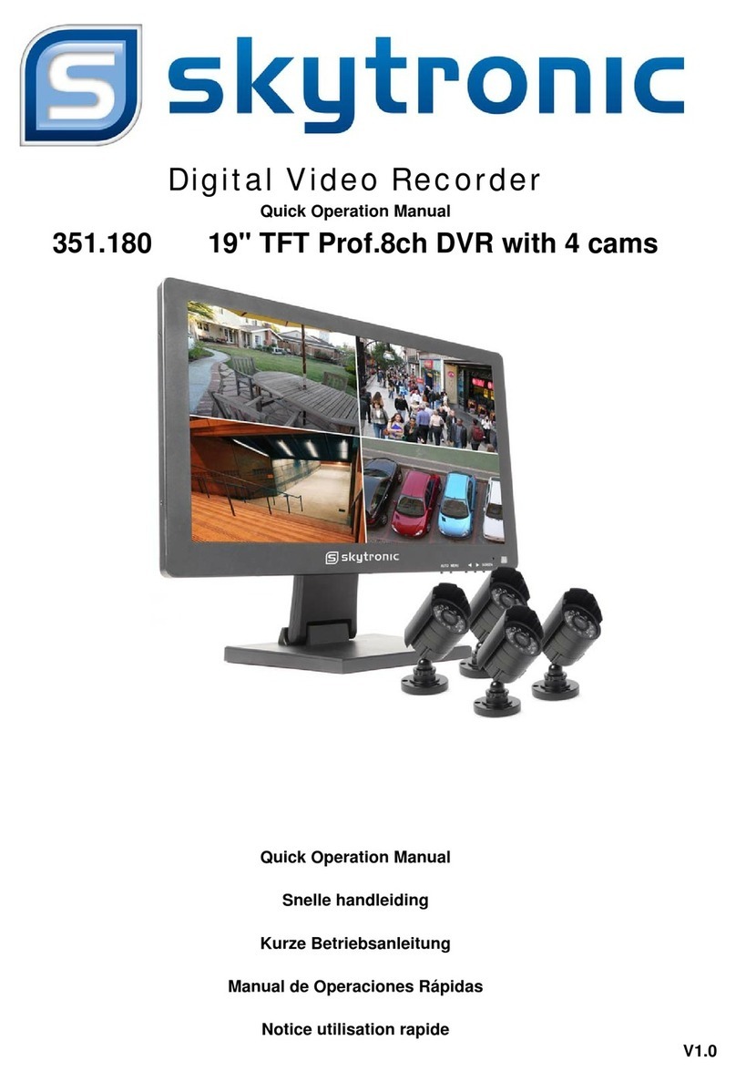
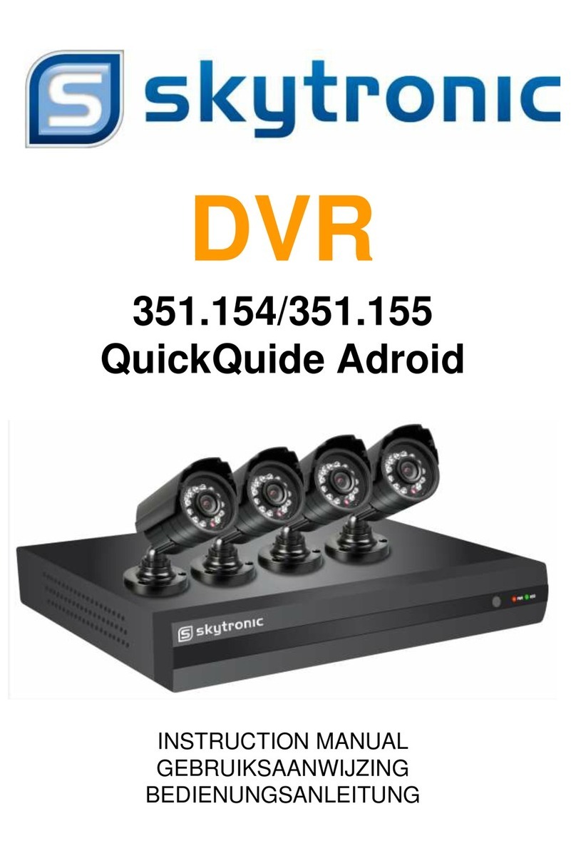
351.174 7" TFT Flip-Monitor DVR with 4 cams
User Manual
Handleiding
Betriebsanleitung
Manual del usuario
Notice d'utilisation
V1.0

1 - OPERATING PRECAUTIONS
• Do not install the video surveillance kit in locations with extreme humidity and/or temperatures, or where there is a risk the
equipment might rust or be exposed to dust. Do not install the video surveillance kit in cold locations or locations subject to large
temperature fluctuations.
• The cameras must not be exposed to direct sunlight. Preferred locations are porches or covered areas.
• The cameras must not be installed in locations where the lens filter might be vulnerable to scratching or dirt.
• Never obstruct the monitor's ventilation holes.
• Do not daisy chain extension cords and/or multi-socket adapters.
• Do not install near acidic chemicals, ammonia or sources of toxic gasses.
• Do not install in explosive environments or near volatile or inflammable products.
• Never put objects containing water on top of the device.
• Never cover the device.
• The 19’’ video surveillance kit monitor and mains adapter must only be used indoors.
• Make sure that the device and power supply are well ventilated.
• Do not place the device or cameras near magnetic sources.
2 - MAINTENANCE AND CLEANING
• Always unplug the products from the mains before carrying out any maintenance.
• Never use abrasive or corrosive substances to clean the product.
• Use a soft, clean cloth or special LCD screen wipes.
• Never spray anything onto the product as it may damage the internal workings.
3 – RECYCLING Disposing of used batteries in the household waste is strictly forbidden. Batteries/accumulators containing
harmful substances are marked with symbols (shown opposite) which indicate that it is forbidden to discard them in the
household waste. The corresponding heavy metal designations are as follows: Cd = cadmium, Hg = mercury, Pb = lead. You can
dispose of these batteries/accumulators at local recycling amenities (centres for sorting recyclable materials) which are required
to accept them. Keep batteries/button cells/accumulators out of reach of children and store them in a safe place not accessible to
them as they could be swallowed by children or domestic animals. May be fatal if swallowed. In the event that a battery is
swallowed, consult a doctor or go to A&E immediately. Never short-circuit the batteries, and do not burn or recharge them. as
there is a danger they might
explode.
This logo denotes that devices which are no longer used must not be disposed of as household waste. as they are likely to
contain hazardous substances which are dangerous to health and the environment. Take these devices back to your dealer or
use your council's selective recycling facilities.
Thanks for buying our digital video recorder
Safety Precautions:
To avoid risks and possible loss of property, please be sure to follow the right operations
printed in the manual
Please place and use the product under the environment 0℃-55℃,avoid place it in humid
environment
Avoid direct sunlight or heat sources
Avoid humid ,dusty or smoky environment
Keep the device in horizontal installation condition
Installing it in stable sites, avoid downfall
Please don’t place other devices on the DVR
Install DVR in well-ventilated sites, avoid blocking the vents
Use it under rated input and output range
Please don’t disassemble the DVR at will
Installation
1.1Open Package Check
First, please check whether any visible damage to the package appearance. The protective materials used for the package of the
DVR can protect most accidental clashes during transportation.
Then, checking if all accessories are equipped
1.2Connection Diagram
Declaration:
Incorrect description of technology and printing may be included in this manual, we’ll update it
irregularly without prior notice; updated contents will be printed in new version. we’ll keep on
improve the program or update the description of manual. if any inconformity, please in kind
prevail!

1.3Back Panel Instructions
Instruction: Different models with different functions, please in kind prevail, details please refer to following table.
Identification Name Description
Video in Video input 1-8CH multi-channel video input(BNC)
Audio in Audio Input 1-8CH multi-channel audio input(RCA)
Video out Video output Video output
Audio out Audio output Audio output
VGA VGA port VGA output
HDMI HDMI port HDMI output
USB USB port
USB2.0,used for USB mouse, USB memory stick,
LAN LAN port
10/100M Adaptive Ethernet Card(RJ45)
DC/AC Power input DC 12V/4A,
1 - Contents of the kit
1. 19’’ LCD DVR COMBO
2. Hard Disk Mounting Hardware Packet
3. Remote control
4. USB mouse
5. Video cameras
6. AC/DC adapter
1 – Installing the monitor
The monitor included in your video surveillance kit is equipped with a swiveling base which can either be fixed to a vertical or
horizontal bracket. Vertical installation requires 4 screws and wall plugs (not included) to suit the bracket type.
Warning: If mounting the unit on a wall, ensure appropriate wall plugs for the bracket (capable of supporting over 5.8 kg in
weight) are used.
2 - Installing the cameras
• The cameras can be fitted either to a wall or the ceiling.
• Undo the 2 camera screws to angle them as required. Tighten them again when you are happy with the adjustment.
• Mount the cameras using screws and wall plugs that are appropriate to the type of bracket (the screws and wall plugs provided
are suitable for solid walls).
• Ensure the cameras are properly secured to prevent them from falling.
Accessing the display settings
To access the monitor settings, press the MENU key on the front of the monitor. When you press the key, the following settings
will
be displayed:
From this menu:
• The MENU key takes you into the highlighted menu or selects the highlighted option.
• TheAUTO key takes you up a menu level.
• The left and right keys are used for adjusting the settings in the highlighted option or navigating the menus.

• Colour: adjusts the brightness, contrast and colour of your screen.
• Image Setting: for manually adjusting the position of the image on the screen (theAUTO key performs the same function
automatically if pressed when not in the menu).
• OSD Menu: allows you to adjust the position and length of time the menu is displayed
• Signal source: not used on this model
• Volume: used to adjust the sound volume of the monitor's integral loudspeaker (can also be set using the left and right keys
when not in the menu)
• Setting: allows you to reset the screen settings
CONTEXT MENU
A context menu can be opened by right-clicking on the mouse:
See 1: allows you to choose one camera feed to display on-screen from the 8 available. Click on the desired camera feed from
the list displayed. You can also doubleclick on one of the image feeds.
See 4: allows you to choose 4 camera feeds to display on-screen from the 8 available. Click on the desired group of camera
feeds from the list displayed.
See 9: displays all 8 of the available cameras simultaneously on-screen.
• P/T/Z: if one of your cameras is motorized and connected to the screen, this displays the controls so that you can control it.
Colour settings: adjusts the display settings. Warning: unlike the keys on the front of the monitor, any adjustments made here
will affect all the connected screens.
Search: allows you view recordings that are stored in the memory
Record: allows you to easily start or stop recording a camera feed. Select [Calendar] to follow the schedule programmed into
your monitor, [Manual] to force a recording to start, or [Stop] to force a recording to stop.
Alarm output: used for activating or stopping alerts and notifications from your cameras (motion detection, image loss, etc.)
Main menu: displays the main settings menu.
Logging in
When the 19" colour video surveillance kit is powered up (by pressing the on/off button), the system will display the feed from one
or more of the connected cameras. Right-click on the mouse, then click on [Main menu] to bring up the settings for your 19"
colour video surveillance kit: The default ID is admin. The default password is 123456 (click on the [password] field to bring up
the
numerical keypad).

MAIN MENU TREE
Each icon corresponds to a group of settings:
SEARCH: Allows you to find recordings for a given date or time slot. Also allows you to backup videos to removable USB media.
CONFIGURATION: Provides access to the date and time settings, recordings programming, network settings if the video
surveillance kit is connected to a computer network or the internet, alert settings and their effects, and ID and password
management.
MAINTAIN: Provides access to the recorder status: events log, device version number, reset to factory settings, memory space
used, automatic deletion, and list of users connected locally or remotely.
OUTPUT: Provides access to the motorized camera settings, activation or stopping of camera alerts and notifications (on motion
detection, image loss, etc.), the behavior settings for your video surveillance kit serial connection, screen resolution setup, and
whether the time, channel names, etc. are displayed.
STORAGE: Provides access to the status and management of the hard disk (included) and the backup to USB media functions.
SHUT DOWN:Allows you to lock, shut down or restart the video surveillance kit.
SEARCH menu: This menu allows you to view all the recordings stored on the hard disk.
CONFIGURATION menu: This menu provides access to your video surveillance kit's main settings:

SYSTEM: This allows you to adjust the date, time, 12/24 hour clock format, display language and the network name of your
device.
Calendar: The calendar indicates the presence of recordings in the memory (with dates highlighted in green). The red frame
denotes the day's date. First, select the day you wish to view, then the requisite channel number(s) under the calendar.
Playback controls: These controls allow you to start forward or backward playback, fast forward and fast rewind of the video in
progress.
Details of the selected day : This displays the details of the day you selected in the calendar. The colour bands show the
presence and type of recording in the memory. Click on the checkboxes at the bottom to hide or display given types of recording.
List mode: This button toggles between the graphical calendar display and a list of video recordings sorted by chronological
order.

Setup Record:
Basic tab: Allows you to choose the size, compression, frame rate (No. of images per second), sound recording/no sound
recording (if an audio source is connected to RCA (phono) inputs 1 to 4 - option not available for the other channels).
Recording schedule tab: Used for programming the recording time slots for each of your cameras. Select the desired channel,
then click on the Set button for the relevant day. Pre-Recording time: Field shows the length of the recording prior to triggering.
For example, if you activate recording on motion detection with 5 seconds of pre-recording time, your recording will also include
the 5 extra seconds before the movement which triggered the recording.
Setup Network:
Provides access to all the settings related to communication over the internet.
Basic tab: You can manually configure your recorder's (wired) network properties if you connect an internet access cable to the
network socket. Tick DHCP if you want all the settings to be entered automatically.
Advanced tab: This provides access to the advanced network settings.
Important notes:
- You can use this tab to configure the email alerts and FTP server connection by clicking on the relevant buttons.
- Other settings accessible here require advanced networking knowledge and are only of use under special circumstances.
These settings should only be changed if absolutely necessary.
Network State tab: Shows the current network settings.
P2P tab: Allows you to activate the plug and play feature so that you can access your video surveillance kit from any computer or
your smartphone or tablet.
Important note: The ID and password you will need for remote viewing are provided here.
EN

ALARM SETUP
This menu allows you to manage the wired input contacts (under the monitor) and the motion detection settings.
Local alarm tab: This tab is used to adjust the types and effects of each of the monitor's wired inputs (E.g. a wired sensor not
included in the kit which triggers recordings).
Internet alarm tab: not used on this model.
Detect tab: This tab is used to configure the motion detection, monitored area coverage [Coverage setup] button and the
behavior to adopt [Process] button.
You can also use this tab to activate alerts if the feed from a camera is lost or if the field of view of a camera is accidentally
obstructed.
ACCOUNT
This displays the IDs and passwords used for logging in to the monitor (including the default admin account/password). This
section is used to create additional users should you not wish to divulge the default "admin" account and password. It also allows
you to change existing accounts and passwords.
Important note: the video surveillance kit keeps a log in the memory of all the actions carried out on the device. Creating an
account for each separate user is more secure because each action is logged under the name of the account that carried it out.

ANOMALOUS EVENTS
This is used to define the behavior to adopt should a hard disk, internet connection or network problem occur.
MAINTENANCE Menu
This menu allows you to view the status of your video surveillance kit and maintain the system.
LOG
All the events, actions and operations carried out on the video surveillance kit are shown here in alphabetical order
Output menu
VERSION Allows you to update the system. Not used in normal operation.

DEFAULT Used for restoring your equipment to its factory settings.
[DATA RATE] Provides you with real-time information on how much memory each camera is using.
AUTO MAINTENANCE
This is used to set an automatic restart time if required, or automatic file and video deletion after a given length of time.
Important note: there may be a legal time limit on keeping video footage. Please check the local legislation in force.
[USERS ONLINE] Provides a real-time display of locally or remotely connected users.
Menu This menu is used to manage and control motorized cameras, the display of visual alerts and other display functions.
ALARM OUTPUT
Used for activating or deactivating the messages which appear on-screen when a trigger, error or problem occurs.
DISPLAY
[Graphical interface] tab: This is used to overlay data onto the camera feed displayed on-screen: channel name, transparency
and time.
[Output setup]

tab: This tab is used to adjust the on-screen position of the image along with its colour, brightness and contrast.
Important note: Use this tab to set the screen resolution.
[Tour config] tab:
This tab is used for adjusting automatic on-screen camera feed scrolling and pause length.
Important note: This setting has no effect on the recordings you have configured: they will be actioned even if the feed from the
camera in question is not being displayed.
SHUTDOWN menu
Used to log off, shutdown or restart. Using the [Log off menu] function will require a valid user name and password to be entered
to log back in to the general menu. The [Shutdown] function shuts down all the video surveillance kit functions, disconnects any
remote users and asks you to press the on/off switch.
EN
OPERATION

Comment: When reading this chapter, it is assumed that your 19" video surveillance kit has already been installed and set up. If
this is not the
case, please refer to the previous chapters (on setting up your system).
19’’ ISmart IP video surveillance kit features
• Recordings can either be continuous or triggered when motion is detected in the field of one of the cameras, or they can be
triggered manually or at programmed intervals.
• The motion detection area for triggering a recording can be restricted to part of the screen (the size and location on the screen
can be adjusted).
• Real-time video compression and recording. H.264 video and ADPCM audio compression.
• Digital zoom for zooming in to specific parts of the screen.
• Automatic recovery function which restarts the system after a power outage or the signal from one of the cameras is lost.
• The mouse included in the kit can be used to configure the system; other methods include configuration by a computer on the
local network or over the internet, or using the remote control provided.
• Remote viewing, surveillance and control over the internet on a computer or a smartphone.
• Sending of email alerts after an event has been triggered.
• Backing up of recordings to external USB storage media or USB disk writer, or transfer of data over the Ethernet network.
• The system provides hassle-free remote access over the internet with no complicated settings to configure. All the system's
features can be accessed via computer or smartphones and tablets (iOS orAndroid).
REMOTE OPERATION (NETWORK)
You can access all your video surveillance kit's channels remotely over the internet using any of the following methods:
• a computer connected to the internet (no additional software required, just a web browser such as Chrome, Safari, Firefox or
Internet Explorer)
• an Android smartphone or tablet connected to the Internet
• an iPhone, iPod or iPad
1 - START-UP
Your video surveillance kit needs to be connected to the internet via network cable (through a modem/router, router or modem).
Go to your video surveillance kit menu using the mouse, then from the [main menu], go to the CONFIGURATION [SETUP]
[ NETWORK] menu. Click on the P2P tab:
2 - REMOTE VIEWING USING A COMPUTER
To view your camera feeds remotely, log on to the www.vssweb.net website. Depending on what equipment and browser you

are using, you may be asked to install an additional module: If this is the case, you should accept the request.
Comment: If your browser refuses to connect or the module needs to be installed, please contact your network administrator or
switch to a Firefox or Chrome browser. Once you have logged on with your ID and password, the home page will be displayed.
3 - REMOTE VIEWING USING A SMARTPHONE OR TABLET
A simplified version of the interface can be downloaded from the App Store or Google Play. Install the IMSeye app on your
smartphone or tablet:
Click on the 'add device' button to bring up the ID and password of your video surveillance kit: Once confirmed, click on the
name of your device to display the list of cameras: Next, click on the requisite camera to start displaying its feed: Although you
can connect up to 4 cameras at the same time, a good internet connection is needed. to maintain acceptable quality and frame
rate when 4 camera feeds are being transmitted at the same time. Screen currently selected list of cameras connected to your
video surveillance kit. Click on one of these dots to display the feed from the corresponding camera in the screen currently
selected. Click on 'Master stream' to display (or stop displaying) the feeds from all of your cameras in the order of your video
surveillance kit. You can select a different screen arrangement here should you wish to. Device name (of your choosing) Select
P2P If you are near your video surveillance kit, you can click here to scan the QR code for your video surveillance kit to avoid
having to enter its ID and password.
Identifiant [ID]: enter your Device ID here
[Password]: type in the password you entered in your video surveillance kit settings.
Technical and legal information
Functional characteristics
19’’ video surveillance kit
• Can be installed vertically (fixed to a wall).
• Up to 8 wired cameras can be connected via BNC
• The entire system can be controlled by the remote control included in the kit or using a wired mouse.
• Several user accounts can be configured.
• The images can be displayed on an HDMI screen or on monitors (using the BNC output).
• Option to record onto a SATA hard disk or a USB key.
• Manual or programmed recording over a given period.
• Software motion detection alert.
• Option to install a wired 12V alarm (siren) or wired detectors.

• Option to search for recordings by date or file.
• Option to use an image mask when recording (for outdoor recordings).
• Option to receive alerts by email or smartphone and to view the live images.
• Option to view the video feeds in Internet Explorer, Chrome, Firefox, Android or iOS.
Camera
• Suitable for outdoor use in a sheltered location: yes
• Adjustable mount: yes
• Fixing bracket: for wall or ceiling installation
• Anti-glare lens hood: yes
• Integrated microphone: no
• Night vision: yes at 15 m
• Protection Rating: IP66
SAMPLE EMAIL ALERT SETTINGS
When setting up and using email alerts, you can use up to 4 email addresses: one for sending the alerts and the remaining 3 for
receiving them in
case of motion detection, loss of connection to one of the cameras, hard disk problems, etc. To access the email alert
configuration, from the main menu of your video surveillance kit, go to the [Network] menu and go into the [advanced] tab.
Click on Email: [Setup]. Sample sending address created on www.gmail.com:
• SMTP [SMTP server]: sending server of the email service. In our example, the www.gmail.com SMTPserver is smtp.gmail.com.
Please refer to your messaging service help to find out what your email settings are.
• Port: depends on your messaging service. In our example, www.gmail.com uses port 465. Please refer to your messaging
service help to find out
what your email settings are.
• [User name]: email sending address. E.g. [email protected] (the address you use must have been created
beforehand).
• [Password]: password for logging in to your email sending account (in this case, [email protected])
• [From]: name of the sender of the email you will receive in case of alert.
• [Title]: Subject of the email you will be sent in case of alert.
• [Recipient]: you can configure up to 3 recipient email addresses (regardless of their messaging servers)
• [Event interval]: sending delay between consecutive emails. Allows you to set a specific sending delay between two
consecutive alerts
• Activer SSL [Use SSL]: depends on the outbox messaging service (in our example, videosurveillance-home@gmail.com).
• Test: allows you to test the settings you have entered.
Handleiding
1 - VEILIGHEIDSVOORSCHRIFTEN
1 - GEBRUIKSVOORSCHRIFTEN

• Installeer geen videobewakingsset in een extreem vochtige omgeving, bij extreme temperaturen en op plekken waar het kan
roesten of onder het stof komen te staan.
• Installeer geen videobewakingsset op een koude plek of op een plek waar grote temperatuurschommelingen zijn.
• De camera's mogen recht rechtstreeks aan zonlicht blootgestel worden. Een portiek of overdekte plaats genieten de voorkeur.
• De camera's mogen niet geïnstalleerd worden op een plaats waar de objectieffilter blootgesteld wordt aan krassen en vuil.
• Blokkeer de ventilatieroosters van het scherm niet.
• Vermeerder de stekkerbakken en verlengkabels niet.
• Plaats het niet in de buurt van chemisch zure producten, ammoniak of een emissiebron van giftige gassen.
• Plaats het niet op een plek waar ontploffingsgevaar heerst of in de buurt van vluchtige of ontvlambare producten.
• Er mag geen enkel waterrecipiënt onder het apparaat geplaatst worden.
• Bedek het apparaat niet.
• De videobewakingskit 19’’ en de adapter mogen enkel binnen gebruik worden.
• Let erop dat het apparaat en de voedingsbron goed geventileerd worden.
• Plaats het toestel en de camera's niet te dicht bij magnetische bronnen.
2 - ONDERHOUD EN REINIGING
• Voor ieder onderhoud moet u het product uit het stopcontact trekken.
• Reinig de apparaten niet met schurende of bijtende producten.
• Gebruik gewoon een zachte doek of speciale doekjes voor LCD schermen.
• Besproei het niet met een spuitbus want dit zou het binnenwerk van het product kunnen beschadigen.
3 - RECYCLAGE
Het is verboden gebruikte batterijen in een gewone vuilbak te gooien. De batterijen/ accu's die schadelijke bestanddelen bevatten
zijn gemarkeerd met symbolen die duidelijk maken dat het verboden is ze in een gewone vuilbak te gooien. De symbolen van de
overeenkomstige zware metalen zijn de volgende: Cd= cadmium, Hg= kwik, Pb= lood. U kunt gebruikte batterijen/accu's
indienen bij inzamelpunten in uw gemeente (containerparken) die verplicht zijn te recycleren. Leg geen batterijen/
knoopcelbatterijen/accu's binnen bereik van kinderen, bewaar ze op een plek die niet voor hen toegankelijk is. Het risico bestaat
dat kinderen of huisdieren ze inslikken. Levensgevaarlijk! Als dit toch zou gebeuren, raadpleeg dan onmiddellijk een arts of ga
naar het ziekenhuis. Let erop dat u geen kortsluiting in de batterijen veroorzaakt, gooi ze niet in vuur of probeer ze niet te
herladen. Er bestaat risico op ontploffing!
Het pictogram betekent dat apparaten die buiten gebruik zijn niet bij het huisvuil gegooid mogen worden. Eventuele
gevaarlijke onderdelen kunnen de gezondheid en het milieu schaden. Breng deze apparaten terug naar uw verdeler of maak
gebruik van de selectieve afvalinzameling in uw gemeente.

Bedankt voor het kopen van onze digitale video recorder
Veiligheidsmaatregelen:
Om risico's en mogelijke verlies van eigendom te voorkomen, moet u ervoor zorgen om de
juiste handelingen gedrukt in de handleiding te volgen
Gelieve het product niet te plaatsen en te gebruiken in de omgeving van 0℃-55℃, Please
place and use the product under the environment 0℃-55℃, vermijd plaatsen in vochtige
omgeving
Vermijd direct zonlicht of warmtebronnen
Houd het apparaat in horizontale montage conditie
Het installeren in stabiele sites, voorkomt vastlopen
Gelieve niet andere apparatuur op het apparaat aan te sluiten
Installeer de DVR in goed geventileerde plaatsen, Voorkom het blokkeren van de
ventilatieopeningen
Gebruik het onder nominale input en output range
Gelieve de DVR niet uit elkaar halen naar believen
Verklaring:
Onjuiste beschrijving van de technologie en afdrukken kunnen zijn opgenomen in deze
handleiding, we zullen het onregelmatig updaten zonder voorafgaande kennisgeving;
bijgewerkte inhoud zal in nieuwe release worden afgedrukt . We zullen het programma blijven
verbeteren of de beschrijving van de handleiding bijwerken. Eventuele ongelijkvormigheid,
kunt u in natura prevaleren!

Installatie
1.1Open Verpakkings Controle
Ten eerste, controleer of er zichtbare schade aan het pakket verschijnt. De beschermende materialen die worden gebruikt voor
het pakket van de DVR beschermen de meeste accidentele botsingen tijdens het transport.
Vervolgens controleren of alle accessoires zijn voorzien
1.2 Connection Diagram
1.3Achterpaneel instructies
Instructie: Verschillende modellen met verschillende functies, kunt u in natura prevaleren, details verwijzen wij u naar
onderstaande tabel.
Identification Name Description
Video in Video input 1-8CH multi-channel video input(BNC)
Audio in Audio Input 1-8CH multi-channel audio input(RCA)
Video out Video output Video output
Audio out Audio output Audio output
VGA VGA port VGA output
HDMI HDMI port HDMI output
USB USB port
USB2.0,used for USB mouse, USB memory stick,
LAN LAN port
10/100M Adaptive Ethernet Card(RJ45)
DC/AC Power input DC 12V/4A,

1 - Inhoud van DE KIT
1. 1LCD scherm 19’’ met geïntegreerde digitale recorder
2. Hard Drive en montage van accessoires
3. 2Afstandsbediening
4. 3USB muis
5. 4Videocamera’s
6. Adapter 12V DC
1 – Installatie van het scherm
Het scherm is van uw videobewakingskit is uitgerust met een scharnierende voet en kan ofwel op een verticale of een horizontale
steun vastgemaakt worden. Bij montage in verticale positie, heeft u 4 niet meegeleverde schroeven en bouten nodig, aan te
passen aan het materiaal van de steun.
Let op: Bij het vastmaken aan de muur moet u bouten gebruiken die geschikt zijn voor het materiaal van de steun zodat ze een
gewicht van meer dan 5,8kg kunnen dragen.
2 - installatie van de camera's
• De camera's kunnen tegen de muur of tegen het plafond geïnstalleerd worden.
• Schroef de 2 schroeven van de camera’s los om ze te draaien in de richting die u wenst. Zodra ze ingesteld zijn, schroeft u ze
weer vast.
• Maak de camera's vast met behulp van geschikte schroeven en bouten, aangepast aan het materiaal (Schroeven en bouten
geschikt voor muren, in vol materiaal).
• Let erop dat de camera's stevig vastzitten zodat ze niet los komen.
TOEGANG TOT DE WEERGAVEINSTELLINGEN
Om toegang te krijgen tot de scherminstellingen, drukt u op de toets MENU aan de voorkant van het scherm. Door op deze knop
te drukken, krijgt u toegang tot de volgende instellingen:
Vanuit dit menu:
• Met de toets MENU heeft u toegang tot het oplichtende menu of kunt u de oplichtende optie selecteren.
• Met de toetsAUTO kunt u naar het hoger liggende menu.
• Met de linker en rechter toets kunt u de oplichtende optie instellen of u verplaatsen in de menu's.
• Color (Kleur): hiermee kunt u de belichting, contrast en de kleur van het scherm aanpassen.
• Image Setting (beeldinstelling): hiermee kunt u manueel de positie van het beeld op het scherm aanpassen (de toets AUTO
doet dit automatisch
wanneer u buiten het menu klikt).
• OSD Menu: hiermee kunt u de positie en de weergaveduur van het menu instellen.
• Signal source (Bronsignaal): wordt bij dit model niet gebruikt.
• Volume: hiermee kunt u het volume van de luidspreker die in het scherm geïntegreerd is, instellen (kan ook via de linker en
rechter toetsen buiten het menu ingesteld worden).
• Setting (insteling): hiermee kunt u de scherminstellingen opnieuw instellen.

SNELMENU
Er is een snel menu toegankelijk wanneer u rechts klikt met de muis:
• Zie 1: maakt het mogelijk een camera op het scherm te tonen tussen de 8 beschikbare ingangen. Klik op de gewenste camera
in de lijst die verschijnt. U kunt ook dubbelklikken op het beeld van een van de camera's.
• Zie 4: maakt het mogelijk 4 camera's gelijktijdig te tonen tussen de 8 beschikbare ingangen. Klik op de gewenste cameragroep
in de lijst die verschijnt.
• Zie 9: toont de 8 beschikbare camera's gelijktijdig op het scherm
• P/T/Z: als een van uw camera’s gemotoriseerd is en aangesloten is op het scherm en de controles toont die deze kunnen
draaien.
• Instelling van de kleur: Wijzig de weergaveinstellingen. Opgelet: in tegenstelling tot de toetsen aan de voorzijde van het
scherm, hebben de aangebrachte wijzigingen hier invloed op alle aangesloten schermen.
• Zoeken: hiermee kunt u de opnames in het geheugen raadplegen
• Opname: hiermee kunt u gemakkelijk de opname van een camera starten of onderbreken. Kies (Kalender) om de
programmatie in het scherm te volgen, (Manueel) om het starten van een opname te forceren, (Stoppen) om het stoppen van de
opname te forceren.
• Alarmuitgang: hiermee kunt u de alarmen en waarschuwingen van uw camera's starten of stoppen (bewegingsdetectie,
beeldverlies, enz.)
• Hoofdmenu: toont het configuratie hoofdmenu.
Inloggen
Na inschakeling (druk op de start/stop knop) toont de kleuren videobewakingskit IP 19’’ het beeld van de aangesloten camera('s).
Rechtsklik en klik
vervolgens op (hoofdmenu) om toegang te krijgen tot de instellingen van uw videobewakingskit IP 19’’: De standaard gebruikers
is admin. Het standaard wachtwoord is 123456 (klik in het veld (wachtwoord) om het numerieke klavier tevoorschijn te halen).
Other manuals for 351.174
1
Table of contents
Languages:
Other SKYTRONIC DVR manuals

SKYTRONIC
SKYTRONIC 351.180 User manual

SKYTRONIC
SKYTRONIC 351.157 User manual

SKYTRONIC
SKYTRONIC 351.158 User manual

SKYTRONIC
SKYTRONIC 351.174 User manual

SKYTRONIC
SKYTRONIC 351.142 User manual

SKYTRONIC
SKYTRONIC 351.154 User manual

SKYTRONIC
SKYTRONIC DVR User manual

SKYTRONIC
SKYTRONIC 351.154 User manual

SKYTRONIC
SKYTRONIC 351.124 User manual

SKYTRONIC
SKYTRONIC 351.158 User manual