SLOPE INDICATOR 56804199 User manual

Copyright ©2006 Durham Geo Slope Indicator. All Rights Reserved.
This equipment should be installed, maintained, and operated by technically qualified personnel. Any errors
or omissions in data, or the interpretation of data, are not the responsibility of Slope Indicator Company. The
information herein is subject to change without notification.
This document contains information that is proprietary to Slope Indicator company and is subject to return
upon request. It is transmitted for the sole purpose of aiding the transaction of business between Slope Indi-
cator Company and the recipient. All information, data, designs, and drawings contained herein are propri-
etary to and the property of Slope Indicator Company, and may not be reproduced or copied in any form, by
photocopy or any other means, including disclosure to outside parties, directly or indirectly, without permis-
sion in writing from Slope Indicator Company.
SLOPE INDICATOR
12123 Harbour Reach Drive
Mukilteo, Washington, USA, 98275
Tel: 425-493-6200 Fax: 425-493-6250
E-mail: solutions@slope.com
Website: www.slopeindicator.com
EL In-Place
Inclinometer
56804199

EL In-Place Inclinometer, 2008/7/09
Contents
Introduction. . . . . . . . . . . . . . . . . . . . . . . 1
Pre-Assembly . . . . . . . . . . . . . . . . . . . . . 5
Vertical Installation . . . . . . . . . . . . . . . . 6
Horizontal Installation . . . . . . . . . . . . .11
Manual Reading . . . . . . . . . . . . . . . . . . 14
Data Logging. . . . . . . . . . . . . . . . . . . . . .16
Data Reduction. . . . . . . . . . . . . . . . . . . .18
Removing Sensors. . . . . . . . . . . . . . . . .23

EL In-Place Inclinometer, 2008/7/09 1
Introduction
In-Place
Inclinometers
The in-place inclinometer system consists of
inclinometer casing and a string of linked
in-place inclinometer sensors.
The inclinometer casing provides access for sub-
surface measurements, controls the orientation of
the sensors, and moves with the surrounding
ground.
In vertical installations, the inclinometer casing is
installed in a borehole that passes through a sus-
pected zone of movement. One set of grooves is
aligned in the expected direction of movement
(downhill, for example).
In horizontal installations, inclinometer casing is
typically installed in a trench. One set of grooves
must be aligned to vertical, since the instrument is
expected to monitor vertical movements (settle-
ment or heave).
The string of linked sensors is positioned inside
the casing to span the zone of movement. When
the ground moves, the casing moves with it,
changing the inclination of the sensors inside the
casing.
Sensors for vertical installations measure inclination from vertical. Sen-
sors for horizontal installations measure inclination from horizontal.
Inclination measurements from the sensors are processed to provide
displacement readings in mm of displacement for the gauge length of
each sensor.
In most applications, sensors are connected to a data acquisition system
and data processing is completed by a computer program.
Casing
controls
orientation
of sensors
Fixed wheel
points at
direction of
movement
in vertical
installations
Sensor
gauge
length
Inclinometer casing controls the orientation of the sensor
Sensor gauge length
Fixed wheel points down
in horizontal installations
ExpectedDirection
ofMovement
In vertical installations, one
pair of casing grooves should
be aligned with the expected
direction of movement.
In horizontal installations, one
pair of casing grooves must be
aligned to vertical.
Vertical
EL In-Place Inclinometer, 2008/7/09 2
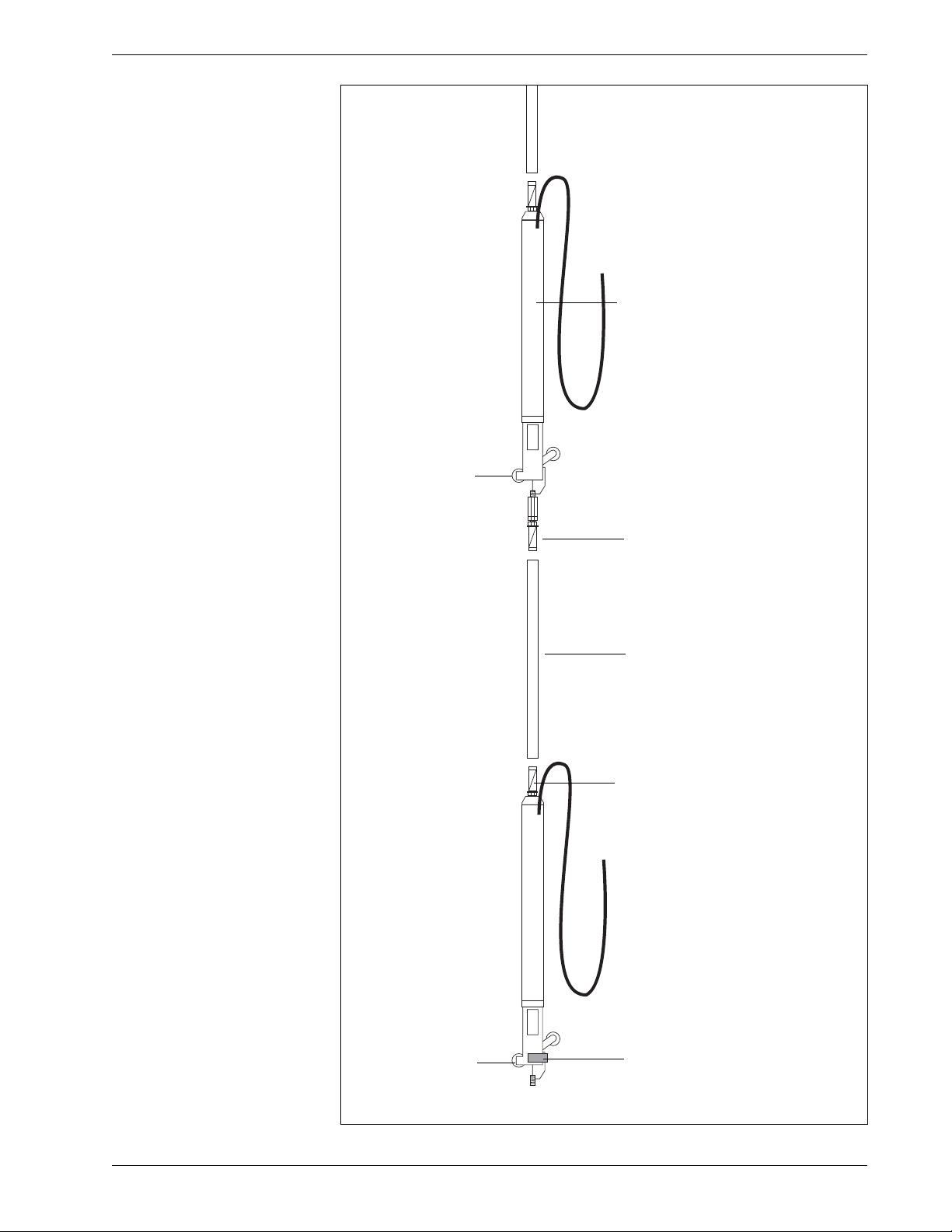
IPI Sensor
Components
IPI sensor with wheel
assembly and top and
bottom tubing clamps.
Each sensor has a serial
number and is sup-
plied with a specified
length of signal cable.
Tubing clamp connects
sensor to gauge tubing
Gauge tubing completes the
gauge length of the sensor
below. Typically longer than
shown here.
Tubing clamp connects the
sensor to the gauge tubing.
Bottom IPI sensor
includes a swivel clamp
to lock the bottom
wheel assembly.
Fixed wheel is
important at
installation
time.
Fixed wheel is
important at
installation
time.
EL In-Place Inclinometer, 2008/7/09 3
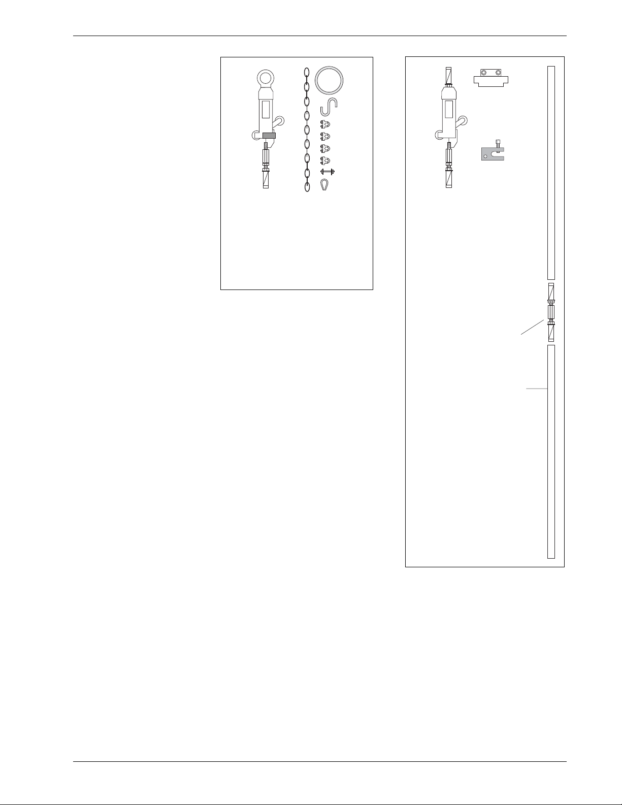
Other Components
Suspension Kit includes wheel
assembly and hardware to clamp
and adjust suspension cable.
Suspension kit is used with vertical
inclinometers. Stainless cable is
required, but not shown.
Placement tubing is used
to push inclinometer into
position and then keep it
there. Generally supplied
in 10 ft. or 3 meter
length.
Coupling for placement
tubing.
Placement Kit includes
wheel assembly and top
clamp. Clamp rests on top of
casing and hold placement
tubing in center of casing.
Placement kit is typically
used with horizontal IPI
installations, but can also be
used for vertical installations.

EL In-Place Inclinometer, 2008/7/09 4
Gauge Tubing Gauge tubing is typically ordered with the sensors. If gauge tubing is
not supplied, check project specifications for required gauge length,
and then follow the instructions below:
1. Choose stainless tubing that can accept tubing clamps. The standard
tubing clamps have a minimum OD of 15.6 mm (0.615 inch) and
expand to a maximum OD of 17.4 mm (0.685 inch).
2. Measure and mark the gauge tubing for the proper length:
tubing length = total gauge length – 550 mm (21.625 inch).
For example, you would cut tubing lengths of 1450 mm for a total
gauge length of 2 meters.
3. Cut and deburr the gauge tubing. Check that tubing clamps fit inside.
Suspension Cable Suspension cable, if used, is typically ordered with the system. The sus-
pension kit contains hardware for 3/16 inch cable. The cable is 3/16
inch, 19 x 7, stainless steel aircraft cable.
Placement Tubing Placement tubing, if used, is typically ordered with the system. If place-
ment tubing is required, but not supplied, follow the instructions below.
1. Choose stainless tubing that can accept tubing clamps and couplings.
The standard tubing clamps have a minimum OD of 15.6 mm (0.615
inch) and expand to a maximum OD of 17.4 mm (0.685 inch).
2. Deburr the gauge tubing and check that tubing clamps fit inside.
3. Use the coupling shown on previous page to join lengths of place-
ment tubing.
4. Use in-line wheel assembly if placement tubing must be articulated.
Safety Cable In vertical installations, you may find it useful to connect a safety cable
to the bottom sensor to prevent accidental loss of the sensors.
EL In-Place Inclinometer, 2008/7/09 5
Pre-Assembly
Introduction This chapter tells how to connect gauge tubing to the sensors. We do
not recommend further pre-assembly. Sensors should be joined to
other sensors only as they are installed downhole.
Tools •Vice-grips to hold gauge tubing.
•Wrench to tighten tubing clamps.
Identify and
Check Sensors
•Test each sensor. See “Manual Readings” for instructions.
•Write down the serial number and intended installation depth of
each sensor.
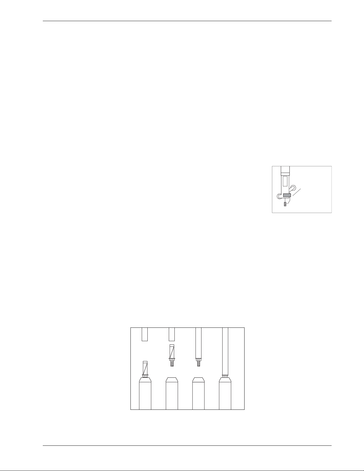
•Check that wheels are firmly attached to sen-
sors. Also check that the swivel clamp is
attached to the wheel assembly of the bottom
(farthest) sensor.
•Check that cable lengths are correct and attach
sensor ID tags to ends of signal cables.
•Mark sensors for order of installation.
Attach Gauge Tubing
to Each Sensor
As you work, be careful not to bend or damage the wheel assembly as
you work.
1. Remove the tubing clamp from the top of the sensor body.
2. Insert clamp into gauge tubing
3. Hold tubing and tighten clamp well.
4. Screw gauge tubing onto sensor body until sensor body and gauge
tubing form a rigid unit.
Swivel
clamp on
bottom
sensor
1234

EL In-Place Inclinometer, 2008/7/09 6
Vertical Installation
Overview 1. Lay out sensors in order of installation.
2. Insert the first sensor in the preferred set of grooves. The fixed wheel
should point toward the expected direction of movement.
3. Lower the sensor into the casing. Keep the top of the gauge tube
accessible.
4. Align the next sensor with the preferred set of grooves as in step 2,
and connect it to the gauge tubing of the downhole sensor.
5. Lower the sensors into the casing. Repeat steps 4 and 5 until all sen-
sors have been installed.
6. Prepare the suspension kit or the placement kit.
7. Lower the sensors to their final location and terminate the top.
Required Tools •Safety cable attached to bottom sensor to prevent loss of sensors
down hole.
•Vice grips (clamping pliers) for holding gauge tubing while
connecting adjacent sensors.
•Thin 17 mm wrench for tightening tubing clamps.
•Tools for cable clamps or Allen wrench for securing top clamp.
•Vinyl tape for securing cable to gauge tubing.
Preparations 1. Note serial number and position of each sensor.
2. Lay out sensors in order of installation. We do not recommend pre-
assembly of the string of sensors. Add sensors to the string one by
one as you install them downhole.
3. Keep cables coiled until sensor is installed.
Removal If it is necessary to remove sensors, take the following precautions:
•Never try to remove the assembled string of sensors. The weight and
leverage of long gauge lengths make it very easy to damage the
wheels.
•Always disassemble the string, sensor by sensor. When removing
each sensor, always clamp the gauge tubing of the downhole sensor to
prevent it from twisting.
EL In-Place Inclinometer, 2008/7/09 7
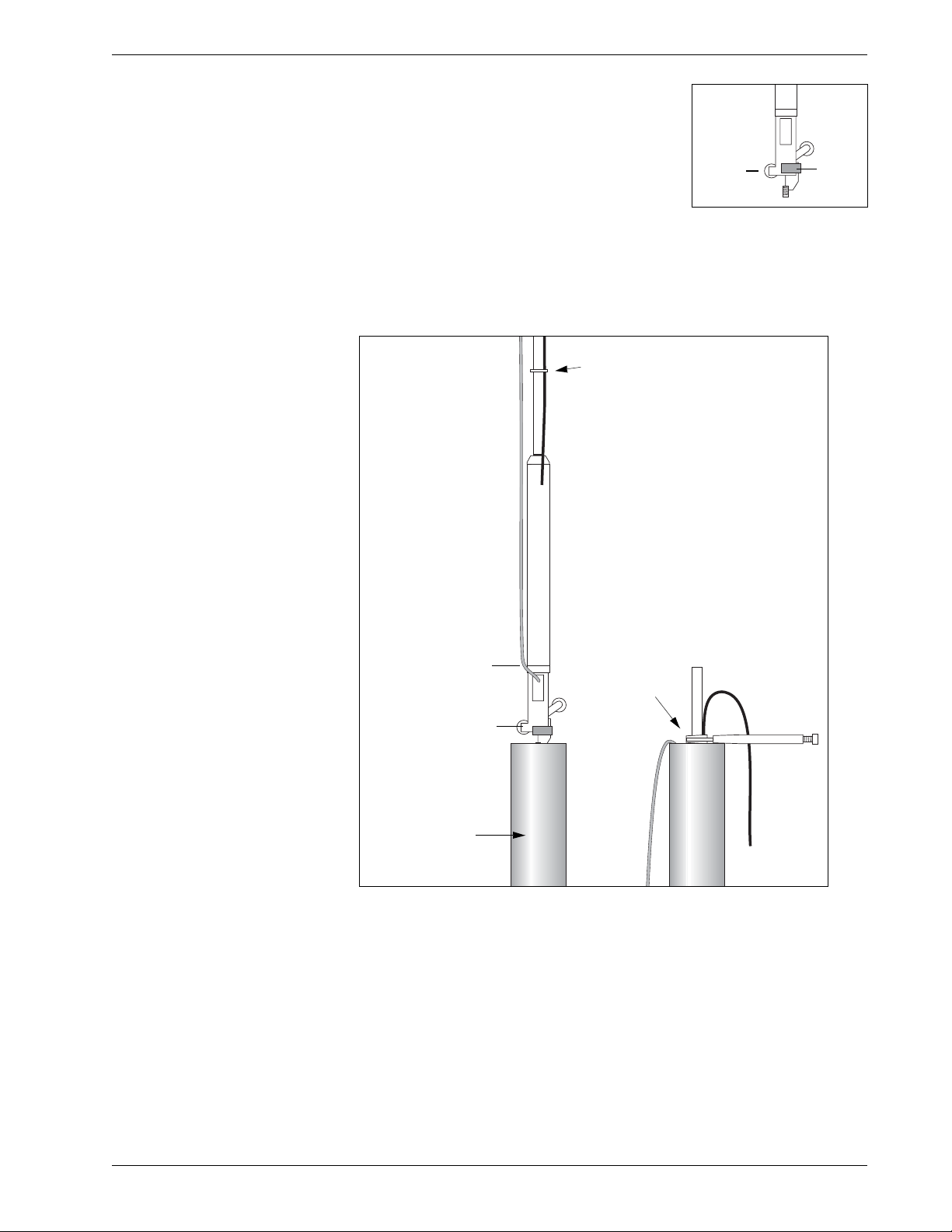
Install the
Bottom Sensor
1. Attach safety line (nylon or wire rope) to
bottom sensor. Secure the safety line.
2. Insert first (bottom) sensor in preferred set
of grooves. The fixed wheel should point to
the expected direction of movement. Check
that the wheel has a swivel clamp.
3. Lower sensor into casing. Tape signal cable to gauge tubing.
Use vice grips to clamp top of gauge tubing. Now the next sensor can
be installed.
Fixed
Wheel
Swivel
Clamp
Clamp gauge
tubing with
vice grip.
Tie a safety line (nylon
or wire rope) to the
bottom sensor.
Tape signal cable to gauge tubing.
Inclinometer
Casing
Fixed wheel should
point to expected
direction of move-
ment.

EL In-Place Inclinometer, 2008/7/09 8
Install Next Sensor Connect next sensor to the gauge tubing of the sensor below, as shown
in the drawing. Continue adding sensors until the sensor string is com-
plete. Keep the following points in mind:
•Do not allow the installed sensor to twist in the casing when you
tighten the connection. Twisting can damage the wheels or pop them
out of the grooves.
•When you lower the sensor into the casing, check that the fixed
wheel is aligned in the proper direction.
•Tape cables neatly, so that they do not cross each other.
Hold gauge
tubing firmly
so that it does
not twist.
Check that fixed
wheel is aligned with
proper groove.
Tighten tubing
clamp well.
Tape cables
neatly for
easier
installation.

EL In-Place Inclinometer, 2008/7/09 9
Install Top Wheel Attach top wheel from suspension kit or placement kit.
•Suspension kit: Wheel supplied in suspension kit has an eyelet for
suspension cable. Connect suspension cable as shown in drawing.
•Placement kit: Wheel supplied in placement kit has tubing clamp.
Attach placement tubing as shown in the drawing.
Check alignment of
fixed wheel and do
not twist gauge tube
when tightening nuts.
Suspension
Cable
Placement
Tubing

EL In-Place Inclinometer, 2008/7/09 10
Terminate
with Suspension Kit
The suspension kit is used with vertical
installations. It consists of a top wheel
assembly, shown on the previous page,
cable thimbles, cable clamps, and a
hook for the top of the casing.
1. Cut the suspension cable to the
appro-priate length.
2. Attach the cable to the top wheel
assembly using the thimble and
clamps.
3. Attach the other end of the cable to
the chain, as shown in the drawing.
4. Use the chain is used to adjust the
final depth of the sensors.
Terminate with
Placement Kit
The placement kit is sometimes used
with vertical installations. It consists of
a top wheel assembly, shown on the
previous page, and a “top” clamp for
placement tube.
The top clamp holds either placement
tubing - when the sensors are deeper in
the casing - or the gauge tube of the
nearest sensor.
The top clamp has a split collar. Loosen
the screws, slide the collar over the
placement tubing or gauge tubing, and
then tighten the screws.
Cable
thimble

EL In-Place Inclinometer, 2008/7/09 11
Horizontal Installation
Overview 1. Lay out sensors in order of installation.
2. Align the first sensor with the vertical grooves of the casing. Insert
the sensor with its fixed wheel pointing downwards.
3. Push the sensor into the casing. Keep the top end of its gauge tubing
accessible.
4. Connect the next sensor to the gauge tubing of the downhole sensor.
Then push it into the casing.
5. Continue connecting sensors until the string is complete.
6. Connect the final wheel assembly.
7. Prepare the placement kit and placement tubing.
8. Push push sensors to final location and terminate.
Required Tools •Safety cable may be useful if sensors are to be retrieved or if casing
actually slopes downwards.
•Vice grips (clamping pliers) for holding gauge tubing while
connecting adjacent sensors.
•Thin 17 mm wrench for tightening tubing clamps.
•Allen wrench for securing top clamp.
•Vinyl tape for securing cable to gauge tubing.
Preparations 1. Attach gauge tubing to each sensor, as explained previously. We do
not recommend joining sensors together now. Add sensors one by
one to the string.
2. Lay out sensors in order of installation. Note the serial number and
position of each sensor.
3. Keep cables coiled until sensor is installed.
Removal If it is necessary to remove sensors, take the following precautions:
•Never try to remove the assembled string of sensors. The weight and
leverage of long gauge lengths make it very easy to damage the
wheels.
4. Always disassemble the string, sensor by sensor. When removing
each sensor, always clamp the gauge tubing of the downhole sensor
to prevent it from twisting.
EL In-Place Inclinometer, 2008/7/09 12
Install the
First Sensor
1. Check that the first sensor has a swivel clamp on its wheel assembly.
2. Tape signal cable to the gauge tubing.
3. Align the fixed wheel with the bottom groove and push the sensor
into the casing.
Install More Sensors 1. Prepare to connect the next sensor. Align the fixed wheel with the
bottom groove.
2. Push the tubing clamp into the gauge tubing of the sensor that is
already in the casing. Do not twist the gauge tubing when you tighten
the tubing clamp nuts.
3. Continue adding sensors until the sensor string is complete.:
•Do not twist the installed sensor when you tighten tubing clamps.
Twisting can damage the wheels or pop them out of the grooves.
•Always verify that the fixed wheel is in the bottom groove.
•Tie cables neatly, so that they do not cross each other.
Swivel Clamp
Fixed Wheel
Fixed
Wheel
Tubing
Clamp
Do not twist gauge tubing.
Keep cable away from wheels.
Allow some slack at the swivel.
Arrange cables neatly so that they
do not cross. Ideally, cables should
not touch casing.

EL In-Place Inclinometer, 2008/7/09 13
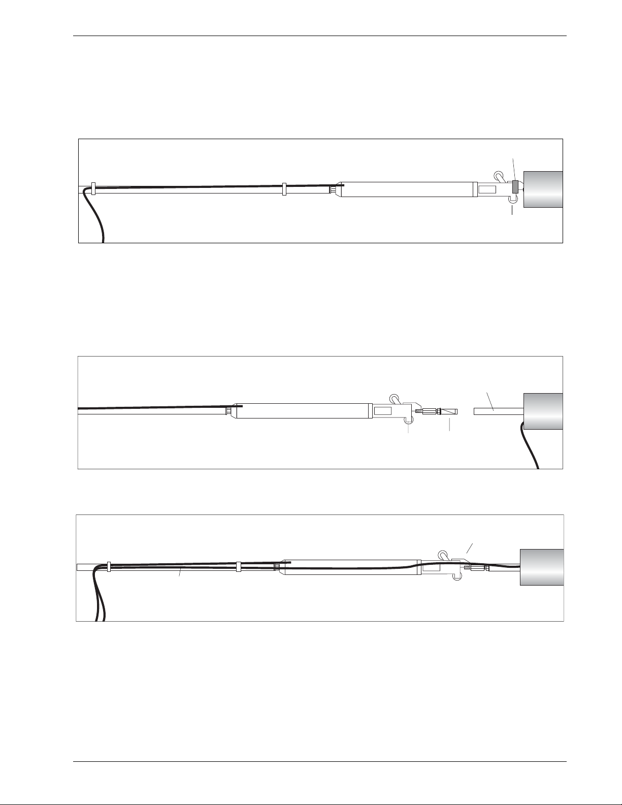
Terminating the
Installation
The placement kit supplies most of the components used to terminate
horizontal installations. The placement kit includes a top wheel assem-
bly and a top clamp. A top clamp retainer is also available.
Install Top Wheel The top wheel com-
pletes the gauge length
of the nearest sensor.
Align the fixed wheel
with the bottom
groove.
The top wheel is not required if the gauge length of the top sensor is ter-
minated with the top clamp.
Install
Placement Tubing
Placement tubing is used to position the sensors deeper into the casing.
Placement tubing is normally longer than shown in the illustration. A
coupling is used to join two placement tubes.
Install
Top Clamp
The top clamp holds placement tubing or the gauge tube of the nearest
sensor.
1. The top clamp has a split collar.
Loosen the screws, slide the collar over
the placement tubing or gauge tubing,
and then tighten the screw.
2. (Optional) Use the top clamp retainer
to hold the top clamp to the casing.
3. In horizontal installations, the sensors normally must be pushed into
the casing. This puts the mechanical linkage of the sensors into com-
pression. If possible, put the linkage into tension, but pushing the
sensors deeper into the casing and then pulling them back into
position.
Do not twist the sensors when
you tighten the tubing clamp.
Do not twist the sensors when you
tighten the tubing clamp.
Top
clamp
Top
clamp
retainer

EL In-Place Inclinometer, 2008/7/09 14
Manual Readings
Introduction Manual readings are useful for testing the system before the data acqui-
sition system is set up. This manual covers connections to IPI sensors
that have a 2.5v signal conditioner. Previous signal conditioners used a
250 mV signal conditioner with different wiring.
EL Data Recorder 1. Connect sensor to readout as shown in the table below.
2. Switch on. Choose uniaxial or biaxial sensor.
3. Tilt is displayed in volts. Temperature is displayed in degrees C.
Testing with
a Voltmeter
The voltmeter should be capable of displaying values in the low milli-
volt dc range. You must also have a power source must supply between
5.5 and 15 Vdc. An alkaline 9-volt battery is suitable
1. Connect green wire to the + terminal of the power source. Connect
the violet wire and black wire to the - terminal of the power source.
2. To read the A-axis sensor, connect the voltmeter to the orange wire
(signal) and yellow wire (reference).
3. To read the B-axis sensor, connect the voltmeter to the blue wire (sig-
nal) and yellow wire (reference).
4. To read the thermistor, connect the voltmeter to the red and yellow
wires.
Data Recorder Terminal Signal Cable Wire
1TiltA Orange
2TiltB Blue
3Temp Red
4 Sig Common Yellow
5Sense Violet
6 Power + Green
7Power- Black
8 Shield Drain Wire

EL In-Place Inclinometer, 2008/7/09 15
Test Readings 1. When the sensor body is vertical, you should see a reading of about
0.0 Vdc.
2. The A-axis sensor measures tilt in the plane of the wheels. Tilt the top
of the sensor in the direction of the fixed wheel. The reading should
be about 2.2 to 2.3 V as the tilt nears 10 degrees. Tilt the top of the
sensor in the direction of the sprung wheel. The reading should be
about -2.2 to -2.3 V as the tilt nears 10 degrees.
3. The B-axis sensor (available with biaxial sensors only) is rotated 90
degrees from the A-axis sensor. Tilting the sensor to 10 degrees
should provide a reading of ±2.2 to 2.3 Volts.
4. See the next section, data reduction, to learn how to convert the
reading in volts to deviation in mm.
5. At 25 degrees C, the thermistor reading should be about 1 Vdc.

EL In-Place Inclinometer, 2008/7/09 16
DataLogging
Data Logging
with CR10X
These instructions provide information needed for reading uniaxial
and biaxial IPIs with the Campbell Scientific CR10X datalogger system.
Sample Program: A sample CR10X monitoring program is available at
Slope Indicator’s website. Go to www.slopeindicator.com - support -
tech notes. Look at the data logger technotes. You’ll see a link for sam-
ple programs.
Wiring Diagrams: The wiring g diagrams on the following pages show
how to connect uniaxial and biaxial IPIs to the Campbell Scientific
CR10X datalogger system.
Wiring Diagram 1 Connecting a uniaxial sensor directly to the CR10X
Wiring Diagram 2 Connecting a biaxial sensor directly to CR10X

EL In-Place Inclinometer, 2008/7/09 17
Wiring Diagram 3 Connecting uniaxial sensors to an AM416 multiplexer
Wiring Diagram 4 Connecting biaxial sensors to an AM416 multiplexer

EL In-Place Inclinometer, 2008/7/09 18
Data Reduction
Introduction Data reduction is usually automated because it involves a large number
of readings and a large number of calculations.
Here, we explain how to use the sensor calibration record and provide
an example of converting a single reading from voltage to mm of devia-
tion and mm of displacement.
Calibration Record A calibration record is provided with each EL IPI sensor. Note that cali-
brations are unique for each sensor, so use sensor serial numbers to
match sensors with their calibrations.
The sensor calibration record lists three sets
of factors for each axis of the sensor and
one factor for the temperature sensor. The
table at right shows factors for sensor serial
number 10001. Your sensors will have dif-
ferent factors.
C0 to C5: Use these factors to convert a
reading in volts to mm per meter of gauge
length.
S0 to S2: Use these factors if it is necessary
to adjust the mm/m value above for tem-
perature-related changes in sensor sensitiv-
ity.
F0 to F2: Use these factors if it is necessary
to adjust the mm/meter value for tempera-
ture-related changes in the offset of the sen-
sor.
Toffset: Use this factor in the equation to
convert a thermistor reading in volts to
degrees C.
Tnom: Tnom is normally 12 degrees C.
However, the value shown on the sensor calibration record may be
higher or lower if your sensors were calibrated over a custom range of
temperatures.
C0 -7.0311
C1 73.878
C2 -0.22265
C3 -0.33079
C4 0.019426
C5 0.020221
S0 1
S1 0.00059828
S2 0.0000068117
F0 00012125
F1 0.016273
F2 0.00096919
Toffset 0.19
Tnom 12
Table of contents
Other SLOPE INDICATOR Measuring Instrument manuals


