SLS Blot Washer User manual

Operator’s Manual
For Automated Western Blot Processing

ii
Notice
The information contained in this document is subject to change without notice.
This document contains proprietary information which is protected by copyright. All rights are
reserved. No part of this document may be photocopied, reproduced, or translated to another
language without prior written consent of Stovall Life Science, Inc.
Stovall Life Science, Inc.
206-G South Westgate Drive • Greensboro, North Carolina USA
Phone: 800-852-0102
Fax: 336-852-3507
www.slscience.com

iii
Chapter 1: System Familiarization
and Assembly
Placement in the Laboratory ...................... 1
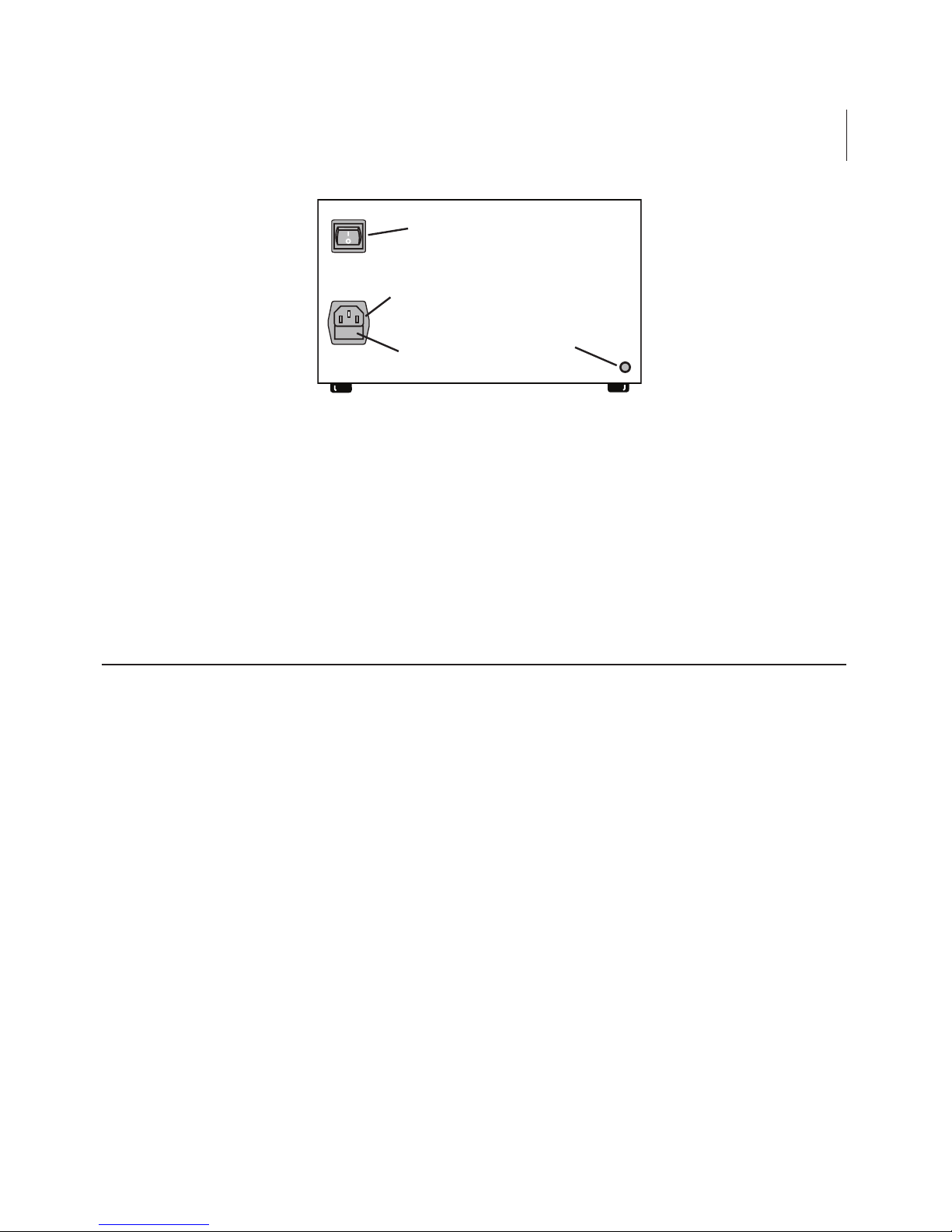
Electrical Considerations ........................... 1
Current Requirements ............................ 2
Fuse Replacement .................................. 2
Connecting Power ..................................... 3
System Overview ....................................... 3
Hardware Familiarization ....................... 3
Software Familiarization ......................... 5
Tube Routing ............................................. 6
Color Coding ......................................... 6
Connecting the Waste Removal System . . 8
Connecting the Wash System ................. 8
Inserting Tubing Into the Solenoid Valves. 9
Checking for Leaks ............................... 10
Using a Second Delivery Container ...... 10
Cleaning the Blot Washer After Use ......... 12
Cleaning Tubing and Containers ........... 12
Discarding Waste and Replacing Wash
Buffer ................................................... 13
Cleaning the Exterior Surface ............... 13
Chapter 2: Creating and Running
Programs
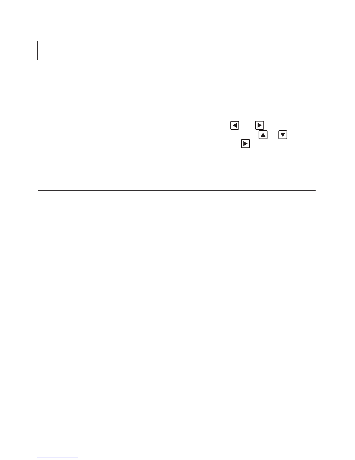
Keys You Should Be Familiar With ........... 15
Powering On the Blot Washer .................. 15
Selecting the Program Number to Edit
or Run ..................................................... 16
Editing a Program .................................... 16
Starting a Program ................................... 22
Pausing a Program ................................... 23
Stopping a Program ................................. 23
Using the Quad Harness .......................... 23
Scaling Up or Back .............................. 26
Default Program Descriptions .................. 26
Chapter 3: Calibration
Keys You Should Be Familiar With ........... 29
Checking System Pressure ....................... 30
Calibrating Dispense Volume ................... 30
Setting the Aspiration Vacuum Factor ....... 31
Chapter 4: Appendices
Accessory Part Numbers .......................... 33
Specifications .......................................... 33
Declaration of Conformity ....................... 35
Table of Contents


1
Chapter 1: System Familiarization
and Assembly
Placement in the Laboratory
Place the instrument away from sinks or other sources of water
that pose a shock hazard. Do not locate the Blot Washer where
the power cord will be walked on or exposed to water or chemical
spills.
Warning: Do not operate around flammable liquids or gases.
Electrical Considerations
For personal safety the Blot Washer must be properly grounded.
The power cords have a three-prong, grounded plug that mates
with a standard three-prong, grounded wall receptacle to minimize
the possibility of electric shock. The user should have the wall
receptacle and circuit checked by a qualified electrician to be
assured that the receptacle is properly grounded. Where a two-
prong receptacle is encountered, it is the responsibility of the user
to replace it with a properly grounded three-prong wall receptacle.
Warning: Do not under any circumstances, cut or remove the
third ground prong from the power cord. Do not use a two-prong
adapter plug.

2CHAPTER 1
System Familiarization and Assembly
Current Requirements
Current demand for the Blot Washer is modest, but it should be
added to other current demand on the circuit to make sure total
current demand does not exceed the rating of the fuse or circuit
breaker in use. Current demand for the various Blot Washer models
are listed below.
Caution: Be sure the line voltage is of the same value specified on
the nameplate located on the back panel.
Fuse Replacement
Warning: Before replacing a blown fuse, turn all switches to the
OFF position and unplug the instrument.
Figure 1 shows the location of the fuse in a small fuse drawer on
the back panel of the Blot Washer. A spare fuse is also located
in this drawer. Should the fuse blow, replace with a new fuse of
the same value. To remove a fuse, place the tip of a slot blade
screwdriver into the top of the fuse drawer and pry open.
Blot Washer Model Current Demand
115V < 0.5 Amps
230V < 0.25 Amps
Blot Washer Model Fuse Description
115V 5 mm x 20 mm, 500 mAmp
230V 5 mm x 20 mm, 250 mAmp

3
Power ON/OFF Switch
Fuse Drawer
Power Receptacle
Vacuum Inlet
Port
Blot Washer Back Panel
Connecting Power
Connect the power cord to the power receptacle on the Blot
Washer back panel and connect the power cord plug to a wall or
bench outlet.
System Overview
Hardware Familiarization
The Stovall Blot Washer is a straightforward liquid delivery and
aspiration instrument. An internal pump supplies positive pressure
for liquid delivery and house vacuum aspirates waste liquids from
blot containers. Air pressure from the internal pump is directed
through the blue pressure port located on the left side of the Blot
Washer (Figure 2). The vacuum inlet is located on the back panel
of the instrument (Figure 1) and the black vacuum outlet port is
beneath the blue air pressure port on the left side of the instrument
front panel.
Figure 1. Blot washer back panel showing location of the ON/OFF
power switch, power receptacle, fuse drawer, and vacuum port.

4
Vacuum Port
(black)
Pressure Port
(blue)
Aspiration
Valve Dispense
Valve #1 Dispense
Valve #2
Manual
Valve
Control
Buttons
Manifold
Green Indicator
Lights Signaling
Valve Open
Scroll keys to select
program functions
(edit programs,
calibration, etc.) LCD Display
Keys to increment/decrement
steps, dispense quantities, cyles,
timing, number of blots, etc.
Figure 2. Major components on the Blot Washer front panel.
CHAPTER 1
System Familiarization and Assembly
Software wash programs operate three solenoid valves to control
the flow of liquids. The normal condition of all valves is closed,
where by the flow of liquids is impeded by pinching the silicone
tubing closed. From left to right on the front panel (Figure 2) the
valves are:
• Aspiration Valve (larger) controls the aspiration of liquids to the
waste bottle.
• Dispense Valve #1 controls the delivery of wash buffer from the
large wash bottle.
• Dispense Valve #2 controls reagent delivery from the 140 ml
syringe or a second delivery reservoir.

5
During operation, the internal pump pressurizes the Wash Bottle
(Figure 3) through an air pressure line. When a new wash cycle
starts, Dispense Solenoid Valve #1 opens and the pressure in the
Wash Bottle dispenses wash buffer from the Wash Bottle to the blot
container.
The vacuum source is used to lower the air pressure in the
Waste Bottle. During a waste removal, the Aspiration Solenoid
Valve (Figure 2) opens and waste liquid is aspirated from the blot
container, and flows into the Waste Bottle.
When a wash program is configured, the user enters how many of
these dispense/aspiration cycles there are in a given wash step, how
much wash buffer is dispensed, and how long the liquid remains in
the blot container before aspiration.
Dispense Solenoid Valve #2 adds versatility by allowing a second
delivery container to be connected (Figure 5). Similar to the Wash
bottle, this second container is pressurized by the pump and liquid
is dispensed to the blot container when Dispense Solenoid Valve #2
is opened under program control. This second delivery container
can be used to dispense a second wash buffer or secondary
antibodies.
Each of the solenoid valves has a circular button above it. These
buttons manually open the solenoid valves and operate the valves
independently of programmed sequences. Manual control is most
commonly used when tubes are flushed during cleaning or during
calibration. When a solenoid valve is open, under program or
manual control, the indicator light above the manual control button
is illuminated.
Software Familiarization
Creating programs for a variety of wash sequences is described in
Chapter 2 and additional software functions for calibration are
discussed in Chapter 3. Before connecting tubing and filling

6CHAPTER 1
System Familiarization and Assembly
reservoir bottles, remove all port plugs, turn on the power switch,
and use the instructions in Chapters 2 and 3 to familiarize yourself
with the keypad and general software operation.
The most important keys to learn are the and keys for
navigation through menus and programs, and the or keys for
choosing options or changing numbers. The key is especially
important for navigation when editing programs. The other
three keys on the keypad are used to start, stop and pause wash
programs.
Tube Routing
The Blot Washer, reservoir bottles, and blot containers can be placed
in many different configurations depending on available lab space.
Lengths of supplied tubing are initially generous enough to accom-
modate different configurations. Once an optimal configuration has
been determined for your lab, you may want to shorten excessively
long tubes for a more organized, orderly appearance.
Figure 3 shows tubing connections for a standard configuration that
can be used to wash blots in one blot container. Tube routing is
shown for the wash bottle, waste bottle and vacuum source, Blot
Washer, and a single blot container connected to the Blot Washer
using the single dispensing harness.
Color Coding
Connectors on the wash bottle, waste bottle, and Blot Washer are all
color coded to facilitate making the correct connections.
Connecting each end of a tube to the same color connector will
lead to correct connections in most cases. The color codes have the
following meanings:
Black: vacuum source Orange: liquid waste
Blue: air pressure source Green: liquid dispensing

7
Figure 3. Standard tubing configuration for one delivery (wash)
bottle and one blot container. Connector color codes are shown.
Air Pressure Tubing
(Blue Luer Lock)
Wash Delivery Tubing
(Green Luer Lock)
Vacuum Tubing
(Black Luer Lock) Waste Tubing
(Orange Luer Lock)
Western Blot
Incubation Box
or Similar Blot
Container
Wash
Bottle
Waste
Bottle
Delivery
Tubing
Waste
Tubing
Blue
Black
ColletwithDelivery and
Aspiration Bits clipped
to the BlotContainer
Blot Washer Console

8CHAPTER 1
System Familiarization and Assembly
Connecting the Waste Removal System
Thick-walled, 1/4” i.d. tubing has been supplied for connecting a
house vacuum source to the black vacuum port (Figure 1) on the
back panel of the Blot Washer. Alternatively, this tubing can be
used to connect the Accessory Vacuum Pump.
The vacuum passes though the console and is available at the black
connector on the lower left side of the Blot Washer front panel
(Figure 2). Connect the black front panel vacuum connector to the
matching black connector on the Waste Bottle. Use the orange
connector to connect waste tubing from the Waste Bottle to the top
connector on the left side of the manifold (Figure 3). The waste
tubing should also be passed through the large Aspiration Solenoid
Valve. Insertion of tubing in solenoid valves is described later in
this chapter. Finally, the waste line is completed by connecting one
end of the single dispensing harness waste tube to the right side
connector on the manifold, and the other end to the aspiration bit
attached to the blot container. Make sure the bottom of the
aspiration bit touches the bottom of the blot container and the
beveled side of the aspiration bit faces the wall of the container.
(The aspiration bit suctions up the blot itself if the beveled side
points to the middle of the blot container.)
Connecting the Wash System
For best performance, place the Wash Bottle above the blot
container. Begin by connecting air delivery tubing from the blue
luer lock on the left side of the Blot Washer front panel (Figure 2) to
the blue luer lock connector on top of the Wash Bottle. Next
connect a wash delivery tube (smaller than the air delivery tubing)
from the green luer lock on top of the Wash Bottle to the middle
connector on the left side of the manifold (Figure 2). The wash
delivery tubing should pass through the Dispense Valve #1. Insertion
of tubing in solenoid valves is described below. Finally, the wash

9
delivery system is completed by connecting tubing from the single
dispensing harness to the right side connector on the manifold and
to the delivery bit in the blot container. The bottom of the delivery
bit should touch the bottom of the blot container.
Inserting Tubing Into the Solenoid Valves
The solenoid valves are closed until opened by manual or program
command. When placing the silicone tubing into a valve, or
extracting it from a valve, manually open the valve by pressing the
circular button above the valve as shown in Figure 4. Stretch the
tubing enough to slip it into the valve slot.
Manual open/close button for
Dispense Valve #1.
Figure 4. Tubing can be inserted in a solenoid valve by manually
opening the valve, stretching and inserting the tubing, then closing
the valve.
Position the tubing as needed by pulling it up or down, but only
while the valve is open. The indicator light for the valve is turned on
when the valve is open. When the tubing is positioned correctly,
close the valve by pressing the manual open/close button again.

10 CHAPTER 1
System Familiarization and Assembly
Checking for Leaks
After loading the containers with reagents in preparation for a run,
make sure all container lids are tight and luer lock connections are
secure. Chapter 3 describes a software function that indicates
whether the system is properly pressurized. Low pressure (< 20 kPa)
usually indicates a leak.
Using a Second Delivery Container
Figure 5 shows how to reconfigure the liquid delivery system for two
delivery containers. In Figure 5, the second delivery container is the
140 ml syringe, but it could also be a second wash bottle for a
configuration that delivers two different wash buffers. A typical
application for a second container is to deliver secondary
antibodies.
Notice that the air pressure provided by the Blot Washer’s pump is
divided with a “Y” connector in the tubing. The wash delivery tube
from the Wash Bottle is routed through Dispense Valve #1, as
before, but a second delivery tube from the syringe or second
container is routed through Dispense Valve #2 and connects to the
lower connector on the left side of the manifold. Connecting the
second delivery tube to the lower connector has the important
advantage of minimizing system contamination. When the wash
delivery tube is connected to the upper connector of the liquid
delivery part of the manifold, the inside of the manifold is cleaned
throughout the program.

11
Figure 5. Tubing configuration for using the 140 ml syringe or other
secondary delivery container (waste tubing not shown).
140 ml syringe or second
delivery container

12 CHAPTER 1
System Familiarization and Assembly
Cleaning the Blot Washer After Use
Cleaning Tubing and Containers
Cleaning of reagent containers and tubing is the primary mainte-
nance requirement. To eliminate almost all potential maintenance
problems, establish the habit of cleaning the Blot Washer immedi-
ately after use. Reagent residues are easy to clean up while they are
fresh and still wet. There are two adverse consequences of leaving
used reagents in the tubing for any length of time. The first is that
common antibody dilution buffers (BSA) are excellent substrates for
microbial growth. Second, over several days, microbial growth,
dried protein, or buffer crystals can form in the tubing, making
cleaning more difficult. The blot container should be clean for
every experiment.
For best performance, clean the delivery and waste tubing with
water immediately after each use. Disconnect the wash tubing from
the green luer lock on top of the wash bottle. Manually open the
dispense valve using the button above the valve and use a wash
bottle to flow water through the wash tubing. Close the dispense
valve when finished. The same procedure can be used to clean the
waste tubing connected to the orange luer lock on the top of the
waste bottle.
If you are running the same antibodies repeatedly, detergent
cleaning is necessary only occasionally. To completely prevent cross
contamination, residual protein/antibody in the lines can be cleared
with standard laboratory detergent solutions (e.g. 0.5% Sparkleen,
Nalgene L900 liquid cleaning solution) or with 0.5% sodium
dodecyl sulphate (SDS), followed by water. Replace old or damaged
tubing with new silicone tubing. If your programs contain only wash

13
steps (see Chapter 2) with buffers that do not contain protein,
detergent cleaning is not necessary unless the Blot Washer is not
going to be used for long periods of time (> 1 week).
Discarding Waste and Replacing Wash Buffer
Discarding Waste: Release the vacuum in the Waste Bottle by
unscrewing the two luer locks that connect the tubing to the top of
the bottle. Take the top off. Discard the waste. Replace the top and
reconnect the tubing, observing the color coding — connect black
to black and orange to orange.
Replacing Wash Buffer: Unscrew the two luer locks that connect
the tubing to the top of the bottle. Take the top off. Replace the buf-
fer. Occasionally, you should wash out the buffer bottle after many
repeated uses, or if a different buffer is to be used. Replace the top
and reconnect the tubing, observing the color coding — connect
green to green and blue to blue.
Cleaning the Exterior Surface
Warning: Always unplug the power cord from the receptacle before
cleaning the Blot Washer.
Warning: Do not immerse the Blot Washer in water or other liquid.
The exterior of the Blot Washer can be cleaned with a rag dampened
with a solution of mild detergent. Rinse by wiping with a cloth
dampened in water. Do not use scouring compounds, solvents such
as acetone, benzene, carbon tetrachlorides, lacquer thinner, or
alcohol to clean the exterior surfaces.


15
Chapter 2: Creating and Running
Programs
Up to 20 programs, numbered 1 through 20, can be stored in the
Blot Washer memory. With 1 to 4 individually configurable steps
per program, Blot Washer has the flexibility to accomplish any typi-
cal blot washing task. Initially, each of the 20 programs are prepro-
grammed at the factory as described at the end of this section. As
you create your own programs, you may want to develop a system
to document each program for easy recall.
Keys You Should Be Familiar With
Most of the keystrokes in creating a program are used to toggle be-
tween available options for a program step, or to accept the current
option and move to the next step.
or – Toggles through available options for a step.
– Accepts the current option and moves to the next step.
Powering On the Blot Washer
1) Turn on the power switch on the back of the Blot Washer control
console.
SELECT NUMBER OF
BLOTS: SINGLE
The initial display is used to select
the number of blots.

16 CHAPTER 2
Creating Wash Sequences
“Single” is always the correct choice unless the Quad Harness is
being used. See Using the Quad Harness below to learn how to
enter programs for washing 1 to 4 blots simultaneously.
Selecting the Program Number to Edit or Run
2) Press to accept “Single” for the number of blots.
Three actions are possible when this display is shown:
a) Press or to change the program number to any of the
20 programs.
b) Press to run the specified program (see Starting a Program
below).
c) Press to edit the specified program as described below.
Editing a Program
In this example, you’ll make a few changes to program #1.
3) With program number 1 still displayed, press to edit the
program.
EDIT PROGRAM 1
SELECT STEPS: 4
The and keys change the
number of steps.
SELECT PROGRAM
NUMBER: 1
Table of contents
Other SLS Laboratory Equipment manuals
Popular Laboratory Equipment manuals by other brands

Velp Scientifica
Velp Scientifica BOD Sensor F102B0133 instruction manual

Teledyne
Teledyne AutoInjector Module Installation and operation guide

Jeio tech
Jeio tech OV-11 Service manual

Sonation
Sonation USBB-S user manual

GenScript
GenScript eStain L1 instructions

Swan Analytical Instruments
Swan Analytical Instruments AMI Turbiwell Operator's manual