manuals.online logo
Brands
  1. Home
  2. •
  3. Brands
  4. •
  5. Dossena
  6. •
  7. Relay
  8. •
  9. Dossena DER3/1DL User manual

Dossena DER3/1DL User manual

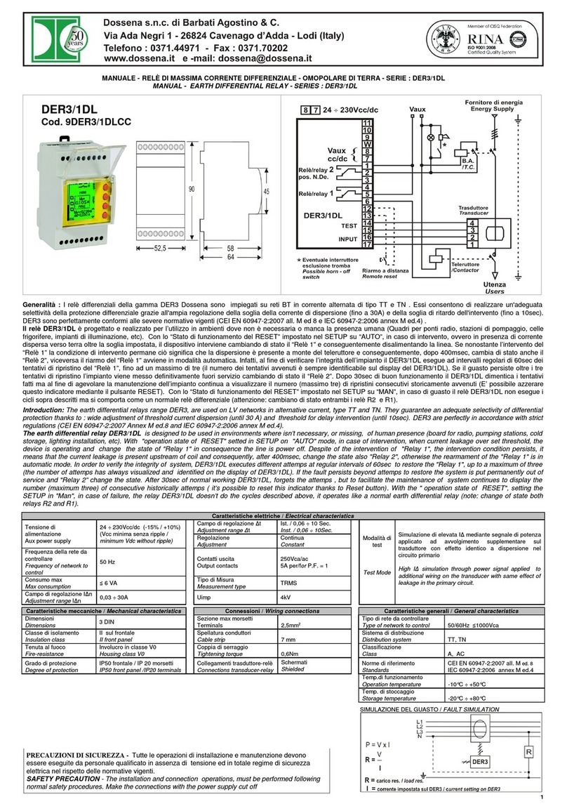
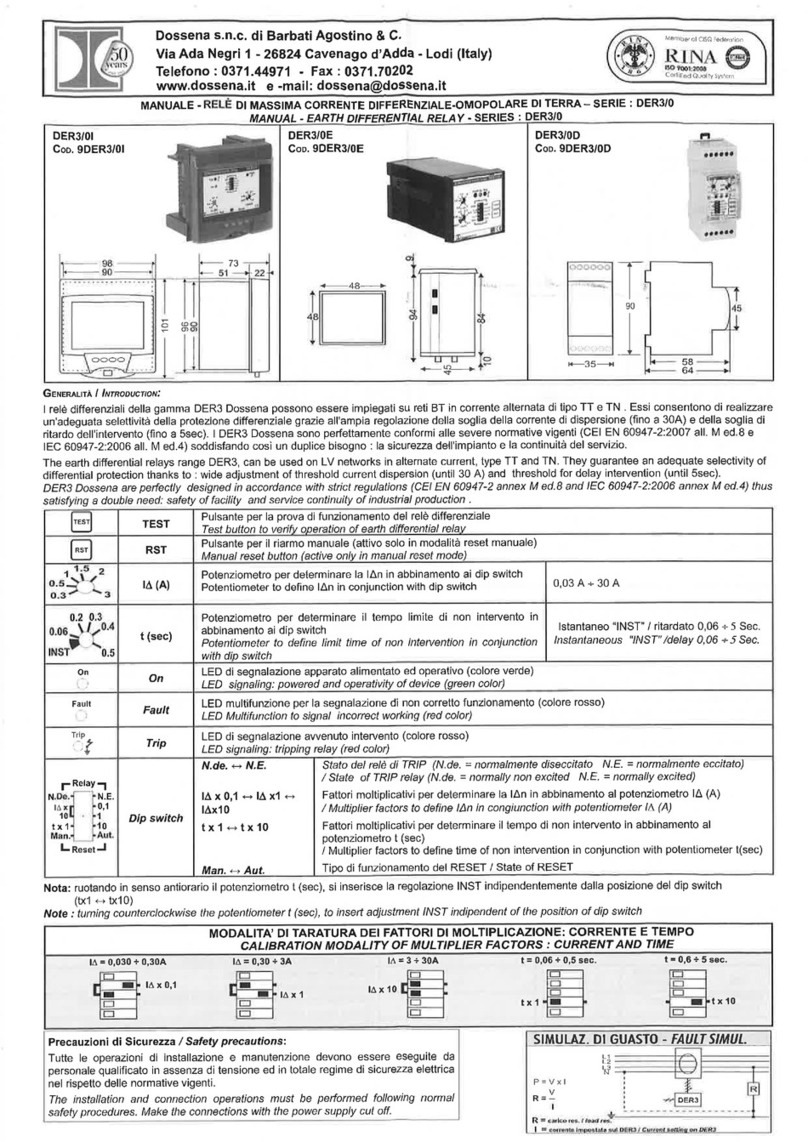
MANUALE - RELÈ DI MASSIMA CORRENTE DIFFERENZIALE - OMOPOLARE DI TERRA - SERIE : DER3/1DL
MANUAL - EARTH DIFFERENTIAL RELAY - SERIES : DER3/1DL
Generalit : I relè differenziali della gamma DER3 Dossena sono impiegati su reti BT in corrente alternata di tipo TT e TN . Essi consentono di realizzare un'adeguata
selettività della protezione differenziale grazie all'ampia regolazione della soglia della corrente di dispersione fino a 30A) e della soglia di ritardo dell'intervento fino a 10sec).
DER3 sono perfettamente conformi alle severe normative vigenti CEI EN 60947-2:2007 all. M ed 8 e IEC 60947-2:2006 annex M ed.4) .
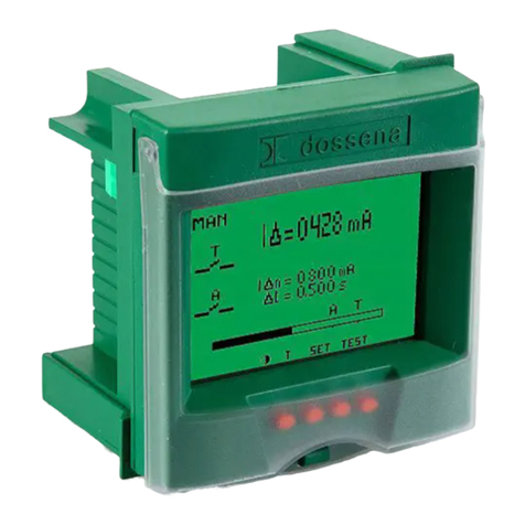
Il relè DER3/1DL è progettato e realizzato per l’utilizzo in ambienti dove non è necessaria o manca la presenza umana Quadri per ponti radio, stazioni di pompaggio, celle
frigorifere, impianti di illuminazione, etc). Con lo “Stato di funzionamento del RESET” impostato nel SETUP su “AUTO”, in caso di intervento, ovvero in presenza di corrente
dispersa verso terra oltre la soglia impostata, il dispositivo interviene cambiando di stato il “Relè 1” e conseguentemente disalimentando la linea. Se nonostante l’intervento del
“Relè 1” la condizione di intervento permane ciò significa che la dispersione è presente a monte del teleruttore e conseguentemente, dopo 400msec, cambia di stato anche il
“Relè 2”, viceversa il riarmo del “Relè 1” avviene in modalità automatica. Infatti, al fine di verificare l’integrità dell’impianto il DER3/1DL esegue ad intervalli regolari di 60sec dei
tentativi di ripristino del “Relè 1”, fino ad un massimo di tre il numero dei tentativi avvenuti è sempre identificabile sul display del DER3/1DL). Se il guasto persiste oltre i tre
tentativi di ripristino l’impianto viene messo definitivamente fuori servizio cambiando di stato il “Relè 2”. Dopo 30sec di buon funzionamento il DER3/1DL dimentica i tentativi
fatti ma al fine di agevolare la manutenzione dell’impianto continua a visualizzare il numero massimo tre) di ripristini consecutivi storicamente avvenuti E’ possibile azzerare
questo indicatore mediante il pulsante RESET). Con lo “Stato di funzionamento del RESET” impostato nel SETUP su “MAN”, in caso di guasto il relè DER3/1DL non esegue i
cicli sopra descritti ma si comporta come un normale relè differenziale attenzione: cambiano di stato entrambi i relè R2 e R1).
Introduction: The earth differential relays range DER3, are used on LV networks in alternative current, type TT and TN. They guarantee an ade uate selectivity of differential
protection thanks to : wide adjustment of threshold current dispersion (until 30 A) and threshold for delay intervention (until 10sec). DER3 are perfectly in accordance with strict
regulations (CEI EN 60947-2:2007 Annex M ed.8 and IEC 60947-2:2006 annex M ed.4).
The earth di erential relay DER3/1DL is designed to be used in environments where isn’t necessary, or missing, of human presence (board for radio, pumping stations, cold
storage, lighting installation, etc). With "operation state of RESET" setted in SETUP on "AUTO" mode, in case of intervention, when current leakage over set threshold, the
device is operating and change the state of "Relay 1" in conse uence the line is power off. Despite of the intervention of "Relay 1", the intervention condition persists, it
means that the current leakage is present upstream of coil and conse uently, after 400msec, change the state also "Relay 2", otherwise the rearmament of the "Relay 1" is in
automatic mode. In order to verify the integrity of system, DER3/1DL executes different attemps at regular intervals of 60sec to restore the "Relay 1", up to a maximum of three
(the number of attemps has always visualized and identified on the display of DER3/1DL). If the fault persists beyond attemps to restore the system is put permanently out of
service and "Relay 2” change the state. After 30sec of normal working DER3/1DL, forgets the attemps , but to facilitate the maintenance of system continues to display the
number (maximum three) of consecutive historically attemps ( it’s possible to reset this indicator thanks to Reset button). With the " operation state of RESET", setting the
SETUP in "Man", in case of failure, the relay DER3/1DL doesn’t do the cycles described above, it operates like a normal earth differential relay (note: change of state both
relays R2 and R1).
Caratteristiche elettriche / Electrical characteristics
Tensione di
alimentazione
Aux power supply
48 ÷ 400Vca/ac -15% / +10%)
Campo di regolazione Δt
Adjustment range Δt
Ist. / 0,06 ÷ 10 Sec.
Inst. / 0,06 ÷ 10Sec.
Regolazione
Adjustment
Continua
Constant
Frequenza Vaux
Vaux Fre uency 50/60Hz Contatti uscita
Output contacts
250Vca/ac
5A per/for P.F. = 1
Consumo max
Max consumption ≤ 6 VA Tipo di Misura
Measurement type TRMS
Campo di regolazione IΔn
Adjustment range IΔn 0,03 ÷ 30A Uimp 4kV
Modalità di
test
Test Mode
Simulazione di elevata IΔ mediante segnale di potenza
applicato ad avvolgimento supplementare sul
trasduttore con effetto identico a dispersione nel
circuito primario
High IΔ simulation through power signal applied to
additional wiring on the transducer with same effect of
leakage in the primary circuit.
Caratteristiche meccaniche / Mechanical characteristics Connessioni / Wiring connections Caratteristiche generali / General characteristics
Dimensioni
Dimensions 3 DIN Sezione max morsetti
Terminals 2,5mm2
Tipo di rete da controllare
Type of network to control 50Hz ≤1000Vca
Classe di isolamento
Insulation class
II sul frontale
II front panel
Spellatura conduttori
Cable strip 7 mm
Sistema di distribuzione
Distribution system TT, TN
Tenuta al fuoco
Fire-resistance
Involucro in classe V0
Housing class V0
Coppia di serraggio
Tightening tor ue 0,6Nm
Classificazione
Class A, AC
Grado di protezione
Degree of protection
IP50 frontale / IP 20 morsetti
IP50 front panel /IP20 terminals
Collegamenti trasduttore-relè
Connections transducer-relay
Schermati
Shielded
Norme di riferimento
Standards
CEI EN 60947-2:2007 all. M ed. 8
IEC 60947-2:2006 annex M ed.4
Temp.di funzionamento
Operation temperature -10°C ÷ +50°C
Temp. di stoccaggio
Storage temperature -20°C ÷ +80°C
PRECAUZIONI DI SICUREZZA - Tutte le operazioni di installazione e manutenzione devono
essere eseguite da personale qualificato in assenza di tensione ed in totale regime di sicurezza
elettrica nel rispetto delle normative vigenti.
SAFETY PRECAUTION - The installation and connection operations, must be performed following
normal safety procedures. Make the connections with the power supply cut off
1
DER3/1DL
Cod. 9DER3/1DL
SIMULAZIONE DEL GUASTO / FAULT SIMULATION
CONSIGLI DI INSTALLAZIONE / INSTALLATION SUGGESTIONS
1) Prima di alimentare l’apparecchiatura DER3 verificare di aver eseguito correttamente tutti i collegamenti necessari
2) La sezione dei conduttori deve essere tale che la resistenza totale delle connessioni DER3↔ trasduttore andata+ritorno) non superi 1Ω
3) Ridurre al minimo la distanza dei collegamenti tra DER3 e trasduttore separare il circuito di misura da quello di prova) tenendoli il più lontano possibile da cavi di potenza;
utilizzare cavi schermati con lo schermo isolato dai conduttori interni e connesso a terra in un solo punto.
1) Before powered the DER3, verifies that all connections have been executed correctly
2) Conductors size has to consider that total resistance of connections between DER3↔transducer and vice versa don’t exceed 1Ω
3) Reduce to the minimum the distance between DER3 and transducer, separate the measure circuit from test circuit and keep them away from power cable, use shielded
wires with insulated conductors and connect to ground in only one point.
Con igurazione - SET UP
Display azzurro / Blue display Funzione dei pulsanti / keys unction
TEST = pulsante di test
SET = 1 premere per almeno 3 secondi per entrare nel SET UP
2 premere per visualizzare i parametri in modo ciclico
3 premere per almeno 3 secondi per uscire dal SET UP e salvare i parametri
impostati il display ritorna verde); in alternativa dopo circa 3 minuti ed in modo automatico
il DER3 esce dal SET UP senza salvare le modifiche
TEST = test button
SET = 1 push or at least 3 seconds to enter in SET UP
2 push to see the parameters in cyclic
3 push or at least 3 seconds to exit rom SETUP and save the parameters (display
return green); in alternative, after 3 minutes, in automatic mode, the DER3 exits from SET
UP without saving
▲▼ = premere per modificare il parametro selezionato
push to modify the selected parameter
Note: in caso di Allarme/Trip, durante l'operazione di SETUP, il DER3 interverrà secondo le impostazioni del precedente SETUP. Per visualizzare la causa di Allarme/Trip,
uscire dal SETUP.
Note: in case of Alarm/Trip, during SETUP operations, DER3 will operate in according to previous SETUP. To display cause of Alarm/Trip exit from SETUP.
TABELLA 1 / TABLE 1
PREDISPOSIZIONE PARAMETRI
SET UP PARAMETERS
CAMPO DI REGOLAZIONE
ADJUSTMENT RANGE
VALORI DI DEFAULT
DEFAULT VALUES
Stato del relè R2 N.De. N.E.
State of R2
N.De. norm. diseccitato / N.E. norm. eccitato sicurezza positiva)
N.De normally not-excited / N.E. normally excited (positive security)
N.De.
Stato di funzionamento del reset
State of reset
Manuale “MAN.” / automatico “AUTO”
Manual “MAN.” / automatic “AUTO”
MAN
KCT = rapporto di trasformazione del trasduttore
KCT = transformation ratio of transducer
0,001 ÷ 30 K (K = x1000) 0,500K
Soglia della corrente differenziale nominale d'intervento I∆n (Α)
Nominal current threshold of intervention I
∆
n
(Α)
0,03 A ÷ 30 A 30A
Tempo limite di non intervento ∆t s)
Time limit of non intervention
∆
t (s)
Istantaneo “INST” / ritardato 0,06 ÷ 10 s
Instantaneous “INST” / delay 0,06
÷ 10
s
0,5 s
Stato del relè R2 : con il simbolo il relè è normalmente diseccitato N.De.) e si eccita quando la I∆ supera la I∆n.
con il simbolo il relè è normalmente eccitato N.E.) e si diseccita quando la I∆ supera la I∆n. sul display appare la scritta NE)
Attenzione: la condizione di sicurezza positiva) N.E. è applicata solo ed esclusivamente al relè R2. L'impostazione della sicurezza positiva esclude il test continuo di verifica
del circuito della bobina di apertura B.A. e della sua alimentazione.
State o R2 : with the symbol the relay is normally de-energized (N.De.) and it energizes when I
∆
overcome I
∆
n
with the symbol the relay is normally energized (N.E.) and it de-energizes when I
∆
overcome I
∆
n (on display appears the write NE)
Warning : N.E., safety condition, is applied exclusively to the R2 relay and not to second relay even it setted in TRIP condition. Setting the positive security excludes the
permanent verification of the circuit of opening coil T.C. and its supply.
Stato di funzionamento del Reset : il reset può essere impostato come manuale sul display compare la scritta MAN) o come automatico compare la scritta AUTO). In
modalità manuale, a seguito di uno scatto per IΔ>IΔn, la scritta “SET” accanto al pulsante relativo, diventa “RESET” e quel pulsante permetterà quindi il RESET nella
condizione di TRIP. Nella modalità “AUTO” si realizza il funzionamento descritto nelle generalità.
State o Reset : the reset can be set to manual (on the display appears the word MAN) or automatic mode (appears word AUTO). In manual mode, when IΔ>IΔn, the word SET
become RESET, this button allows to reset the TRIP condition. In “AUTO” mode it operates as described in introduction.
KCT = il rapporto di trasformazione di default del trasduttore della “serie D” è 0,500 K K significa x 1000); modificare solo se si usano i trasduttori D80S e D300M
KCT = the default transformation ratio of transducer "Series D" is 0.500 K (K means x 1000); modify only with the use of transducers D80S and D300M.
Soglia della corrente di dispersione nominale I∆n (A) : valore al quale la I∆ provoca l'intervento del relè per comandare l'apertura dei circuiti di potenza
Nominal current threshold o intervention I∆n
(Α)
: the value at which the IΔ causes the intervention of TRIP relay to control the opening of power circuits.
Tempo limite di non intervento : ritardo entro il quale una corrente differenziale più elevata di IΔn può fluire nel DER3 senza provocare l'intervento; il campo di regolazione è
compreso tra istantaneo INST) e 10 secondi.
Time limit o non intervention : delay during which a residual current higher than IΔn can flow into DER3 wout cause intrervention. The adjustment range is between
INST and 10s.
2
VIGILANZA / VIGILANCE
STATO DI NORMALE VIGILANZA / NORMAL VIGILANCE
Display verde / Green display
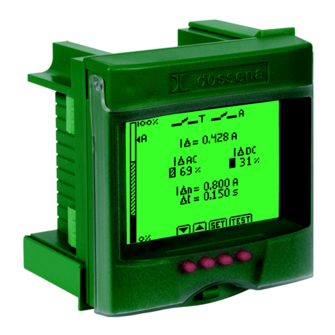
Misure e parametri /
Measures and parameters
I∆ = corrente di dispersione in tempo reale trms)
/leakage current in real time (trms)
I∆n = soglia corrente di dispersione nominale
/nominal current threshold of leakage
∆t = tempo limite di non intervento
/time limit of non intervention
Istogramma = rappresenta la misura della corrente
I∆ espressa in % di IΔn
Histogram = represents the measurement of current
I∆ % expressed of IΔn
TENTATIVI DI RIPRISTINO / ATTEMPTS TO RESTORE
TENTATIVO 1 / ATTEMPT 1 EVENTI / EVENTS
display lampeggiante giallo/rosso
/ flashing display yellow/red
relè R2 non cambia stato, relè R1cambia stato
/ relay R2 not change state, relay R1 change state
lampeggia il segnale di pericolo
/ flashing danger signal
lampeggia la scritta TRY 1
/ flashing write TRY 1
si annerisce l'icona simbolo del primo tentativo TRY 1
/ blackens the icon symbol of the first attempt TRY 1
appare la scritta RESET per resettare i ripristini consecutivi storicamente avvenuti
/ appears the write RESET to reset the consecutive historically attemps
TENTATIVO 2 / ATTEMPT 2 EVENTI / EVENTS
display lampeggiante giallo/rosso
/ flashing display yellow/red
relè R2 non cambia stato, relay R1cambia stato
/ relay R2 not change state, relè R1 change state
lampeggia il segnale di pericolo
/ flashing danger signal
lampeggia la scritta TRY 2
/ flashing write TRY 2
si anneriscono le icone simbolo del secondo tentativo “TRY 2”
/ blackens the icons symbol of the second attempt “TRY 2”
appare la scritta RESET per resettare i ripristini consecutivi storicamente avvenuti
/ appears the write RESET to reset the consecutive historically attemps
TENTATIVO 3 / ATTEMPT 3 EVENTI / EVENTS
display lampeggiante giallo/rosso
/ flashing display yellow/red
relè R2 non cambia stato, relè R1cambia stato
/ relay R2 not change state, relay R1 change state
lampeggia il segnale di pericolo
/ flashing danger signal
lampeggia la scritta TRY 3
/ flashing write TRY 3
si anneriscono le icone simbolo del terzo tentativo “TRY 3”
/ blackens the icons symbol of the third attempt “TRY 3”
appare la scritta RESET per resettare i ripristini consecutivi storicamente avvenuti
/ appears the write RESET to reset the consecutive historically attemps
TRIP (R2) EVENTI / EVENTS
display rosso fisso
/ display is lighting red
relè R2 cambia stato, relè R1cambia stato
/ relay R2 change state, relay R1 change state
lampeggia il segnale di pericolo
/ flashing danger signal
lampeggia la scritta “TRIP”
/ flashing write TRIP
appare la scritta RESET per resettare la condizione di TRIP
/ appears the write RESET to reset the TRIP condition
Note: Dopo 30sec di buon funzionamento il DER3/1DL dimentica i tentativi fatti ma al fine di agevolare la manutenzione dell’impianto continua a visualizzare il numero
massimo tre) di ripristini consecutivi storicamente avvenuti è possibile azzerare questo indicatore mediante il pulsante RESET). Il display è di colore verde.
After 30sec of normal working DER3/1DL ,forgets the attemps , but to facilitate the maintenance of system continues to display the number (maximum three) of
consecutive historically attemps (it’s possible to reset this indicator pressing RESET button).The display is green.
3
TEST
Il test verifica l'intero sistema di protezione differenziale DER3 + Trasduttore + B.A.) / the test checks the complete differential protection system (DER3 + T.+ T.C.)
Modalit / Modality Eventi / Events
Modalità “MAN”
“MAN” mode
display rosso fisso / display is lighting red
relè R2 e relè R1 cambiano stato
/ relay R2 and R1 relay change state
lampeggia il segnale di pericolo
/ flashing danger signal
lampeggia la scritta “TRIP”
/ flashing write TRIP
Funzione dei pulsanti / Keys unction
TEST = premere per eseguire il test
/push test button to perform the test
RESET = premere per riarmare il relè differenziale e
riportarlo in condizione di normale vigilanza
RESET = push to perform the riarmament and
return in normal vigilance
Modalità “AUTO”
“AUTO” mode
Premendo una volta il test si simula una dispersione di corrente differenziale in impianto), si verifica la
condizione “ tentativo 1” con un icona ■ annerita, dopo 60” il display si riporta in modalità vigilanza verde),
se si preme nuovamente il test, si verifica la condizione “ tentativo 2” con due icone ■■ annerite, dopo 60” il
display si riporta in modalità vigilanza verde), se si preme nuovamente il test, si verifica la condizione “
tentativo 3” con tre icone ■■■ annerite, dopo 60” il display si riporta in modalità vigilanza verde), se si
preme nuovamente il test, si verifica la condizione di TRIP che tramite la B.A. provoca l'apertura definitiva
dei circuiti di potenza.
Pushing once, the test button (it simulates the differential current leakage in the system), it verifies the
condition “attemp 1” with icon ■ (blacken), after 60'' the display backs in surveillance mode (green). If you
push again the test button it's possible to verify the condition “attemp 2” with two icons ■■ (blaken), after 60''
the display backs to normal surveillance (green). If you push again the test button it's possible to verify the
condition “attemp 3” with ■■■ icons (blaken), after 60'' the display backs in normal surveillance (green). If
you push again the test button it's possible to verify trip condition by opening coil that causes the opening of
power circuit.
ALLARME/ ALARM
ALLARME B.A. / B.A. ALARM
(solo per “R2” normalmente diseccitato in entrambe le modalità “MAN e “AUTO”) / ( only for “R2” normally de-energized in both modality “MAN” and “AUTO”)
Eventi / Events
display lampeggiante giallo/rosso / flashing display yellow/red
relè R1 cambia stato. / R1 relay change state
lampeggia il segnale di pericolo / flashing danger signal
lampeggia la scritta BA / flashing write BA
Causa / Cause
Può essere accaduto che:
-sia avvenuta una interruzione nell'avvolgimento della B.A.
-sia avvenuta una disconnessione tra DER3 e B.A.
-sia venuta a mancare la tensione che a seguito del TRIP permetterebbe
l'azionamento della B.A.
It is detected : the stop winding of T.C., the disconnection between DER3 and T.C.,
the lack of power supply voltage that compromise the operation of T.C.
ALLARME DI TRIP (I∆n) / TRIP ALARM (I
∆
n)
Eventi / Events
display rosso fisso / display lighting red
relè R1 cambia stato. / R1 relay change state
relè R2 cambia stato / relay R2 change state
lampeggia il segnale di pericolo / flashing danger signal
lampeggia la scritta TRIP / flashing write TRIP
incremento dell'istogramma / increase histogram
memorizzazione e visualizzazione del valore di corrente per cui è avvenuto l'intervento /
storage and display of current value for which the intervention occurred
Causa / Cause
- la corrente di dispersione I∆ ha superato almeno l'85% della soglia preimpostata
come I∆n e persiste per almeno 400ms dopo l'intervento del relè R1. / the leakage
current I
∆
 has exceeded at least 85% of preset threshold as I
∆
n and persists for at
least 400ms after the R1 relay.
- in modalità “AUTO” se una volta raggiunto lo stato “TRY3” si verifica un nuovo
superamento della soglia / In “AUTO” mode only if after “TRY3” there is a new
exceeding of threshold
ALLARME TRASDUTTORE /TRANSDUCER ALARM
Eventi / Events
display rosso fisso / display lighting red
relè R1 cambia stato. / R1relay change state
relè R2 cambia stato / relay R2 change state
lampeggia il segnale di pericolo / flashing danger signal
lampeggia la scritta TORO / flashing write TORO
Causa / Cause
Può essere accaduto che:
- si sia staccata una delle 4 connessioni tra DER3 e trasduttore
- si sia interrotto uno dei due avvolgimenti interni al trasduttore
- si sia verificato un cortocircuito nei suddetti avvolgimenti o nelle connessioni
It is detected: the disconnection one of four connections between DER3 and
tranducer, the interruptions one of two internal windings to transducer, the short
circuits on windings or connections
ALLARME TEMPERATURA / TEMPERATURE ALARM
Eventi / Events
display rosso fisso / display lighting red
relè R2 cambia stato / relay R2 change state
lampeggia il segnale di pericolo / flashing danger signal
lampeggia la scritta TEMP / flashing write TEMP
Causa / Cause
Il sensore di rilevamento della temperatura interna registra un valore oltre la soglia
del normale funzionamento; la condizione persiste fino a che la temperatura si
riporta sotto la soglia.
The sensor detecting the temperature inside record value beyond normal
threshold, the condition persists until the temperature
ERRATA ALIMENTAZIONE / WRONG SUPPLY
Eventi / Events
display rosso fisso / display lighting red
appare il logo e scritta dossena / appears logo and write dossena
appare il segnale di pericolo / appears danger signal
appare la scritta WRONG SUPPLY / appears WRONG SUPPLY
Causa / Cause
Il DER3 rileva un errata alimentazione e tutte le funzioni sono inibite
The DER3 detects an incorrect Vaux and all functions are inhibited
Note: A seguito di forti ed anomale sollecitazioni elettromagnetiche potrebbe accadere che sul display scompaia la simbologia; in tale caso premere semplicemente uno dei
tasti ▲ ▼ per ritornare alla normale visualizzazione.
Note: Following strong electromagnetic deviations could happen that on display the simbology desappears ; in this case push one of the buttons ▲ ▼ to return on normal
display.
MU 1155 Rev. 0.1 04/06/12
4

This manual suits for next models

1

Other Dossena Relay manuals

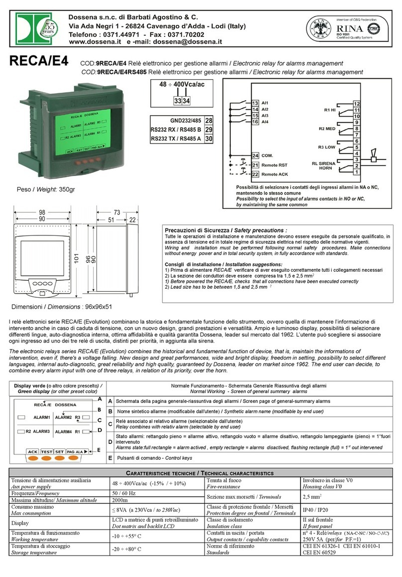
Dossena RECA/E4 User manual

Dossena

Dossena RECA/E4 User manual

Dossena DER3/0 Series User manual

Dossena

Dossena DER3/0 Series User manual

Dossena SRI3/D2 User manual

Dossena

Dossena SRI3/D2 User manual

Dossena DER3B-MED Series User manual

Dossena

Dossena DER3B-MED Series User manual

Dossena RECA/E8 User manual

Dossena

Dossena RECA/E8 User manual

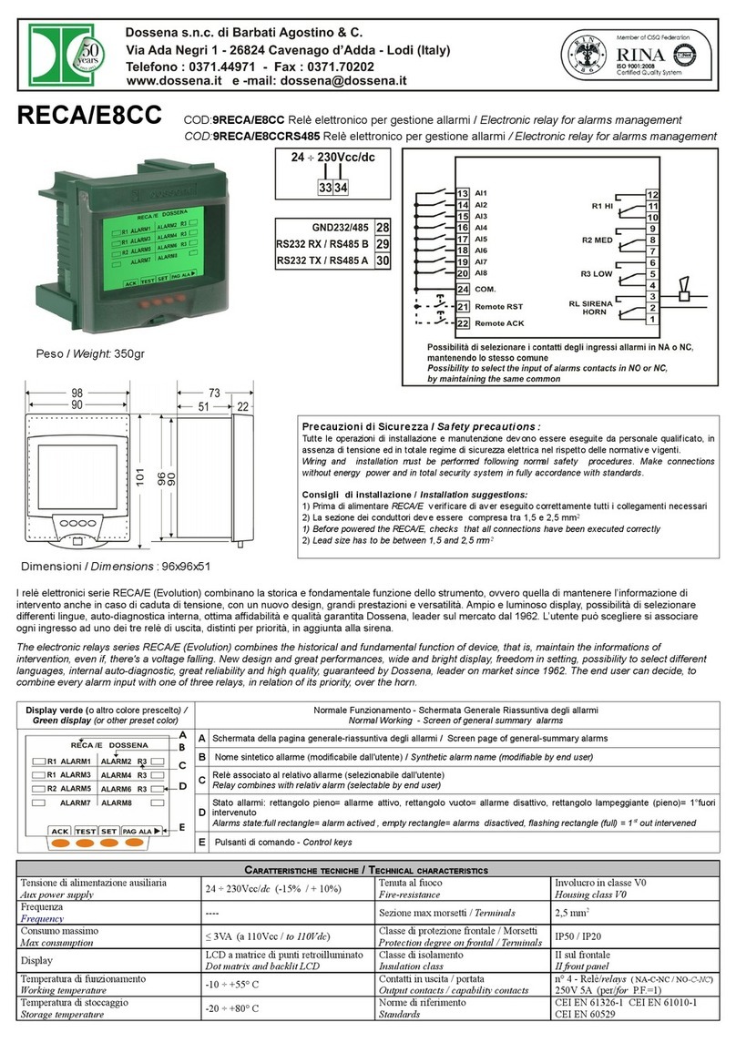
Dossena RECA/E8CC User manual

Dossena

Dossena RECA/E8CC User manual

Dossena DER3/0 Series User manual

Dossena

Dossena DER3/0 Series User manual

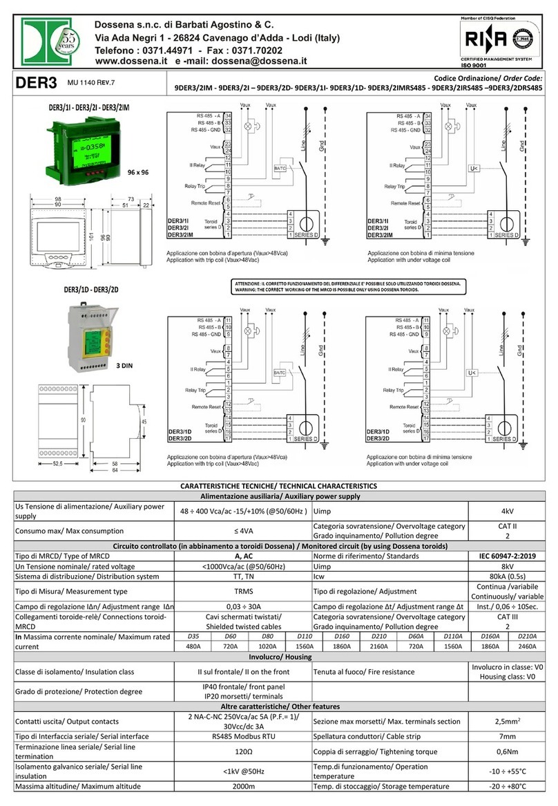
Dossena DER3 User manual

Dossena

Dossena DER3 User manual

Dossena SRI3/H2 User manual

Dossena

Dossena SRI3/H2 User manual

Dossena DER3B-DUAL Series User manual

Dossena

Dossena DER3B-DUAL Series User manual

Dossena 9DER3/1DLCC User manual

Dossena

Dossena 9DER3/1DLCC User manual

Dossena SRI3/I2 User manual

Dossena

Dossena SRI3/I2 User manual

Dossena 9DER3/2IM User manual

Dossena

Dossena 9DER3/2IM User manual

Dossena RECA/E4CC User manual

Dossena

Dossena RECA/E4CC User manual

Dossena DER3 User manual

Dossena

Dossena DER3 User manual

Dossena DER3BDUAL User manual

Dossena

Dossena DER3BDUAL User manual

Popular Relay manuals by other brands

GE CEY53A instructions

GE

GE CEY53A instructions

Data Industrial 330 owner's manual

Data Industrial

Data Industrial 330 owner's manual

Rockwell Automation Allen-Bradley Guardmaster DI user manual

Rockwell Automation

Rockwell Automation Allen-Bradley Guardmaster DI user manual

GE IFC53M instructions

GE

GE IFC53M instructions

GE SLYG81A instructions

GE

GE SLYG81A instructions

Videx VX8900 manual

Videx

Videx VX8900 manual

Eaton EMR-3MP0 Installation, operation and maintenance

Eaton

Eaton EMR-3MP0 Installation, operation and maintenance

Westinghouse KAB Installation, operation & maintenance instructions

Westinghouse

Westinghouse KAB Installation, operation & maintenance instructions

gefran GT 25 manual

gefran

gefran GT 25 manual

Honeywell X47 installation guide

Honeywell

Honeywell X47 installation guide

TIS ACM-2R-2Z installation manual

TIS

TIS ACM-2R-2Z installation manual

IME Iso D4Z manual

IME

IME Iso D4Z manual

FANOX SIA C Series Installation & commissioning guide

FANOX

FANOX SIA C Series Installation & commissioning guide

Siemens 7SR46 Argus Quick reference guide

Siemens

Siemens 7SR46 Argus Quick reference guide

KMC Controls FlexStat BAC-12xx36 Series installation guide

KMC Controls

KMC Controls FlexStat BAC-12xx36 Series installation guide

Leviton EZ-Max Plus Programming guide

Leviton

Leviton EZ-Max Plus Programming guide

GE GEH-6432 user guide

GE

GE GEH-6432 user guide

F&F PK-2Z-LED 24 V manual

F&F

F&F PK-2Z-LED 24 V manual

manuals.online logo
manuals.online logoBrands
  • About & Mission
  • Contact us
  • Privacy Policy
  • Terms and Conditions

Copyright 2025 Manuals.Online. All Rights Reserved.