www.ti.com
2SLUUBH5–November 2016
Submit Documentation Feedback
Copyright © 2016, Texas Instruments Incorporated
Using the Stacking TPS546C23 Two Phase Evaluation Module
3 Tip and Barrel Measurement............................................................................................... 8
4 Efficiency of 1.2-V Output vs Line and Load ........................................................................... 14
5 Load Regulation of 1.2-V Output......................................................................................... 14
6 Line Regulation of 1.2-V Output (Different Board)..................................................................... 15
7 Transient Response of 1.2-V Output at 12 VIN, Transient is 10 A to 60 A, 0.2 A/µs .............................. 15
8 Output Ripple and SW Node of 1.2-V Output at 12 VIN, 0-A Output................................................. 16
9 Output Ripple and SW Node of 1.2-V Output at 12 VIN, 70-A Output .............................................. 16
10 Start up from Control, 1.2-V Output at 12 VIN, 0-A Output (TON_RISE is modified to 5ms) ..................... 17
11 Start up from Control, 1.2-V Output at 12 VIN, 70-A Output (TON_RISE is modified to 5ms).................... 17
12 Soft Stop from Control, 1.2-V Output at 12 VIN, 0-A Output (TON_RISE is modified to 5ms) ................... 18
13 Soft Stop from Control, 1.2-V Output at 12 VIN, 70-A Output (TON_RISE is modified to 5ms).................. 18
14 Inductor Current and Switch Node Waveform, 1.2-V Output at 12 VIN, 70-A Output.............................. 19
15 Bode Plot at 1.2-V Output at 12 VIN, 0-A Output ...................................................................... 19
16 Bode Plot at 1.2-V Output at 12 VIN, 70-A Output...................................................................... 20
17 Thermal Image ............................................................................................................. 21
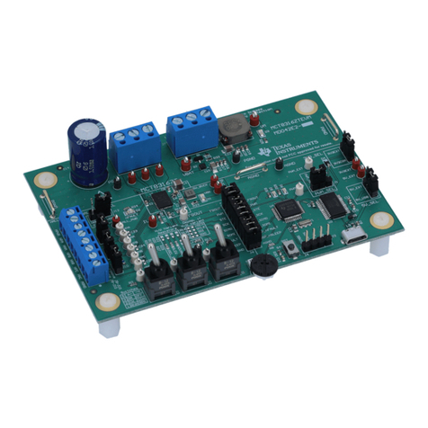
18 TPS546C23EVM2-746 EVM 3D Top View ............................................................................. 22
19 TPS546C23EVM2-746 EVM Top Layer Assembly Drawing (Top View) ........................................... 23
20 TPS546C23EVM2-746 EVM Bottom Assembly Drawing (Bottom View) ........................................... 24
21 TPS546C23EVM2-746 EVM Top Copper (Top View)................................................................. 25
22 TPS546C23EVM2-746 EVM Internal Layer 1 (Top View)............................................................ 26
23 TPS546C23EVM2-746 EVM Internal Layer 2 (Top View)............................................................ 27
24 TPS546C23EVM2-746 EVM Internal Layer 3 (Top View)............................................................ 28
25 TPS546C23EVM2-746 EVM Internal Layer 4 (Top View)............................................................ 29
26 TPS546C23EVM2-746 EVM Bottom Copper (Top View)............................................................. 30
27 Select Device Scanning Mode............................................................................................ 33
28 Configure- Limits and On/Off ............................................................................................ 35
29 ON/OFF Control Pop-up................................................................................................... 36
30 Configure - Advanced ..................................................................................................... 37
31 Configure - SMBALERT # Mask ......................................................................................... 38
32 Configure - Device Info.................................................................................................... 39
33 Configure - All Config...................................................................................................... 40
34 Monitor Screen with 10A total load ...................................................................................... 42
35 Status Screen............................................................................................................... 43
List of Tables
1 TPS546C23EVM2-746 Electrical Performance Specifications ........................................................ 5
2 Test Point Functions ........................................................................................................ 9
3 Jumpers ..................................................................................................................... 10
4 Connector Functions....................................................................................................... 10
5 Key Factory Configuration Parameters.................................................................................. 11
6 List of Test Points for Loop Response Measurements................................................................ 12
7 Test Points for Better Efficiency Measurements ....................................................................... 13
8 TPS546C23EVM2-746 Components List .............................................................................. 31
