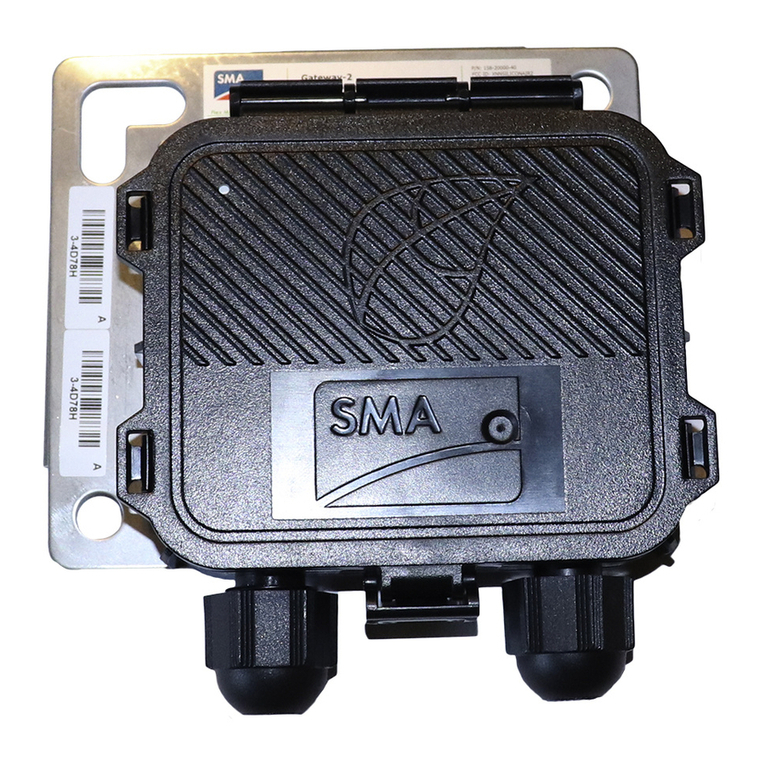
SMA ROOFTOP COMMUNICATION KIT Guide

RoofCommKit-P2-US-IA-xx-11 | 112604-00.01 | Version 1.1
SMA ROOFTOP COMMUNICATION KIT
(RoofCommKit-P2-US)
ENGLISH Installation manual ESPAÑOL Instrucciones de instalación
FRANÇAIS Instructions d’installation

Legal Provisions SMA Solar Technology America LLC
Installation manualRoofCommKit-P2-US-IA-xx-112
Legal Provisions
No part of this document may be reproduced, stored in a retrieval system, or transmitted, in any
form or by any means, be it electronic, mechanical, photographic, magnetic or otherwise, without
the prior written permission of SMA Solar Technology America LLC.
Neither SMA Solar Technology AmericaLLC nor SMA Solar Technology Canada Inc. makes
representations, express or implied, with respect to this documentation or any of the equipment
and/or software it may describe, including (with no limitation) any implied warranties of utility,
merchantability, or fitness for any particular purpose. All such representations or warranties are
expressly disclaimed. Neither SMA Solar Technology AmericaLLC nor its distributors or dealers nor
SMA Solar Technology Canada Inc. nor its distributors or dealers shall be liable for any indirect,
incidental, or consequential damages under any circumstances.
The exclusion of implied warranties may not apply in all cases under some statutes, and thus the
above exclusion may not apply.
Specifications are subject to change without notice. Every attempt has been made to make this
document complete, accurate and up-to-date. Readers are cautioned, however, that product
improvements and field usage experience may cause SMA Solar Technology America LLC and/or
SMA Solar Technology Canada Inc. to make changes to these specifications without advance
notice, or per contract provisions in those cases where a supply agreement requires advance
notice. SMA shall not be responsible for any damages, including indirect, incidental or
consequential damages, caused by reliance on the material presented, including, but not limited to,
omissions, typographical errors, arithmetical errors or listing errors in the content material.
Trademarks
All trademarks are recognized, even if not explicitly identified as such. Missing designations do not
mean that a product or brand is not a registered trademark.
SMA Solar Technology America LLC
6020 West Oaks Blvd.
Suite 300 Rocklin, CA 95765 U.S.A.
SMA Solar Technology Canada Inc.
2425 Matheson Blvd. E
7th Floor
Mississauga, ON L4W 5K4
Canada
Status: 6/7/2018
Copyright © 2018 SMA Solar Technology America LLC. All rights reserved.
ENGLISH

General Warnings
SMA Solar Technology America LLC
Installation manual RoofCommKit-P2-US-IA-xx-11 3
General Warnings
WARNING
All electrical installations must be carried out in accordance with the local electrical standards
and the National Electrical Code® ANSI/NFPA70 or the Canadian Electrical Code®
CSAC22.1. This document does not replace and is not intended to replace any local, state,
provincial, federal or national laws, regulations or codes applicable to the installation and use of
the product, including without limitation applicable electrical safety codes. All installations must
conform with the laws, regulations, codes and standards applicable in the jurisdiction of
installation. SMA assumes no responsibility for the compliance or non-compliance with such laws
or codes in connection with the installation of the product.
The product contains no user-serviceable parts.
For all repair and maintenance, always return the unit to an authorized SMA Service Center.
Before installing or using the product, read all of the instructions, cautions, and warnings in this
manual.
Wiring of the product must be made by qualified personnel only.
ENGLISH

Table of Contents SMA Solar Technology America LLC
Installation manualRoofCommKit-P2-US-IA-xx-114
Table of Contents
1 Information on this Document................................................. 5
1.1 Validity........................................................................................................................ 5
1.2 Target Group.............................................................................................................. 5
1.3 Content and Structure of this Document ................................................................... 5
1.4 Symbols in the Document .......................................................................................... 5
1.5 Typographies in the document.................................................................................. 6
2 Safety ........................................................................................ 7
2.1 Intended Use .............................................................................................................. 7
2.2 IMPORTANT SAFETY INSTRUCTIONS.................................................................... 8
3 Scope of Delivery..................................................................... 11
4 Mounting................................................................................... 12
4.1 Mounting position ...................................................................................................... 12
4.2 Installing the Module ................................................................................................. 12
5 Connection................................................................................ 14
5.1 Connecting the Gateway .......................................................................................... 14
6 Commissioning the Rooftop Communication Kit ................... 17
7 Disposing of the Product.......................................................... 18
8 Contact ...................................................................................... 19
9 Compliance Information.......................................................... 20
ENGLISH

1 Information on this Document
SMA Solar Technology America LLC
Installation manual RoofCommKit-P2-US-IA-xx-11 5
1 Information on this Document
1.1 Validity
This document is valid for:
• RoofCommKit-P2-US (SMA Rooftop Communication Kit)
1.2 Target Group
The tasks described in this document must only be performed by qualified persons. Qualified
persons must have the following skills:
• Knowledge of how an inverter works and is operated
• Training in how to deal with the dangers and risks associated with installing, repairing and
using electrical devices and installations
• Training in the installation and commissioning of electrical devices and installations
• Knowledge of all applicable laws, standards and directives
• Knowledge of and compliance with this document and all safety information
1.3 Content and Structure of this Document
This document describes the assembly and installation of approved accessories in SMA products.
Illustrations in this document are reduced to the essential information and may deviate from the real
product.
1.4 Symbols in the Document
Symbol Explanation
Information that is important for a specific topic or goal, but is not safety-rele-
vant
Example
☐
Indicates a requirement for meeting a specific goal
☑
Desired result
✖
A problem that might occur
ENGLISH

1 Information on this Document SMA Solar Technology America LLC
Installation manualRoofCommKit-P2-US-IA-xx-116
1.5 Typographies in the document
Typography Use Example
bold • Messages
• Terminals
• Elements on a user interface
• Elements to be selected
• Elements to be entered
• Connect the insulated
conductors to the terminals
X703:1 to X703:6.
• Enter 10 in the field
Minutes.
>• Connects several elements to be
selected
• Select Settings > Date.
[Button]
[Key]
• Button or key to be selected or
pressed
• Select [Enter].
ENGLISH

2 Safety
SMA Solar Technology America LLC
Installation manual RoofCommKit-P2-US-IA-xx-11 7
2 Safety
2.1 Intended Use
The SMARooftopCommunicationKit is a communication set for TS4 module technology
components. The SMARooftopCommunicationKit enables direct connection of the inverter to the
Gateway.
SUNNY PORTAL/
SUNNY PLACES
INTERNET
TS4
GATEWAY
(GTWY)
...
...
...
UTILITY GRID
PV GENERATOR
ROUTER
PV INVERTER
with ROOFTOP
COMMUNICATION KIT
AC
DC Ethernet RS485 Radio
Figure 1 : System overview
The SMARooftopCommunicationKit must only be installed in the following SMAinverters with a
firmware version higher than 2.03.61.R:
• Sunny Boy 3.0-US
• Sunny Boy 3.8-US
• Sunny Boy 5.0-US
• Sunny Boy 6.0-US
• Sunny Boy 7.0-US
• Sunny Boy 7.7-US
ENGLISH

2 Safety SMA Solar Technology America LLC
Installation manualRoofCommKit-P2-US-IA-xx-118
The inverter still complies with the standard after the product has been installed.
The product is approved for the US and Canadian market.
All components must remain within their permitted operating ranges and their installation
requirements at all times.
Use this product only in accordance with the information provided in the enclosed documentation
and with the locally applicable standards and directives. Any other application may cause
personal injury or property damage.
Alterations to the product, e.g. changes or modifications, are only permitted with the express written
permission of SMA. Unauthorized alterations will void guarantee and warranty claims and in most
cases terminate the operating license. SMA shall not be held liable for any damage caused by
such changes.
Any use of the product other than that described in the Intended Use section does not qualify as the
intended use.
The enclosed documentation is an integral part of this product. Keep the documentation in a
convenient place for future reference and observe all instructions contained therein.
2.2 IMPORTANT SAFETY INSTRUCTIONS
SAVE THESE INSTRUCTIONS
This section contains safety information that must be observed at all times when working on or with
the product.
The product has been designed and tested in accordance with international safety requirements. As
with all electrical or electronical devices, there are residual risks despite careful construction. To
prevent personal injury and property damage and to ensure long-term operation of the product,
read this section carefully and observe all safety information at all times.
DANGER
Danger to life due to electric shock when live components or cables of the
inverter are touched
High voltages are present in the conductive components or cables of the inverter. Touching live
parts and cables of the inverter results in death or lethal injuries due to electric shock.
• Disconnect the inverter from voltage sources and make sure it cannot be reconnected
before working on the device.
• Wear suitable personal protective equipment for all work on the product.
• Do not touch non-insulated parts or cables.
CAUTION
Increased electromagnetic radiation through the antenna
During operation, the antenna produces an electromagnetic field and can interfere with other
devices (e.g., pacemakers) due to electromagnetic interference.
• Persons must not remain closer than 20 cm (8 in) to the antenna for long periods of time.
ENGLISH

2 Safety
SMA Solar Technology America LLC
Installation manual RoofCommKit-P2-US-IA-xx-11 9
NOTICE
Damage to the enclosure seal in subfreezing conditions
If you open the inverter when temperatures are below freezing, the enclosure seals can be
damaged. This can lead to moisture entering the inverter.
• Only open the inverter if the ambient temperature is not below 0°C (32°F).
• If a layer of ice has formed on the enclosure seal when temperatures are below freezing,
remove it prior to opening the inverter (e.g. by melting the ice with warm air). Observe the
applicable safety regulations.
NOTICE
Damage to the product due to sand, dust and moisture ingress
Sand, dust and moisture penetration can damage the product and impair its functionality.
• Close tightly all enclosure openings.
• Only use listed rain-tight or liquid-tight conduit fittings to attach the conduits to the product.
NOTICE
Damage to communication assembly in the inverter due to an interruption in
the voltage supply during the firmware update
The firmware update to a version higher than 2.03.61.R may take approx. 30minutes. The
inverter must be continually supplied with voltage for the entire course of the firmware update.
• Ensure that the inverter is supplied with voltage during the firmware update to a version
higher than 2.03.61.R.
NOTICE
Damage to the inverter or product due to electrostatic discharge
Touching electronic components can cause damage to or destroy the inverter or the product
through electrostatic discharge.
• Ground yourself before touching any component.
ENGLISH

2 Safety SMA Solar Technology America LLC
Installation manualRoofCommKit-P2-US-IA-xx-1110
After installation of the Rooftop Communication Kit, the secure power
supply operation is no longer supported.
The Rooftop Communication Kit supports the Rapid Shutdown function. A rapid shutdown is
triggered in the event of a grid failure or an interruption of the AC supply of the inverter. Thus
the supply of the outlet for secure power supply operation is no longer possible.
• If a switch and an outlet for secure power supply operation are connected to the inverter,
the connections for the secure power supply operation have to be removed from the
inverter before installation of the Rooftop Communication Kit:
– Disconnect the inverter from all voltage sources (see inverter manual).
– Remove the conductors of the outlet for secure power supply operation from the
terminal block SPS. To release the conductors from the terminals, open the terminals
with a flat-blade screwdriver (blade width: 3.5°mm (0.14°in)).
– Screw out the screws from the SPS terminal block using a flat-blade screwdriver
(blade width: 3.5mm (0.14in)) and pull the terminal block out of the slot.
– Remove the equipment grounding conductor of the outlet for secure power supply
operation from the equipment grounding terminal. To do this, remove the screw (TX
25) and remove the equipment grounding conductor from the inverter; screw each
screw back in (TX 25).
– For secure power supply operation, remove the plug with the switch conductors from
the SPS slot of the communication assembly.
– Pull all conductors for secure power supply operation out of the inverter and uninstall
the switch and outlet of secure power supply operation.
Electrical installations (only applies to North America)
All electrical installations must be carried out in accordance with the local standards and the
National Electrical Code® ANSI/NFPA 70 or the Canadian Electrical Code® CSA C22.1.
• Before connecting the inverter to the utility grid, contact your local grid operator. The
electrical connection of the inverter must be carried out by qualified persons only.
• Ensure that no cables used for electrical connection are damaged.
ENGLISH

3 Scope of Delivery
SMA Solar Technology America LLC
Installation manual RoofCommKit-P2-US-IA-xx-11 11
3 Scope of Delivery
A
G
B
EF
CD
Figure 2 : Components included in the scope of delivery
Position Quantity Designation
A 1 Gateway
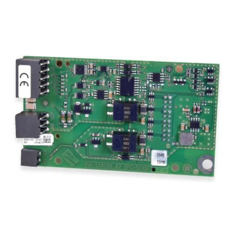
B 1 Module
C 1 20-pole pin strip for mounting the module
D 1 Fastening screw (M5, TX25)
E 1 5-pole terminal block for connecting the Gateway
F 1 4-pole terminal block including 6.8 kOhm resistance in the terminal
points 1 and 2.
G 1 Installation manual
ENGLISH

4 Mounting SMA Solar Technology America LLC
Installation manualRoofCommKit-P2-US-IA-xx-1112
4 Mounting
4.1 Mounting position
DISPLAY
BAT
Max. 30V DC
USB
FCC ID: SVF-KP
IC: 9440A-KP20
MFR
AB
X1 X2
A
B
Figure 3 : Communication assembly in the inverter with mounting position for the module
Position Designation
A Communication assembly
BModule slot M2
4.2 Installing the Module
Procedure:
1. Remove the enclosure lid of the DC Connection Unit. Unscrew all screws (TX25) and remove
the enclosure lid towards the front.
2. Set the screws and the enclosure lid aside and store safely.
3. Plug the 20-pin connector with the long pin side into
the socket terminal strip on the back of the module.
4. Plug the module into the module slot M2. Perform the following steps:
ENGLISH

4 Mounting
SMA Solar Technology America LLC
Installation manual RoofCommKit-P2-US-IA-xx-11 13
• Guide the three guide pins on the
communication assembly through the holes in
the module.
• Carefully push the module down on the upper
edge and on the connection sockets until it
audibly snaps into both side locking tabs of the
communication assembly. The plug on the back
of the module is automatically pushed into the
socket terminal strip of the communication
assembly.
CLICKCLICK
5. Tighten the fastening screw (TX25, torque: 1.5Nm
(13 in-lb)). This additionally fixes the module in
place and grounds it in the inverter enclosure.
ENGLISH

5 Connection SMA Solar Technology America LLC
Installation manualRoofCommKit-P2-US-IA-xx-1114
5 Connection
5.1 Connecting the Gateway
Requirements:
☐ If several Gateways are present in the system, these have to be connected to each other prior
connection to the module in the inverter.
☐ A maximum of threeGateways can be connected to one module in the inverter.
☐ A terminator must be plugged into the last gateway in the row.
Cabling plan of the Gateways:
B A
_+B A
_+ B A
_+ B A
_+B A
_+ B A
_+
B A
_+B A
_+
+− B A S
Figure 4 : Cabling plan of the Gateways with module in the inverter
Cable requirements for the communication cable between Gateway and inverter:
☐ Number of conductors: 4
☐ Conductor cross-section: at least 0.22mm² (24AWG)
☐ Maximum external diameter: 8mm (0.31in)
☐ Maximum cable length: 305m (1000ft)
☐ The conductors should be twisted pairs if the total length of the communication cable exceeds
61m (200ft).
☐ The conductors should be shielded if the cable is laid in a nonmetallic cable raceway.
☐ UV-resistant for outdoor use
☐ The conductors lengths in the inverter must be as short as possible. This prevents contact with
live conductors.
☐ If the conductor is to be installed without conduit, the conductor has to be suited for outdoor
use.
☐ If the conductor is to be installed in a conduit together with live conductors, the conductor has
to be insulated for 600V.
ENGLISH

5 Connection
SMA Solar Technology America LLC
Installation manual RoofCommKit-P2-US-IA-xx-11 15
Assignment of the terminal block:
Terminal block Clamping position Assignment
A B CD E
A -
B +
C B
D A
E S (Shield)
Procedure:
1. If the conductor is installed in a separate conduit, mount the conduit to the enclosure opening:
• Remove the sealing plugs from the network connection opening on the inverter.
• Insert the conduit fitting into the opening and tighten from the inside using the counter nut.
• Attach the conduit to the conduit fitting.
2. Guide the conductors from the conduit into the inverter. In the process, install the conductors in
the inverter such that they do not come into contact with AC conductor.
3. Strip off the conductor insulation by 7mm (0.28in).
4. In the case of fine stranded wire, provide the conductors with a bootlace ferrule.
5. The terminal block with resistor must be inserted for proper operation.
If the terminal block with resistor is not inserted, the system will not function properly.
• Plug the 4-pole terminal block with
inserted resistor into the jack RSI/SPS on
the module.
--RSI-- --SPS--
6. Connect the conductors to the terminal points of the
terminal block in accordance with the labeling and
tighten the screw terminals with the screwdriver.
− + B A S
2
1
7. Ensure that the conductors sit securely in the terminal point of the terminal block.
ENGLISH

5 Connection SMA Solar Technology America LLC
Installation manualRoofCommKit-P2-US-IA-xx-1116
8. Plug the terminal block into the jack RS485 on the
module.
RS485 PORT
--RSI-- --SPS--
ENGLISH

6 Commissioning the Rooftop Communication Kit
SMA Solar Technology America LLC
Installation manual RoofCommKit-P2-US-IA-xx-11 17
6 Commissioning the Rooftop Communication Kit
Limited view of the data in SunnyPortal due to incorrect router
configuration
Due to an incorrect router configuration, the view of system data in SunnyPortal or in
SunnyPlaces is only possible to a limited extent. For unlimited access to system data in
SunnyPortal or in SunnyPlaces, the router must be configured as described in the following.
• Carrying out router configuration for outgoing connections: Permit access to UDP port
1024-65000 and TCP port 443.
Procedure:
1. Commission the inverter (see inverter manual).
2. Activate the user interface of the inverter (see the inverter manual).
3. Start the installation assistant (see the inverter manual).
4. Select the step Configuration of module technology and fill out the individual tabs. In the
last step Status, check the correct configuration.
5. Checking the Rapid Shutdown function of the TS4-R components:
• Ensure that the inverter feeds into the utility grid.
• Turn off the AC circuit breaker. As a result, the Rapid Shutdown function is tripped.
• Measure voltage on the DC inputs of the inverter or watch the display or the LEDs. The
Rapid Shutdown function works properly when the voltage drops to < 30V within 30
seconds and the display and LEDs have gone out after 90 seconds. If the voltage is >
30V and the display and LEDs have not gone out after 90 seconds, the Rapid Shutdown
function is not working properly and the system should not be put into operation. In this
case, check the installation.
6. Register the system in SunnyPortal and detect the TS4-R components in SunnyPortal
(www.SunnyPortal.com).
ENGLISH

7 Disposing of the Product SMA Solar Technology America LLC
Installation manualRoofCommKit-P2-US-IA-xx-1118
7 Disposing of the Product
• Dispose of the product in accordance with the locally applicable disposal regulations for
electronic waste.
ENGLISH

8 Contact
SMA Solar Technology America LLC
Installation manual RoofCommKit-P2-US-IA-xx-11 19
8 Contact
If you have technical problems with our products, please contact the SMAServiceLine. The
following data is required in order to provide you with the necessary assistance:
• Inverters:
– Serial number
– Firmware version
– Special country-specific settings (if available)
• Detailed description of the problem
United States SMA Solar Technology
America LLC
Rocklin, CA
Toll free for USA and US Territories
+1877-MY-SMATech (+1877-697-6283)
International: +1916625-0870
Canada SMA Solar Technology
Canada Inc.
Mississauga
Toll free for Canada / Sans frais pour le Canada :
+1877-MY-SMATech (+1877-697-6283)
México SMA Solar Technology
de México
Mexico City
Internacional: +1 916 625-0870
ENGLISH

9 Compliance Information SMA Solar Technology America LLC
Installation manualRoofCommKit-P2-US-IA-xx-1120
9 Compliance Information
FCC Compliance
This device complies with Part 15 of the FCC Rules and with Industry Canada licence-exempt RSS
standard(s).
Operation is subject to the following two conditions:
1. this device may not cause harmful interference, and
2. this device must accept any interference received, including interference that may cause
undesired operation.
Le présent appareil est conforme aux CNR d'Industrie Canada applicables aux appareils radio
exempts de licence.
L'exploitation est autorisée aux deux conditions suivantes :
1. l'appareil ne doit pas produire de brouillage, et
2. l'utilisateur de l'appareil doit accepter tout brouillage radioélectrique subi, même si le
brouillage est susceptible d'en compromettre le fonctionnement.
NOTE: This equipment has been tested and found to comply with the limits for a Class B digital
device, pursuant to Part 15 of the FCC Rules. These limits are designed to provide reasonable
protection against harmful interference in a residential installation. This equipment generates, uses
and can radiate radio frequency energy and, if not installed and used in accordance with the
instructions, may cause harmful interference to radio communications. However, there is no
guarantee that interference will not occur in a particular installation. If this equipment does cause
harmful interference to radio or television reception, which can be determined by turning the
equipment off and on, the user is encouraged to try to correct the interference by one or more of
the following measures:
• Reorient or relocate the receiving antenna.
• Increase the separation between the equipment and receiver.
• Connect the equipment into an outlet on a circuit different from that to which the receiver is
connected.
• Consult the dealer or an experienced radio/TV technician for help.
Changes or modifications made to this equipment not expressly approved by SMA Solar
Technology America LLC may void the FCC authorization to operate this equipment.
ENGLISH
Table of contents
Languages:
Other SMA Control Unit manuals

SMA
SMA MD.SEN-40 User manual
SMA
SMA NET Piggy-Back Parts list manual

SMA
SMA 485 Data Module User manual

SMA
SMA MD.SEN-US-40 User manual

SMA
SMA MD.485-40 User manual

SMA
SMA MD.485-US-40 User manual
SMA
SMA MD.SEN-40 User manual

SMA
SMA 485 User manual

SMA
SMA JBOX TS4-R-O 600VUL User manual

SMA
SMA Sunny Home Manage User manual