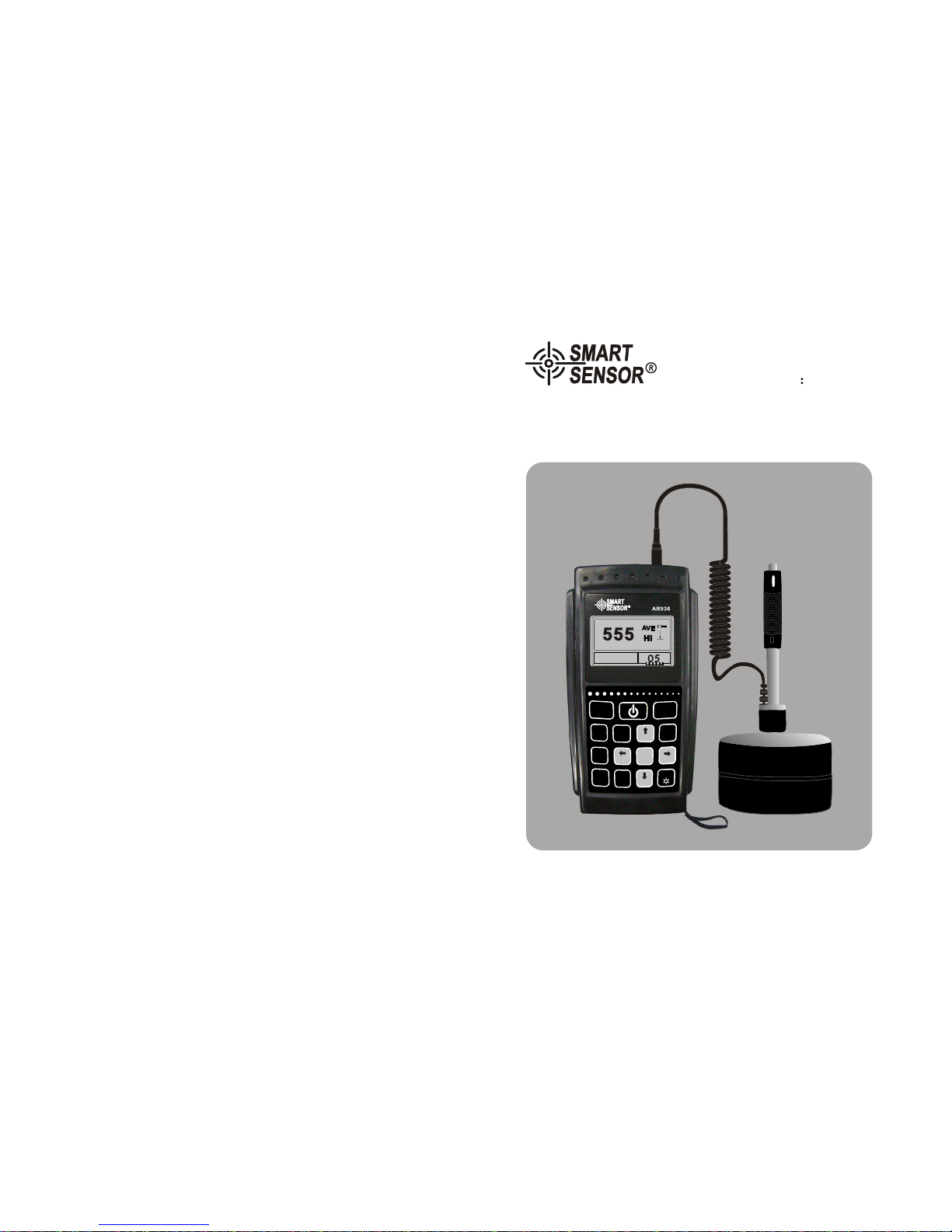
Smart Sensor AR936 User manual
SZ936-2009.10.16
Operation Manual of
Leeb Hardness Tester
Model AR936
555555 VV
AAEE
HlHl
Portable Hardness Tester
Steel and cast steelSteel and cast steel
9
3
0
7
8
2
1
4
6
5
STORE
ENTER
9
3
DEL
0
DIR
7
AVE
8
HARD-
NESS
2
ESC
MAT’L
1
TIMES
4
MENU
6
5

special notice
Turn off the unit before replacement
of battery impact device!

Content
rief
-----------------------------------------------( 9)before operation
requirements on the measured-------------------------------( 9 )
system setting ------------------------------------------------(10)
measuring condition setting ------ ---------------------------(10)
measuring method --------------------------------------------(10)
Working principle and Diagramof the instrument
4.O
peration
Working principle --------------------------------------------(05)
Diagram of the instrument------------------------------------(06)
hardness tester -----------------------------------------------(06)
Main unit------------------------------------------------------(07)
d type impact device---------------------------------------- (07)
irregular type impact device-------------------------------- (08)
3.Technical features
--------------------------------------------------------(04)features
application and its range -------------------------------------(04)
application----------------------------------------------------(04)
application range -------------------------------------------- (04)
model specifications -----------------------------------------(05)
operation condition------------------------------------------(05)
Starting ------------------------------------------- ------ -(10)-----
Load ---------------- ------ ------------------------------ -------(10)
Placement------------------------------ ------------ (10)---------- -
Measuring - ------------ ----------------------------------------(10)
-01-
Maintenance and warranty
1D
Maintenance
put
Warranty warranty
. o not the instrument under the following environment:
a. In risk of splash by water or highly intense dusy environment
b. Air of high content of salt or sulfurate
c. Air of othere chemical substance
d. High humidity and temperature(above 60 90%RH) or in sunlight
2. Don't disassemble the instrument or change the inner struction
3. Alcohol and diluent is erosive to the LCD, clean the housing with cloth
of slight water.
1. Refer to the terms in the card
2. Any damage resulting from unauthorized dismantle of the unit,
improper transport or storage in breach of the manual instruction
as well as unauthorized amendment of guarantee card or lack of
proof will lead to refusal of guarantee service.
D
a.
eclaration:
The battery used must be dealt with according to the local laws,
rules and regulatoins.
b. Our company reserve the right to upgrade and amend the
specifications and design of the instrument and instructions,
they are subject to change without further notification if any.
-28-
Other Items

-02-
-------------------------------------------(15)impact direction setting
average times setting-----------------------------------------------(15)
----------------------------------------- -- (15)material setting ---------
hardness setting ---------------------------------------------------- -(16)
tolorence setting ------------------------------------------------ --- (16)
hardness/intensity setting- ----------------------------------------- (16)
storage management --------------------------------------------- --(16)
review from first group to the last ------------- (17)-------------- ------
reviewing the selected ------- (17)-------------------------------- -------
data transmission ---------------------------------------------- -----(17)
deleting the selected ----------------------------------------- -------(17)
delete all --------------------------------------------------------- ----(17)
confirm of deletion -------------------------------------- ----------- (18)
data review ------------- ------------------------------------------ -- -(18)
system review ---------- ------------------------------------------- -- (19)
LCD brightness setting --------------------------------------- ------(19)
6.D
etails on operation
-------------------------------------------------------------- (12)turn on
turn off --------------------------------------------------------------(12)
measurement -------------------------------------------------------(12)
main menu-----------------------------------------------------------(13)
measuring operation------------------------------------------------(13)
buttons --------------------------------------------------------------(13)
menu tree------------------------------------------------------------(14)
measuring condition setting ---------------------------------------(14)
pick up value --------------------------------------------------------(11)
turn off ----------- -------------------------------------------------- -- (11)
5.Special instruction
User notice
1 After purchase ofthis unit, theuser is expectedto fill inthe guarantee
card withunit stamp,then deliverits copyalong withthe invoicecopy
to ourcustomer servicecenter, orask thedistributor todo so.
Incomplete proof willlead to maintenancewithout guarantee.
2 The instrument enjoysone year guaranteeservice since thepurchase
of theunit, inthis periodif thereis anymalfunction, againstthe
guarantee cardor invoice,contact ourservice centerfor freecharge
service. Incase noguarantee cardor invoicebe presentedour
company willcalculate theguarantee periodsince thedate offfactory.
3 Beyond theguarantee period,the maintenancewill becharged byour
service department.
4 The components like(irregular type , enlonged
cable, specialized softwareetc.) will becharged accordingly.
optional impact device
5 Any damage resultingfrom unauthorized dismantleof the unit,
improper transport orstorage in breachof the manualinstruction as
well asunauthorized amendmentof guaranteecard orlack ofproof
will lead torefusal of guaranteeservice.
6 Please followthe manualinstruction tooperate, ifthere isany
malfunction, contact ourcompany immediately.
-27-

----------------------------------- (22)maintenance impact device -
instrument maitenance -- (22)--------------------------------------- -
instrument check-------------------------------------------------(22)
notice of storage and transport--------- ------------------- ----- (22)
system calibration -- (20)-------------------------------------------- -
program infomation - (20)----------------------------------- ---------
Backlight ----- (21)--------------------------------------------------- -
automatical turn off (21)---------------------------------------------
battery replacement (21)---------------------------------------------
connection of data cable (21)----------------------------------------
7.Trouble shooting
8.U
pkeep and maintenance
A
ppendix
apeendixtwo - ---(24)-------------------------------------- ----------
appendixone -- - - (23)----------------------------------------- --- -- --
apeendix three - -- (25)---------------------------------------------- - -
apeendix four- - - -- (26)----------------------------------------- - -- ---
notice for user - ------------- --------------------------------- ---(27)
-03-
maintenance andwarranty-- --------------------------------- ---(28)
Appendix 4
-26-
time/date setting---------------------------------------------------(20)
No Model Sketch of supportring Remarks
for testing cylindricaloutside
surface
inner cylindrical surface
for testing cylindricaloutside
surface, radius adjustableR10-8
out cylindrical surface
out cylindrical surface
inner cylindrical surface
inner cylindrical surface
out cylindrical surface
or testing sphericaloutside
surface
for testing sphericalinside
surface
inner cylindrical surface
inner cylindrical surface

-04-
1Brief
1.1Features
l Adopting Leeb hardnessmeasuring principle, thisunit can testthe hardness of
most metals.
l 160*80 lattice LCDdisplay allows completeinformation and clearreading.Large
l All display with menuindication makes theoperation easy andconvenient.English
l Alternative white backlightdisplay and USBplug facilitate theopeation in darkness
and communication withPC for dataexchange and configuration.
l The is matchable with7 striking fittings,capable of identifyingthe striking
type automatically,and requires nofurther calibration afterreplacement.
main unit
l The unit canstore up to500 groups ofdate( times 32~1), inwhich each group
contains information ofsingle value, averagevalue, measuring date,
direction, times, material andhardness unit.
impact impact
impact
l With presettingof up andlow limits, theunit alarm automaticallyif reading is
beyond the limits,which facilitates massivemeasurement.
l Battery volume iconon LCD indicatesthe and calibratable with
software. battery power
l When using D/DCtype for steel materialhardness testing,
the reading canbe displayed directlywithout consultation ofthe table.
impact device
l Equipped with PCprogram, this softwaresupports transmission ofthe measuring
results, storage management,statistical analyzing, print and massive parameters
setting to ensurehigher quality andmanagement.
l Professional and niceoutline, smart, portableand reliable performacemakes the unit
operatable in roughenvironment, and immunefrom vibration, strikingand
elecmagnetic interference.
l 4 AAalkaline batteries supportcontinuous operation formore than 50hrs.
and automatical turnoff function.
l 150*80*38mmProduct Dimension
1.2 Application andrange
1.2.1 Application
l Toolingcavity
l Bearing and otherworkpiece.
l Pressure vessel, steamgenerator and itsfailure analysis.
l Heavy workpiece.
l Amounted machanism andpermanent assembly.
l Workpiecewith small testingspace.
l Original record oftesting results required.
l Division of metalmaterial warehouse.
l Quick test formany locations onlarge workpiece.
1.2.2 Measuring range
see appendix oneand two.
Appendix 3
impact device DC(D)/DL D+15 CGE
impacting energy
and mass of
impact body
11mJ
5.5g/7.2g 11mJ
7.8g 2.7mJ
3.0g 90mJ
20.0g 11MJ
5.5g
ball hardness
ball diameter
ball material
1600HV
3mm
carbonized
tungsten
1600HV
3mm 1600HV
3mm 1600HV
5mm
5000HV
3mm
Diameter of
length of
weitht
of
impact
device
impact device
impact device
20mm
86(147)/
75mm
50g
20mm
162mm
80g
20mm
141mm
75g
30mm
254mm
250g
20mm
155mm
80g
max hardness
of workpiece 940HV 940HV 1000HV 650HB 1200HV
Ra average
roughness of
workpiece 1.6 m 1.6 m 0.4 m 6.3 m 1.6 m
min weight of workpiec
direct measure requires
solid support
and intense coupling
>5kg
2~5kg
0.05
2kg
>5kg
2~5kg
0.05~2kg
>1.5kg
0.5~1.5kg
0.02~0.5kg
>15kg
5~15kg
0.5~5kg
>5kg
2~5kg
0.05~2kg
min thickness of
workpiece
intense coupling
min depth of
rigidified layer
5mm
0.8mm 5mm
0.8mm 1mm
0.2mm 10mm
1.2mm 5mm
0.8mm
hardness
300
hv hour
indentation
diameter
indentation
depth
0.54mm
24 m 0.54mm
24 m 0.38mm
12 m 1.03mm
53 m 0.54mm
24 m
hardness
600
hv hour
0.54mm
17 m 0.54mm
17 m 0.32mm
8m 0.90mm
41 m 0.54mm
17 m
hardness
800
hv hour
0.35mm
10 m 0.35mm
10 m 0.35mm
7m --
-- 0.35mm
10 m
application range
of impact device
DC type for
hole or cylinder.
DL type for long
and narrow
channel or hole
D type for
general peices
test
D+15 type for
measuring in
grooves or
recessed
surfaces
C type for
measuring
light and small
piece and
surface
hardened layer
G type forfor
measuring he
avy and rough
cast and forged
pieces
E type for
high
hardness
material
size of ballimpress
-25-
impress
diameter
impress
depth
impress
diameter
impress
depth
Operation
Explanations

-05-
1.4 Operating condition
environment temp operating temp-20~+60 storage temp -30 ~+60
relative humidity 90%
Do not usethe instrument instrong vibration, magneticfield, erosive substanceand
high density powderand dust codictions.
2Workingprinciple andDiagram ofthe instrument
2.1 Workingprinciple
An impact bodywith a sphericaltest tip madeof
tungsten carbide ispropelled against thesample
surface by aspring force andthen rebounds back.
At adistance of 1mmfrom the samplesurface, the
impact and rebound velocity ofthe impact body,
when passing through the coilin its coilerholder,
induces in thecoil and electricvoltage proportional
to the velocities fo themagnet. Leeb hardness as the
follo wing formula:
1.3 Specifications:
appendix two
No Material Leeb hardness
HLD Intension 0b (MPa)
1C350~522 374~780
2
C500~710 737~1670
3Cr 500~730 707~1829
4CrV 500~750 704~1980
5CrNi 500~750 763~2007
6CrMo 500~738 721~1875
7CrNiMo 540~738 844~1933
8CrMnSi 500~750 755~1993
9SSST 630~800 1180~2652
10 SST 500~710 703~1676
-24-
Name Number Remark
1main unit PCS
2D typeimpact device
3Standard leeb hardness block PCS
4A Nylonbrush A PCS
5Support ring PCS
6AA alkalinebattery PCS
7Manual PCS
8Alluminum box PCS
9software CD PCS
10 USB cable PCS
11 B Nylon brushB For G typeimpact
device
12 Irregular type
and support ring
impact device See appendix 3and 4
Standard
packing
No
13 Leeb hardness testing
method for metals. GB/717394-1998
PCS
PCS
Operation
Explanations
optional
accessory
HL=1000×VB/VA
Hl leed hardness
Vb rebound velocity
ofthe impact body
VA impact velocity
ofthe impact body
Table1

-06-
Voltage characteristic ofoutput signal:
2.2
2.2.1 Hardness tester
Diagram ofthe instrument
HV
HRC 127~
364
HV 32~168
23.8~
85.5
40~173
13.5~
95.3
60~290
45~315
material hardness
unit impact device
D/DC D+15 CGEDL
steel and
cast steel
HRC 17.9~
68.5 19.3~
67.9 20.0~
69.5 22.4~
70.7 20.6~
68.2
HRB 59.6~
99.6 47.7~
99.9 37.0~
99.9
HRA 59.1~
85.8 61.7~
88.0
HB 127~
651 80~638 80~683 90~646 83~663 81~646
HV 83~976 80~937 80~996 84~1042 80~950
HS 32.2~
99.5 33.3~
99.3 31.8~
102.1 35.8~
102.6 30.6~
96.8
steel
HB 143~
650
CWT ST HRC 20.4~
67.1 19.8~
68.2 20.7~
68.2 22.6~
70.2
HV 80~898 80~935 100~941 82~1009
Stainless
steel
HRB 46.5~
101.7
HB 85~655
HV 85~802
GC. IRON
HRC
HB 93~334 92~326
Nc
IRON HB 131~
387
c. alum HB 19~164 23~210
HRB 23.8~
84.6 22.7~
85.0
brass
HB
HRB
bronze HB
copper
HB
Appendix
Appendix one
-23-
Main unit
Impact device
Impact phase
time
Rebound
Phase
Operation
Explanations
555555 VV
AAEE
HlHl
Steel and cast steelSteel and cast steel
9
3
0
7
8
2
1
4
6
5
STORE
ENTER
9
3
DEL
0
DIR
7
AVE
8
HARD-
NESS
2
ESC
MAT’L
1
TIMES
4
MENU
6
5

-07-
2.2.2 Main unit
2.2.3 D typeimpact device
release button load
supporting ring
tube guide tube coil holder
connecting cable impact head
-22-
8.1 Impact device
l After operation for1000~2000 times, clean pipe and
with nylon brush.For cleaning thepipe, take outthe body by
unscrewing the supportring, screw thenylon brush anticlockwiseinto the pipeuntil
the bottom thenpull out, repeatthis five times,then re-install the
and support ring.
impact device impact device tube
impact device tube
impact device tube
l After operation releasethe impact device tube.
l Forbid to useany lubricant for .impact device tube.
8.2 Instrument maintenance
l When checking withRockwell hardness blockand finding theerror over 2HRC,it is
recommendable to replacethe head or resulting from ballwearing.impact device
l In case thatthere is anymalfunction of theinstrument, the usershall not dismantleor
replace any componentof the instrument,please fill inthe guarantee cardand return
the unit toour maitance department.
9. Instrument checkup
The checkupperiod shall notbe more thanone year,the users candecide its regular
checkup period attheir convenience.
10. Storage andtransport
l Keep the unit from the vibration,high magnetic fieldand erosive substance,humid
zone and dustyroom in normaltemperature.
away
l Keep the originalpackage, the instrumentcan be transportedon 3 levelroad.
µç³ØÃÅ
µç³ØÃÅ
LCD display
Keypad
Impact device socket
rear cabinet
battery door
Vibration-proof suit
USB socket
Battery
back sidefront side
µç³ØÃŵç³ØÃÅ
8. Maintenance and warracnty
Operation
Explanations

-08-
2.2.4 Irregular impact device
3.Technicalfeatures
lSee table2 for and reading repeatibilitytolorence
No impact device hardness of theblock tolorence of the
reading reading
repeatibility
1D760 30HLD
530 40HLD 6 HLD
10 HLD
6 HLD
10 HLD
2DC 760 30HLDC
530 40HLDC 6 HLDC
10 HLDC 6 HLD
10 HLD
3DL 878 30HLDL
736 40HLDL 12 HLDL 12 HLDL
4D+15 766 30HLD+15
544 40HLD+15 12 HLD+15 12 HLD+15
5G590 40HLG
500 40HLG 12 HLG 12 HLG
6E725 30HLE
508 40HLE 12 HLE 12 HLE
7C822 30HLC
590 40HLC 12 HLC 12 HLC
l Measuring range HLD 170~960 HLD
l Measuring direction: verticaldown, side down,horizontal, side upand vertical down
-21-
6.11 Backlight
The white backlightfacilitates operation indarkness, pressing buttonto turn on/off
the light inmain menu interface.
6.12 Auto turnoff
lThe function isto save theenergy
lIf no furtheroperation within 5min the instrumentwill turn off automatically
lThe battery iconwill be blankif there islow battery
6.13 Battery replacement
After long timeoperation, the battery icon becomesfaded, the moreblack part the
more battery volume;after exhaustion ofthe battery,the batter iconshows ,this
means to replacethe battery immediately.
Refer the followingfigure to installthe battery:
6.14 Data transmissioncable connection
Plug one endof the cableinto the USBsocket at theleft of thehost while theother
end into PC'sUSB socket.
7. Trouble shooting
Problem Analysis Action
Fail to turnon Exhaustion of battery Replace battery
Wrong polarityconnection Connect the battery
in proper polarity
Blur reading Low battery Replace battery
Replace the batteriesas follow steps:
the unitlturn off
lTakeoff thevibration-proof glove on
the instrument, andopen the battery
door and takeout the oldbatteries.
lInsert the 4fresh batteries with
correct polarity, then closethe battery
door and takeon the glove.
lTurn onthe instrument tocheck if it
works properly.
lPay attention tothe polarity ofthe
batteries, otherwise itmay damage
the instrument.
battery door
Battery µç³ØÃÅ
µç³ØÃÅ
--
++
--
++
--
++
--
++
positivepolarity
negativepolarity
l Material: steel &cast-steel, alloy toolsteel, stainless steel,gray cast iron,nodular cast
iron, cast alluminumalloy, copper-zinc alloy,copper-tin alloy,pure copper,and forged
steel.
Operation
Explanations
Table2

l Hardness unit ( HL) HB HRB HRC HRA
HV HS
l Display 160*80 lattice LCDdisplay
l storage up to 500groups ( times:32~1)Data impact
l Operating voltage 6V
l Continuous operating time 50hrs without backlight.
4Instrument operation:
4.1 Before operation
4.1.1 Requirements ofthe measured.
The surface ofthe measured mustmeet the requirementscontained in table3.
l The surface ofthe measured mustbe no morethan 120 .
l The roughness cannot be toohigh, otherwise errorsmay be occurred.The measured
surface must bepolished and blareas smooth andflat as possiblewithout oil smear.
l Weightof the measured:for the measuredof more than5kg, there isno need to
support; for thatof 2~5kg orof thin wallsconstruction, a supportmust be applied
while operating toavoid distortion, warpageand movement; formiddle scale
workpiece, it mustbe placed inbalance on aflat and concretesurface without any
vibration or moving.
l Curve surface workpiece:the testing surfaceshould be The smallsupporting
ring or irrregulartype supporting ringshall be usedfor testing theworkpiece which
has its curvatureradius less than30mm(forD,DC, D+15, C,E and DLtype
) and biggerthan 50mm(G type ).
as flat.
impact
device impact device
-09-
-20-
6.8.2 Time /date setting
Current time/date displayson the LCDin format of
month/date/year hr/min.
Press number buttonsto input thenumber, thecursor
will move fromleft to rightrepeatedly.
Press ENTER button to completethe setting.
Press ESC button to cancelthe change.
6.9 System calibration
First operation, oruse after along time, theinstrument and the must be
calibrated with theprovided leeb hardnessblock. Whenseveral are
provided with , every only need onecalibration, and noneed
to re-calibrate whenreplacing .
Press menu toenter into systemcalibration submenu.
impact device
impact devices
main unit impact device
impact device
11 0/05/2005 11:02
time / date setting
After testing,averages display.
Press [ ][ ]to inputreal value.
Press ENTER button to completethe calibration.
Press ESC button to exitthe operation.
Calibraton range: 15hl.
system calibration
times
testing 5 times
Software Calibration
Average =780
Real Value=
778800
6.10 software info
press menu toenter into mainmenu
This interface showsthe info aboutthe instrument and
the plug-in software
The software versionno and plug-insoftware indentifier
is subject tochange without furthernotification.
Storage Manager
system calibrationsystem calibration
version No:AR936 B01
indentifierAR963BETA01
SN: 93600000
Setting the direction asimpact
With leebhardness block, test5 locatons indirection
of vertical downward.
System Configuration l The workpiece mustbe of enoughthickness, for the thickness please see
the appendix table3. minimum
l For the workpieceof rigid surface,the surface mustcomply with therequirements
prescribed in theappendix table 3.
l Coupling: for thelight workpiece, itmust be coupledwith the solidsupporting
body,the two couplingsurface must beflat and smoothwithout too muchcoupling
agent applied.The testing directionmust be verticalto the couplingsurface. For
the workpiece oflarge area,long stem shape,or crook shape,even its weightand
thichness are enough,it is stillpossible to findthe distortion andunbalance which
Press [ ][ ] tomove the cursorto software Info.
Press ENTER button to enterinto software info.
Operation
Explanations

-10-
4.1.2 Instrument system setting: see6.8 for details.
4.1.3 Measuring condition setting:see 6.5 fordetails.
4.2 Measuring method:
l Calibrate the unitwith the providedhardness block beforeoperation,and its
and repeatibility shallbe in linewith the table2. tolorance
4.2.1 Starting
l Plug the head in thesocket at themiddle of theunit.impact
l Press [ ]button to turnon the unie.
4.2.2 Loading( figure1)
l Push down theload to lock the body; for DCtype
the load stemon the surfaceof the workpiece;for DC
insert the stemuntil stop forloading process.
tube impact impact device,
adsourb impactdevice,
4.2.3 Placement (figure2)
Clamp the strikingsupport ring againstthe the surfaceof the workpiecein the
selected direction vertically.
-19-
6.8 System configuration
Press menu toenter into mainmenu
Press [ ][ ] topoint the cursorto the System
configuration
Press ENTER button to enterinto the menu.
Auto storage Eliminate the bigerror
Auto data transmission]
[Button sound][Alarming sound]canbe turned
on/off bypressing the confirmbutton
l Auto storage: settingon will autostore the currentgroup data aftergiving average
reading.
l Eliminate the bigerror: setting onwill auto eliminatethe big errorbounding the 3
regulations after theadvance ending ofcomplete measurement bypressing average
button. If adata is eliminated,new data shallbe supplemented toreach the times
preset.
l Auto data transmission:setting on willoutput the currentdata through USB
interface in textformat after averagereading is given.
l Button sound: settingon makes thebuzzer beeps onceat every buttonoperation.
l Alarm sound: settingon makes thebuzzer beeps oncefor a longtime when the
measurement is beyondthe allowance limits.
storage manager
system configurtionsystem configurtion
measuring
condition setting
auto storage off
eliminate the big error off
auto data transmission off
button sound on
alarming sound on
LCD brightness setting
time/date setting
6.8.1 LCD brightnesssetting
LCD brightness setting
press [ ] toincreasethe brightness
press [ ] todecrease the brightness
Press [ ]to increase thebrightness
Press [ ]to decrease thebrightness
Press ENTER button to completethe setting.
Press ESC button to cancelthe change
figure 1 2figure 3figure
4.2.4 Measurement( figure3)
l Press the releasebutton at thetop of the device to measurewhile the
workpiece, device and operatormust stand steadilyand the force
should be inline with theaxis of device.
impact
impact impact
impact
l Normally test 5times for eachlocation of theworkpiece. Themax difference
between these resultsshould not be 15HLwithin
Note:
test the blockin direction ofvertical down for5 times withthe demarcated Leeb
tester, andtake the arithmeticaverage as thehardness value ofthe block. Ifthe
value is beyondthe limit, usesystem calibration functionto calibrate theunit.
lead to incorrectmeasuring, so reinforcingor supporting atthe back ofthe workpiece
is necessary.
Press [ ][ ] tomove the cursorto the desired.
Press ENTER button to changeor enter intothe
change interface.
Press ESC button to exit
Operation
Explanations
-11-
impact device
distance between
center of the 2 impress the distance between the
center and edge of workpiece
DDC 35
DL 35
D+15 35
G48
E35
C24
table 3
4.2.5 Read thevalue
l Takethe average ofreadings from manyvalid testing locationsas a Leebhardness
data.
l Before the Leebhardness signal HLis the hardnessreading. Afterthat is thetype
of striking fittingtype. For example,780HLD means thetested hardness is780 with
type D impactdevice.
l For conversion fromLeeb reading, acorresponding hardness singalshall be
placed after thereading, for example,420HVHLD means theVickerreading is 420
with the typeD impact device.
Note: The differentimpact device wiillhave the different hl valuereading, for
example:
4.2.6Turn off
-18-
are you sure to delelte?
YesYes NoNo
6.6.6 Confirm delete
6.7 Data review
No. 001 12/03 652HL
No. 002 12/03 587HL
No. 003 12/03 820HL
No. 004 12/03 693HL
No. 005 12/03 783HL
No. 006 12/03 782HL
No. 007 12/03 579HL
No. 008 12/03 687HL
No. 001 12/03 514HL
No. 002 12/03 785HL
No. 003 12/03 516HL
No. 004 12/03 789HL
No. 005 12/03 570HL
No. 006 12/03 852HL
No. 007 12/03 523HL
No. 008 12/03 796HL
Every LCD pagedisplays up to8 groups of
numbers, date andaverages
Press [ ][ ] topage up/down
Press ESC button to exitreview
Press ENTER button to callcursor for furtherreview.
A confirminterface appears whendelete the datastored.
Press [ ][ ] tomove the cursorto Yes and press
ENTER button to deletethe data.
Press [ ][ ] movethe cursor toNo and press
ENTER button to cancelthe delete. Regardlessthe
cursor position.
Press ESC button also leadto delete cancellation.
Press [ ][ ] toselect the groupdisplayed.
Press ESC button to exitreview
Press ENTER button to callcursor for furtherreview
511 513 516
514 515
Max: 516 Min: 511
Number 001 12/03/02
average= 514HL
D 05 times
steel and cast steel
press ““ button to turnoff.
5Special instruction:
l Replacement of battery must be performedafter turn off the
unit, otherwise,the can not beidentified and damage the unit.
impact device
impact device might
l Any distance betweenimpresses and thedistance between thecenter and theedge of
the workpiece shallbe in linewith the regulationof table 3.
l For specific material,a comparison testmust be performedto get aconversion map if
you want tochange the Leebreading into otherhardness value.This method isthat
using properly calibratedLeeb tester andthe desired testerto test onthe same
workpiece at 3locations nearby thetarget locationand get 5groups of theLeeb
readings. Thentake the averageof these readingsand these fromanother tester to
make a conversioncurve which atleast must involve3 pairs ofsampling readings.
l The magnetism ofthe workpiece shallnot be morethan 15 gauss.
6.6.5 Delete all
Delete Allwill delete allthe data storedin memory.
Press [ ][ ] topage up/down andreview the
averages, measuring conditionsand single readings.
Operation
Explanations
-12-
Leeb hardnesstester
impact device
DD
The instrumentwill check the and show onthe LCD, checkif the display
is right ornot, then theunit enters intothe main menudisplay.
impact device
6.3 Measurement
After turn on,the unit entersinto the mainmenu as shownbelow:
-17-
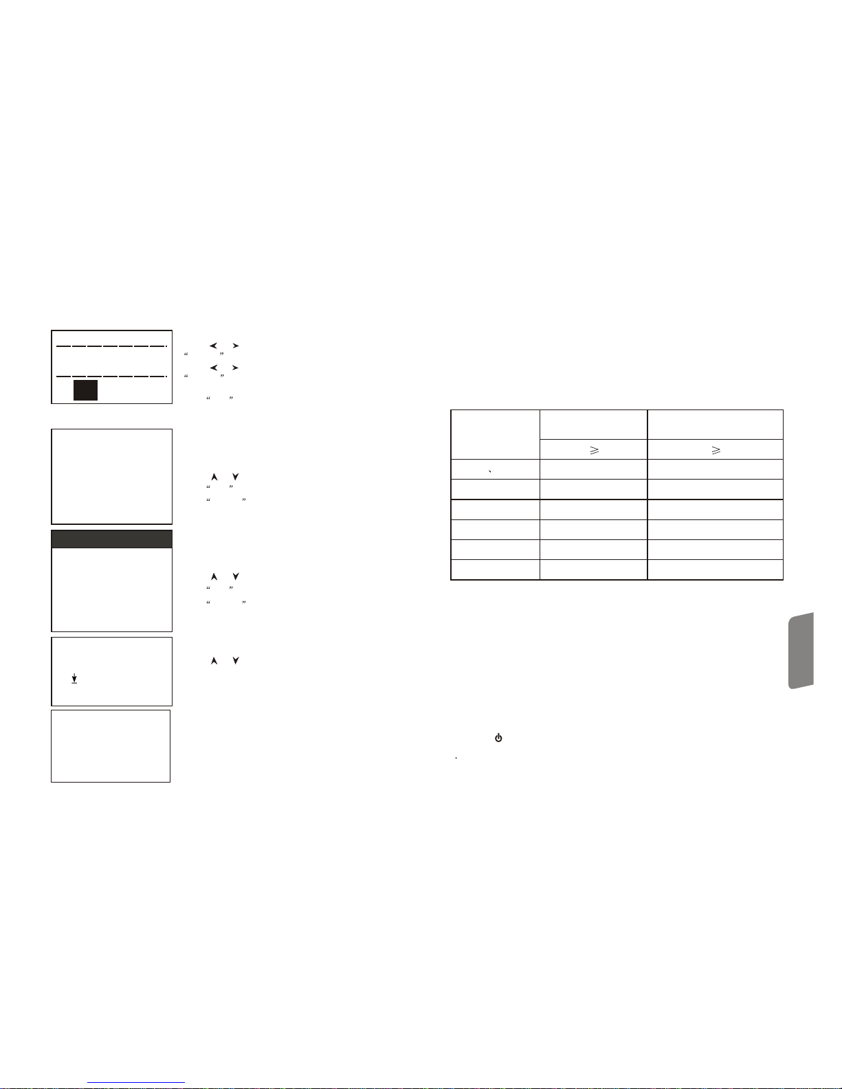
6.6.1 Review fromthe firstgroup/review fromthe lastgroup
The formerdisplays the datastored from thefirst goup
The later displaysthe data storedfromt the lastgroup
6.6.2 Review fromthe selectedgroup
lReview From theSelected Group will
display the startgroup interface
lPress number buttonsto input thenumber
lPress ENTER button to confirm thechoice
lPress ESC button to cancelthe change
6.6.3 Data transmission
Data Transmissionwill transmit thedata in textfrom USB interface.
Select thestart groupfrom
001 to 010
00 01
6.6.4 Delete theselected group
lDelete Selected Groupwill show thethe
interface of theselected group tobe deleted
lPress the numberbutton to inputthe number
lPress ENTER button to confirmthe choice
lPress ESC button to cancelthe change
Note:
1. If thegroup number isbeyond the existed,all the existedgroups will bedeleted
2. There isno differnceto input thefirst group numberor final groupnumber, ex,
delete 1 to5 equals delete5 to 1
3. After deletion, thenumber of thestored group willbe re-numbered
4. In deleting,especially for singlegroup delete, forre-number the existingstored data,
more 30 seconds is required,the instrument shallnot be turnedoff toavoid messing
up the data.
selectable group from
001 to 017
0001
To
001
Press the [ ] [ ] to move thecursor to the
desired function
Press ENTER button to confirmthe choice.
review fromthe firstgroup
review formthe lastgroup
review fromthe selectedgroup
data transmission
delete theselected group
delete all
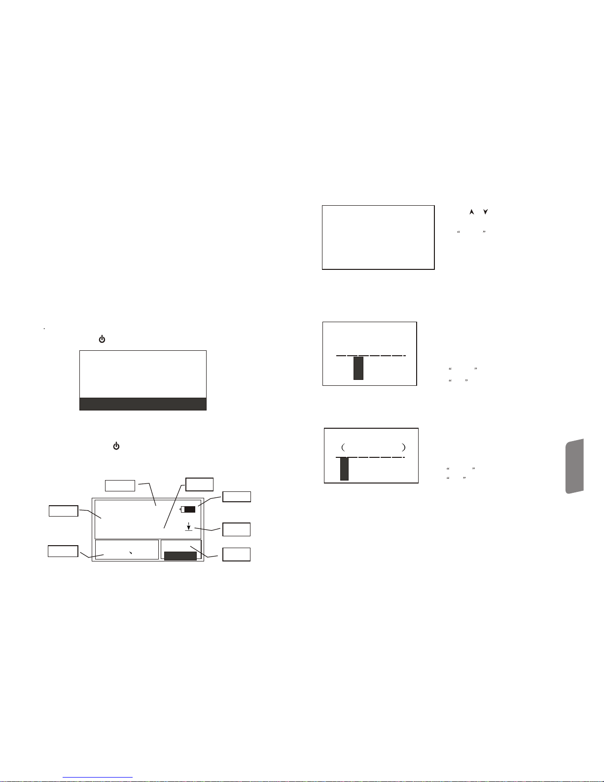
AVE
784
HL
CWT ST 04
COUNTCOUNT
material
reading
average hardness
unit
battery
impact
direction
impact
times
lNormally, thereading cannot bestored if the times is lessthan the presetvalue.
If you wantto store thecurrent reading, pressthe Average button toend the
measurement and storethe value.
impact
lThis performance ofadvance end ofmeasurement by pressingAverage button disable
the functions ofautomatical storage andautomatical transmission inthe system munu.
lOnly D typeand DC type enable the intensiontesting function, ifother
are used thehardness/intension settings cannotbe changed. Incase that
if chage thesetting as Intensionwith D/DC , then changethe
with others, theHardness/Intension setting willbe changed intoHardness
automatically.
impact device
impact devices impact devices impact
devices
lIf the settingis Intension, thehardness unit resetcannot be performed.
lNot all thematerial hardness canbe converted intoothers, if thematerial is changedthe
tester will berestored into Leebhardness unit automatically. So materialsetting msut
be done beforethe hardness unitsetting in processof condition setting.
6Details ofinstrument operation
6.1 turn on:press[ ]to turnon asshown below:
6.2 In any case,press [ ] to turn off the unit.again
Operation
Explanations
-13-
6.3.1 Main menuinstruction
Battery: shows the residualbattery volume.
direction:current direction
Average: when the preset times is reached,the average valueshows.
Hardness unit:current unit
Reading: current single testingreading(without average alert),current average(with
average alert).
denotes value aboveconvertable or measurerange, denotes value belowthe
convertable or measurerange.
Material: current material seting.
times: shows the times done withpreset viaTimes button.
Times givesthe info ofthe times and Singlereview gives thesingle readings
with is timesof a singlereading.
6.3.2 Measuringoperation
At thisinterface, each testingwill be displayed,and the times added with1, if
the reading isbeyond the , the buzzergives a longbeep; when presettimes
is reached thebuzzer 2 shortbeeps, then theaverage shows after2 seconds withthe
buzzer gives ashort beep.
6.3.3 Button operation
l Press STORE button to storethe current groupreading, after theaverage is given.
The datacan only bestore once.
l Press DEL button to deletethe last singlereading, before theconfirmation of the
following dialogue:
Impact impact
Impact impact
impact
impact
tolerance
are you sure to delete?
yesyes nono
l Press AVE button to endthe measurement advancelybefore the preset
times and showsthe average. impact
l Press[ ]to turnon / off the backlight(thisfunctions only inthe main menuinterface)
l Press MENU button to enterinto main menu
l Quick set button
l Press the DIR button to setthe direction.
l Press the TIMES button to changethe times set, firstpress will displaythe
current the timesset, each pressadd 1 until32, then goback to the1.
impact
l Press[ ] [ ] button toreview the singlereadings, and pressthe Esc torestore the
average or lastreading display,press the [ ] or [ ] can reviewthe info inorder.
-16-
6.5.4 Hardness unit setting
mild steel
high carbonsteel
chrome steel
current material
hardness unit
HV HB HRC
HS HRB HRA
HLHL
6.5.5 limit settingTolerance
6.5.6 Hardness/intension setting
Press the [ ] [ ]to move thecursor to thedesired
material
Press ENTER button to confirmthe choice
Press ESC button to cancelthe change
Press [ ][ ] or[ ] [ ] to movethe cursor tothe
desired unit
Press ENTER button to confirmthe choice
Press ESC button to cancelthe change
Note:
1. Only thehardness unit availablefor convert with
suitable and material, forothers this
cannot be displayed.
impact device
2. Select materialbefore hardness unitsetting
3. Aftermaterial setting, thehardness unit will
be restored toHL automatically.
Press the Numberbutton to inputthe number andthe
cursor will moverepeatedly from leftto right.
Press confirm toconfirm the choice
Press Esc tocancel the change
Note:
1. If thesetting is beyondthe range, theinstrument will
alert you toreset.
2. If thelow limit isbigger than thetop limit, the
instrument will reversethe setting.
Press Confirm toselect hardness/intension, the
cursor shifts betweenthe hardness andintension
Note: 1. only D/DC are capable of
intension measurement, forthe others thischocie is
Hardness only.
impact device
tolerance limit
low limit top limit
00 200 0890
material
hardness unit
tolerance limit
hardness/
intension hardnesshardness
Press [ ][ ] to movethe cursor toStorage manage
Press ENTER button to enterinto storage managemenu.
If there isno data stored,“ NO DATA”shows.
measuring
condition setting
storage managestorage manage
By pressing the[ ] [ ] button tomove the
cursor toYesand click theConfirm button to
confirm the deleteof last singlereading.
By pressing the[ ] [ ] button toNo and
click the ENTER button to cancelthe delete.
Regardless the cursorposition, pressing the
ESC button can alsocancel the delete
operation.
6.6 Storage manage
Press the Menuto enter intomain menu
Operation
Explanations

-14-
l Press MAT L button will changethe material seting,each press willcycle the materials
preset in theinstrument, and putthe hardness asLeeb unit. Soit is necessaryto set
material before hardnessset.
Note: The so calledconversion means thatbased on themassive tests forLeeb
hardness and otherhardness, a correspondingmap is setup, and adoptingthis map the
tester calculates andconverts the Leebhardness into otherunits.
6.4 Menu tree
All the instrumentparameters's configuration andadded functions canbe performed
with menu opertion,press the Menubutton to enterinto the mainmenu interface.
main menu interface
measuring condition setting
storage manager
system setting
system calibration
program info
impact
tolerance
direction
average times
material
hardness unit
hardness/intension:hardness
review from firstgroup
review from thelast group
review from theselected group
data transmission(preserved)
delete the selectedgroup
delete all
automatic storage: off
eliminate the maxerror:off
auto data transmission:off
button sound: on
alarm sound: on
LCD brightness setting
time/date setting
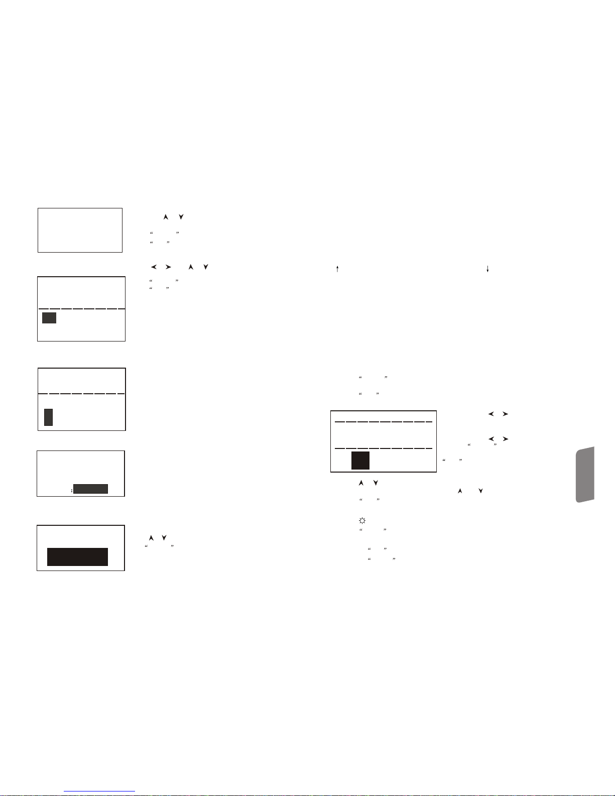
6.5 measuring conditionsetting
Press Menu buttonto enter intomain menu interface.
measuring condition settingmeasuring condition setting
storage manager
system configuration
l Press ENTER button to enterinto
measuring condition settingmenu.
l Press [ ]to review upward.
l Press [ ]to review downward.
Press [ ][ ] buttonto move thecursor to thedesired
condition and press ENTER button to confirmchoice.
Note: 1. Ifthe hardness/intension isset as intension,
hardness cannot beselected, the cursorjump over the
Hardness unit choice.
Only D/DC are available to
intension measuring, whenusing other ,
the cursor isnot able tobe moved tothe Hardness/
Intension choice.
impact device impact device
6.5.1 direction settingimpact
6.5.2 Averagetimes setting Availableto select from1 to 32.
Press the Numberbutton to inputthe number
and the cursorwill move repeatedlyfrom left
to right.
Press ENTER button to completethe change.
Press ESC button to cancel the change.
Impact
tolerance
direction
average times
material
hardness unit
hardness / intension: hardness
impact direction Press [ ][ ] tomove the cursorto the
desired direction setting.impact
Press the ENTER button to confirmthe choice.
Press the ESC button to cancel the change.
average times
00 3
6.5.3 Material setting
If the Hardness/Intensionis set ashardness, the followingmaterials will showon LCD
steel & cast-steel,alloy tool steel,stainless steel, graycast iron, nodularcast iron, cast
aluminium alloy,copper-zinc alloy, copper-tinalloy, purecopper, forgedsteel
Press the ENTER button to confirmthe choice
Press the ESC button to cancelthe change
Note: After materialreset, the hardnessunit will
automatically restore itselfto HL
2. Before selectinghardness unit, setthe material.
copper/zinc alloycopper/zinc alloy
copper-tin alloy
pure copper
forged steel
If the Hardness/Intensionis set asIntension, the followingselectable material shows:
Mild steel, highcarbon steel, chromesteel, chrome/vanadium steel,chrome/nickle steel,
chrome/molybdenum steel, chrome/nickle/molybdenumsteel, chromansil,super high
intension steel andstainless steel.
Press the [ ] [ ]to move thecursor to the
desired material.
-15-
l Press the HARDNESS button to setthe hardness unit,each press changethe unit of
the hardness, ifthe current setis intension itwill go asLeeb hardness.
Operation
Explanations
Table of contents
Other Smart Sensor Test Equipment manuals

Popular Test Equipment manuals by other brands

Agilent Technologies
Agilent Technologies InfiniiVision 5000 Series Service guide

BEVS
BEVS 1605 user manual

Keysight Technologies
Keysight Technologies U3020AD01 User's and service guide

Credence
Credence CTE701A user guide

Reed Instruments
Reed Instruments R7800 instruction manual

Rebel TOOLS
Rebel TOOLS MIE-RB-168 quick start guide


