99-01051-20 A0
UX60-RFK-685
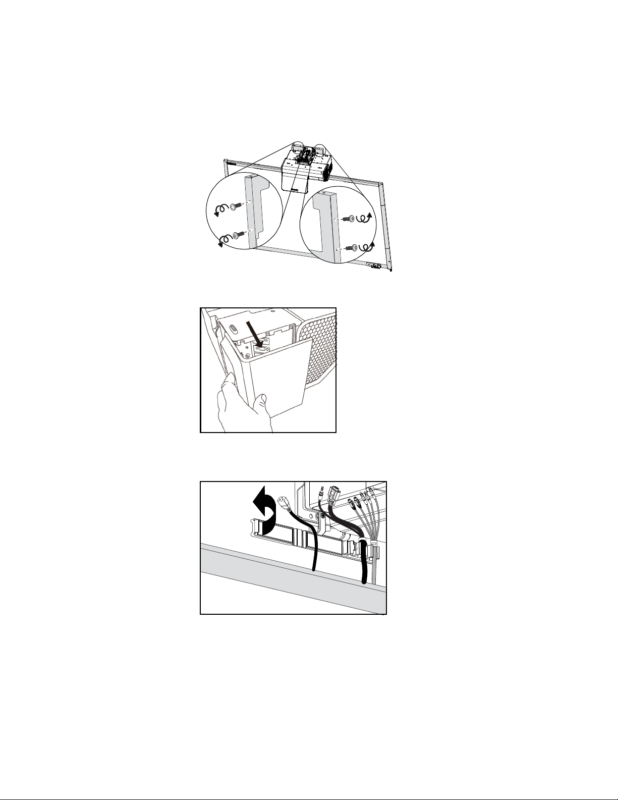
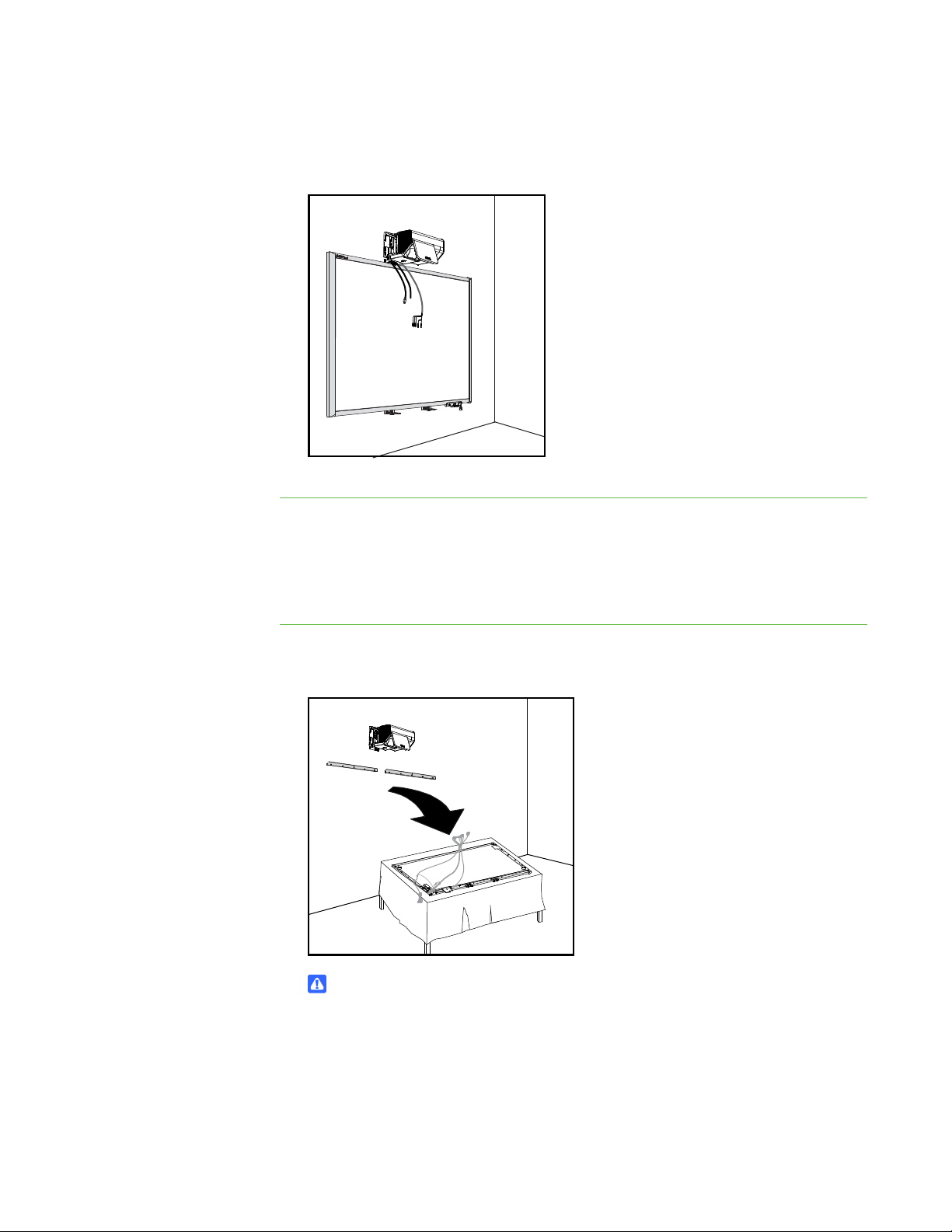
Installing Brackets
to Minimize Distortion in
Your SMART Board™ 685ix
Interactive Whiteboard
System’s Projected Image
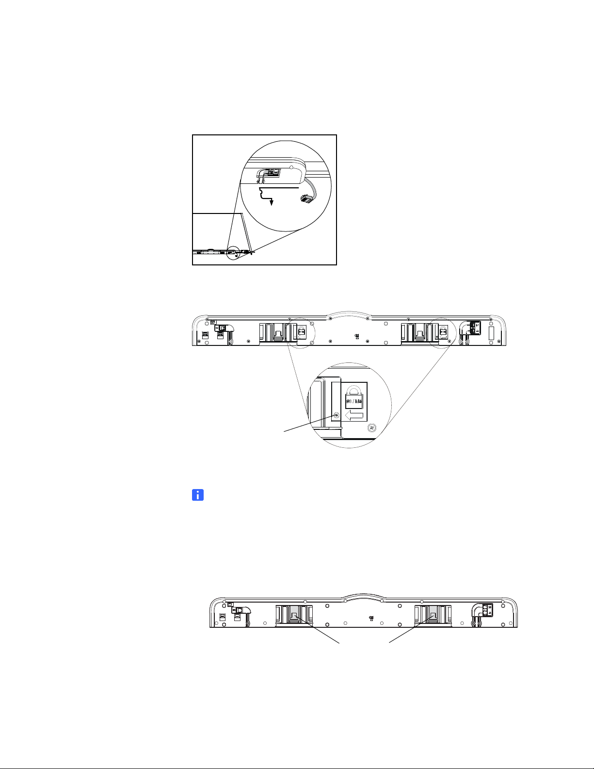
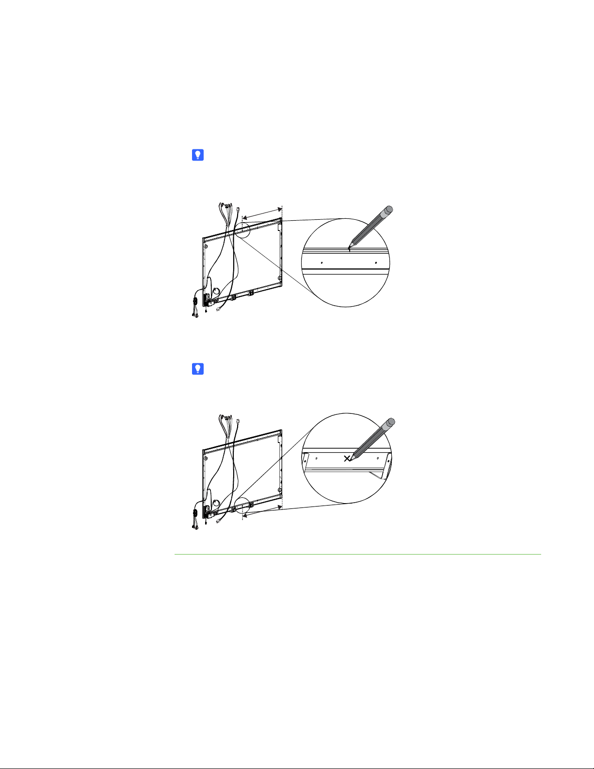
Follow these instructions to install brackets on your SMART Board™ 685ix interactive
whiteboard system to minimize distortion in the projected image. This distortion results
from a slight curve in your interactive whiteboard’s screen.
IMPORTANT
• These instructions apply to SMART Board 685 interactive whiteboards
installed on wall-mount brackets only.
• This kit includes instructions and parts for installation on wood and metal stud
walls and certain masonry wall types only. If you need to install your
interactive whiteboard system on reinforced concrete walls, walls with plaster
lath finishing, walls of unusual construction or other types of walls, refer
to your local building authority for instructions, recommendations and safe
work practices.
This Kit Contains Tools Required (but not included)
• two corner brackets
• one adjustable spacer (two parts)
• two snap toggle anchors
• two masonry anchors
• two 2 1/2" machine screws
• two 1 1/2" masonry screws
• two 5/16" washers
• eight 1/2" screws
• Phillips® No. 2 screwdriver
• tape measure or ruler
• a carpenter’s level
• pencil or other marking device
• power drill with a Phillips No. 2 bit
• 1/2" or 13 mm wrench