SmartEv Scatalo User manual

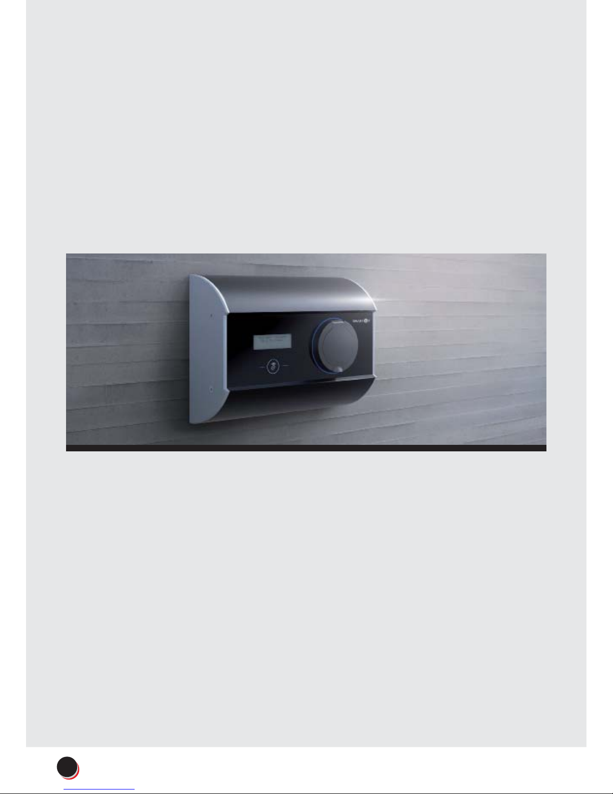
SmartEv Scatalo
INSTALLATION MANUAL
3.7 kW | 7.4 kW | 11kW | 22kW
A unified and consistent use of these guidelines is one of the
key ways by which we will visibly distinguish and strengthen the
equity and hence the value of our brand over the medium and
long-term.
These guidelines are designed to help everybody involved
in the production of our communications and they also play
an important role in building our brand. Please take time to
read and understand them: The design principles have been
carefully considered and developed to ensure that our visual
identity is always consistent. They will continue to evolve as our
requirements grow to become a fully comprehensive guide for
all identity applications.
Thank you for choosing
SmartEv Scatalo charger.
Welcome to the award
winning world of SmartEv.
If you require any further
help and advice when
installing this product,
please call our helpline on
01707 443179.
(Lines are open Monday to
Friday from 7am to 4:30pm).
2www.smartev.co.uk | 01707 443 179
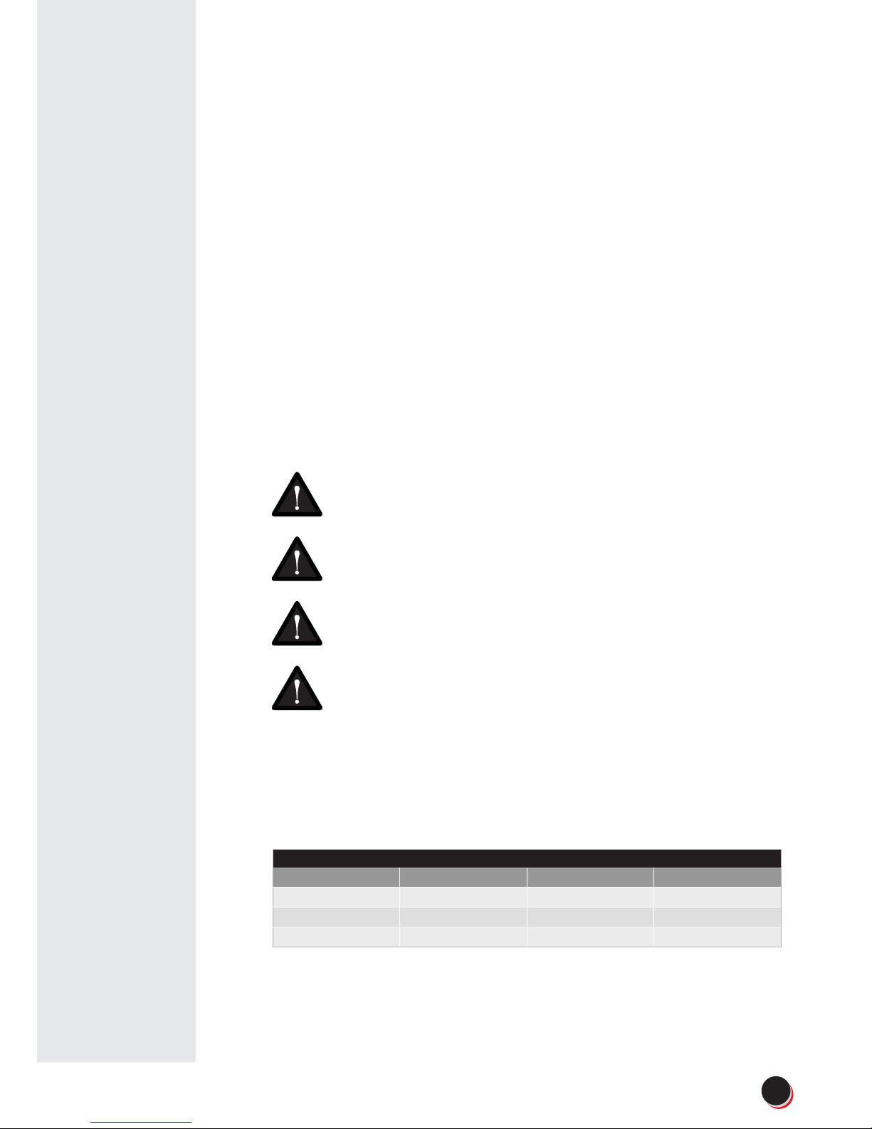
General notes
At various points in this manual you will see notes and precautionary
warnings regarding possible hazards. The symbols used have the following
meanings:
Warning !
Indicates a potentially hazardous situation which, if not
avoided, could result in death or serious injury.
Caution !
Indicates a potentially hazardous situation which, if not
avoided, may result in minor or moderate injury.
Attention !
Indicates a situation which, if not avoided could result
in property damage.
ESD
This symbol reminds you of the possible consequences of
touching electrostatically sensitive components.
Notice
Notes on use of equipment and useful practical tips are
identified by “i”. Notices do not contain any information that
draws attention to potentially dangerous or harmful functions.
Technical Specifications
Scatalo 3,7kW Scatalo 7,4kW Scatalo 11kW Scatalo 22kW
230V AC ~ 50Hz 230V AC ~ 50Hz 3x400V AC ~ 50Hz 3x400V AC ~ 50Hz
3,7kW (16A) P+N+PE 7,4kW (32A) P+N+PE 11kW (16A) 3P+N+PE 22kW (32A) 3P+N+PE
Standby power - 4W Standby power - 4W Standby power - 4W Standby power - 4W
3
www.smartev.co.uk | 01707 443 179

5 safety rules
–Shut down all poles and all sides!
–Secure against reactivation!
–Check that the equipment is voltage-free!
–Ground and short-circuit!
–Cover adjacent live parts and restrict access to
hazardous areas!
Electrical hazard!
The installation, commissioning and maintenance of the
charging station may only be performed by correctly
trained, qualified and authorized electricians who
are fully responsible for the compliance with existing
standards and installation regulations.
–Only supply the terminals from 3 phases 230V with
grounded sources!
–Before commissioning, check all screw and terminal
connections for firm seating!
–The connector panel cover may never be left open
unattended. Mount the connector panel cover if you
leave the charging station.
–Use of the charging station with open cable insertion
openings is prohibited.
–Do not carry out any unauthorized conversion work
or modifications to the charging station!
–Repair work to the charging station is not permitted
and may only be performed by the manufacturer
(replacement of the charging station)!
–Do not remove any notices on the device, such
as safety symbols, warning notices, rating plates,
nameplates or cable markings!
–Observe the instructions given for selecting the
location and the constructional requirements!
–If the specifications for the location are not
observed, this can result in death, serious physical
injury or equipment damage if the corresponding
precautionary measures are not met!
Pull the charging cable only at the plug and not at the
cable out of the connector.
Ensure that the charging cable is not mechanically
damaged (bent, pinched or run over) and the
connection area does not come into contact with heat
sources, dirt or water.
Important Information
Safety Instructions
Not observing the safety instructions can
result in risk of death, injuries and damage
to the device!
SmartEv assumes no liability for claims
resulting from not observing these safety
instructions.
4www.smartev.co.uk | 01707 443 179
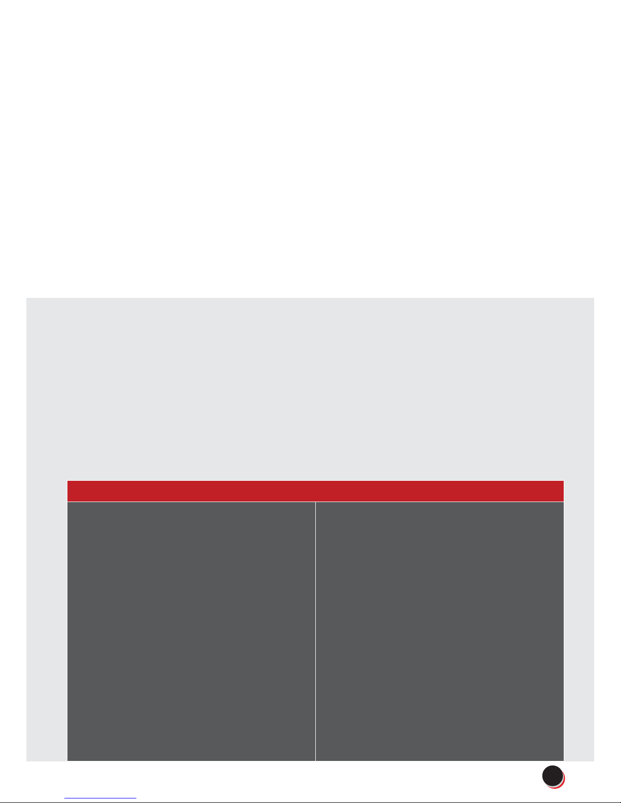
Risk of damage!
Make sure that the charging station is
not damaged by improper handling
(anchoring, housing cover, socket,
inner parts etc.).
–Do not open the lid of terminal in
the rain!
Risk of damage to housing
–Use only detergents dedicated for
anodised aluminium / plexi
–Do not tighten the mounting
screws with force.
–Electrostatically sensitive
components
Risk of damage!
–Electronic components can be
destroyed if touched!
–Before handling components,
make sure you perform an
electrical discharge by touching a
metallic, grounded object!
Installation manual ver. 1.6, © Guide 3
Information for technicians who are permitted to open the device
SmartEv Scatalo is a charging terminal for outdoor area
at which electrically operated vehicles can be charged.
Two vehicles can be charged at the same time, with 3
phases, 32A and maximum 22kW power.
The charging station is designed for installation on a
pavement mounted column.
The respective national regulations must be observed
with regard to the installation and connection of the
charging terminal.
The intended use of the device always includes the
compliance with the environmental conditions for which
this device was developed.
The device was developed, manufactured, inspected
and documented in compliance with the relevant
safety standards. Therefore, the products do not
pose any danger to the health of persons or a risk of
damage to other property or equipment under normal
circumstances, provided that the instructions and safety
precautions relating to the intended use are properly
observed.
The instructions contained in this manual must be
followed precisely in all circumstances.
Failure to do so could result in the creation of potential
sources of danger or the disabling of safety devices.
Apart from the safety instructions given in this manual,
the safety precautions and accident prevention
measures appropriate to the situation in question must
also be observed.
Only electrical vehicles or their chargers may be
connected. A connection of other loads (e.g. electric
tools) is not permitted!
5
www.smartev.co.uk | 01707 443 179
Table of contents


