manuals.online logo
Brands
  1. Home
  2. •
  3. Brands
  4. •
  5. SmartLock
  6. •
  7. Lock
  8. •
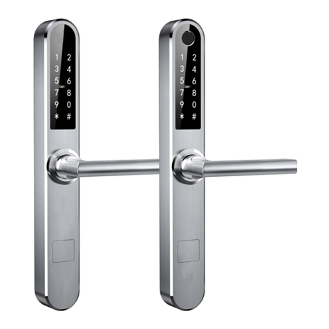
  9. SmartLock Slimline UNIVERSAL User manual

SmartLock Slimline UNIVERSAL User manual

Thank you for purchasing a Slimline UNIVERSAL smart lock. If you are tting the lock to a door with a multi-point lock
mechanism (where you lift the handle to lock) then there are two tests that should be carried out before proceeding with the
installation. The rst test is to ensure that the bolts/hooks or deadbolts fully retract when the outside handle is pulled down.
You MUST* check compatibility before drilling any holes in the door.
STEP 4
On the inside of the door, offer up the in-
ternal lock body and locate on the spindle.
Align so the lock sits straight. Hold the lock
rmly and then lift the handle fully to throw
the bolts/hooks/deadbolts. Remove the
lock body.
STEP 3
With the door open, on the door edge,
mark/observe the position of ALL the
bolts/hooks/deadbolts. The number of
locking points will vary depending on the
mechanism type.
STEP 5
Hold the keypad body and turn the spindle
receptor so that the arrow points AWAY
from the handle.
STEP 7
Check that all the bolts/hooks/deadbolts
have retracted fully back to the original
position. If they have then the lock is most
likely compatible.
Try closing the door making sure none of
the bolts prevent it from closing properly.
STEP 8
Note that the new Slimline lock may not ful-
ly cover all of the existing holes in the door.
Use the included 10mm white cover caps.
Custom colour caps are available.
COMPATABILITY TEST
TURN OVERLEAF FOR DETAILS OF THE SECOND TEST
* SmartLock Europe Ltd cannot held be liable for any damage or losses incurred by not following these instructions.
SmartLock Europe Ltd (44) 1273 930 304 [email protected].uk
STEP 1
Remove the existing handles and keyed
euro cylinder. Leave the spindle in place.
You will no longer need the euro cylinder as
the UNIVERSAL has its own key backup.
LEAVE
SPINDLE
LIFT HANDLE
HOLD FIRMLY
ARROW POINTS AWAY
FROM HANDLE
10MM COVER
CAP
STEP 2
Remove the Slimline lock from the box
and check that the handles are pointing in
the correct direction for your door setup.
If not reverse them, as per the installation
manual.
STEP 6
Offer up the keypad lock body and locate
on the spindle. Align so the lock sits
straight. Hold the lock rmly and pull the
handle fully downwards to retract the bolts/
hooks/deadbolts.
Remove the lock body, turn the spindle
receptor so that the arrow now points
TOWARDS the handle.
HOLD FIRMLY
Prefer to watch a video?
Scan the QR code or visit
https://bit.ly/slimline-univ-test
1
There are hundreds of different multi-point mechanisms and some have longer
cases. This test will check that the two xing bolts and cable can go through the
door without striking the lock case and
that the lock body will not strike the door stops or frame.
STEP 9
Remove the multi-point mechanism. It is
usually held in place by several screws down
its length.
Now follow the instructions on the enclosed installation sheet 3.
STEP 10
Fold this template down the hatched vertical
line and place it against the lock, aligning the
spindle.
Check that the lower bolt will pass through the
existing hole for the euro cylinder or below the
lock case.
Two holes are required for the top bolt and
cable. These are positioned between the two
green hatched lines. In the above example
you can see that there is space to drill two
holes without touching the lock case. In some
instances there may be an existing hole in the
lock case that can be used.
STEP 11
Finally, align the template on the door, secure
with some tape. Now close the door and make
sure that the lock outline will not strike the frame
or door stop. Repeat on the other side.
LOWER
BOLT
SPINDLE
FOLD HERE
BOLT THROUGH
EURO CYLINDER
HOLE
CLEAR SPACE
FOR 2 HOLES
CABLE
TOP
BOLT
2
SPINDLE
STEP 1
This shows an aluminium door with a
handle up multipoint lock mechanism.
In this instance you lift the handle up to
engage the deadbolts and turn the key
to lock.
STEP 2
Remove all the door hardware from both
sides of the door.
Be sure to perform the compatability test
as per the enclosed sheet before going
any further.
STEP 4
Apply masking tape to the door, fold the
enclosed paper template and align with
the spindle hole. Mark on the tape the
range for the top adjustable xing bolt.
It may be easier to drill a new hole above
the lock case for the cable.
STEP 5
Measure the position of the holes relative
to the centre of the spindle. Also measure
the overall height of the lock case. In this
instance, 55mm, 75mm & 100mm.
Mark these measurements on the mask-
ing tape.
STEP 7
Align the keypad with the spindle. Where
possible the top xing bolt should use
an existing hole in the lock case. In this
example we can use the 55mm hole.
There is no existing hole for the cable so
we will drill a new hole. Mark the cable
hole position on the masking tape.
STEP 8
Mark up the position of the holes on the
other side of the door. Double check the
positions before drilling.
STEP 9
Drill the new holes. We recommend using
a step drill for the larger holes. The rec-
ommended hole diameter sizes are:
Cable: 16mm
Top Bolt: 10mm
Spindle: 25mm - It is important to make
sure that this hole is big enough for the
split pin.
STEP 10
Drill the holes on the inside. Remove the
masking tape. Push the multi-point back
into position and secure with the screws.
Installation instructions for a
‘handle up’ multi-point lock
mechanism.
IMPORTANT
There are hundreds of different
types of multi-point lock mecha-
nism, these instructions will apply to
most but not all locks.
Before fitting, carry out the
compatibility test as detailed
in the enclosed A4 sheet.
Please use these instructions
in conjunction with the
enclosed user manual.
STEP 6
Check that the handles on the both sides
of the lock are facing the correct direc-
tion. If not, insert a Phillips screwdriver
and undo the screw, remove the handle
and ip 180 degrees, push back on and
tighten the screw. Make sure that you t
the two clear plastic washers.
STEP 3
Remove most of the screws that hold the
multipoint in place, or remove
completely. This is so you can deter-
mine the length of the lock case and the
position of any existing holes that can be
used for the xing bolts or cable.
HOLES IN
LOCK CASE
SPINDLE
ALIGN
SPINDLE
FLIP HANDLE
180 DEGREES
NEW HOLE
FOR CABLE
ABOVE
LOCK CASE
The keypad is secured by two screws
that bolt through the door. The lower
bolt will pass through the existing hole
for the keyed cylinder. The top bolt can
use an existing hole in the lock case or
a new hole can be drilled. A new hole for
the cable may be required and this can
be above the lock case or use an existing
hole. Each multi-point will be different.
LOWER BOLT
SPINDLE
TOP BOLT
CABLE
SLIMLINE UNIVERSAL
3
STEP 14
Using a Phillips screwdriver, remove the
battery cover from the internal handle set.
You may need to use the clear suction
cup. Apply masking tape to hold the
rubber gasket. Align the handle over the
spindle. Connect the cable and tuck the
white connector into the door cavity.
STEP 15
There are several machine screws of
varying lengths for different thickness
doors. Use a shorter screw through the
battery holder and a longer screw through
the bottom hole.
Do not over tighten.
STEP 16
Insert 4 x AAA batteries (not included)
Fit the cover plate and secure with the
screw. Lift the handle up to engage the
deadbolts/hooks and then pull the handle
down to make sure they retract fully.
STEP 17
Lift the handle up to engage the dead-
bolts/hooks. Using the plastic sucker,
remove the front plate. Insert the backup
key and turn, pull the handle down to
make sure that the deadbolts and latch
retract fully. Turn key back and remove.
There is USB-C connector here for
connecting an emergency power supply.
STEP 18
Remove the keys and store in a safe
place. Fit the cover plate. Remove the
protective lm from the keypad.
STEP 13
The inside of the door should look
something like this.
SmartLock Europe Ltd (44) 1273 930 304 [email protected].uk
REMOVE
PROTECTIVE
FILM
STEP 12
Offer up the keypad carefully to the door,
locating the spindle. Thread the cable
through the top hole. Make sure that the
top bolt is aligned properly, adjust if
required. The lower bolt should go
through the existing hole for the old euro
keyed cylinder.
CABLE
CONNECT CABLE &
TUCK INTO CAVITY
STEP 11
Fit the top threaded hollow rod and bolt
so it aligns with the Bolt hole. Fit the
correct length spindle and split pin. Where
the split pin goes through the spindle,
rotate so that the arrow faces the direc-
tion of the handle. Fit the lower threaded
hollow rod. Use some masking tape to
hold the rubber gasket in place.
ARROW
LOWER ROD
TOP ROD
HEIGHT
ADJUSTABLE
Now refer to step 5 in the user manual on how to connect your lock to the SMARTLOCK smartphone app.
NOTE: The Slimline lock is self locking. When you pull the door closed, it will be ‘partly’ locked on the
spring latch. To lock fully, lift the handle up from the inside or outside. A key is no longer required to lock.

Other SmartLock Lock manuals

SmartLock PREMIER - 2 USERS User manual

SmartLock

SmartLock PREMIER - 2 USERS User manual

SmartLock DEADBLOT Service manual

SmartLock

SmartLock DEADBLOT Service manual

SmartLock S31 User manual

SmartLock

SmartLock S31 User manual

SmartLock Q20 User manual

SmartLock

SmartLock Q20 User manual

SmartLock VISION User manual

SmartLock

SmartLock VISION User manual

SmartLock W-0309 User manual

SmartLock

SmartLock W-0309 User manual

SmartLock LOCKONE User manual

SmartLock

SmartLock LOCKONE User manual

SmartLock UNRD Series User manual

SmartLock

SmartLock UNRD Series User manual

SmartLock LOCK-ONE User manual

SmartLock

SmartLock LOCK-ONE User manual

SmartLock H50-TYW User manual

SmartLock

SmartLock H50-TYW User manual

SmartLock 301 User manual

SmartLock

SmartLock 301 User manual

SmartLock PREMIER User manual

SmartLock

SmartLock PREMIER User manual

SmartLock Y797 User manual

SmartLock

SmartLock Y797 User manual

SmartLock PREMIER - 10 USERS User manual

SmartLock

SmartLock PREMIER - 10 USERS User manual

SmartLock YL-73 User manual

SmartLock

SmartLock YL-73 User manual

SmartLock VISION User manual

SmartLock

SmartLock VISION User manual

Popular Lock manuals by other brands

Gantner GAT ECO.Side Lock 7010 F/ISO Installation, configuration & operation

Gantner

Gantner GAT ECO.Side Lock 7010 F/ISO Installation, configuration & operation

Sargent v.G1.5 installation instructions

Sargent

Sargent v.G1.5 installation instructions

DigitalKeys WANlock manual

DigitalKeys

DigitalKeys WANlock manual

Hafele DT 710 operating instructions

Hafele

Hafele DT 710 operating instructions

Linka LEO owner's manual

Linka

Linka LEO owner's manual

GEM gk300 Specification sheet

GEM

GEM gk300 Specification sheet

Maco MULTI-MATIC Maintenance and adjustment instructions

Maco

Maco MULTI-MATIC Maintenance and adjustment instructions

Dorma DB600 Series Instructions for installation

Dorma

Dorma DB600 Series Instructions for installation

PROMIX SHERIFF-5 operating manual

PROMIX

PROMIX SHERIFF-5 operating manual

Air TEc CYPRES user guide

Air TEc

Air TEc CYPRES user guide

effeff 495-10 operating instructions

effeff

effeff 495-10 operating instructions

Q-See QSB180 user manual

Q-See

Q-See QSB180 user manual

ALLOMATIC AML-1200 quick start guide

ALLOMATIC

ALLOMATIC AML-1200 quick start guide

Burtonsafes Keyguard XL Digital Instruction booklet

Burtonsafes

Burtonsafes Keyguard XL Digital Instruction booklet

Abus 275A quick start guide

Abus

Abus 275A quick start guide

Itec iMCODE Series quick start guide

Itec

Itec iMCODE Series quick start guide

Burtonsafes IGNIS LOCKING INSTRUCTIONS

Burtonsafes

Burtonsafes IGNIS LOCKING INSTRUCTIONS

SereneLife SLSFKEY27 user manual

SereneLife

SereneLife SLSFKEY27 user manual

manuals.online logo
manuals.online logoBrands
  • About & Mission
  • Contact us
  • Privacy Policy
  • Terms and Conditions

Copyright 2025 Manuals.Online. All Rights Reserved.