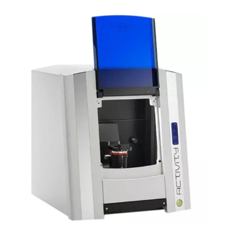
Smartoptics Activity 850 User manual

F
o
r
s
o
f
t
w
a
r
e
v
e
r
s
i
o
n
2.2.23
s
t
a
t
u
s
01
/
2012
OperatingManual
A product of smart optics Sensortechnik GmbH

1
Activity 855
Activity 850

2
Table of contents
1. LISTOFFIGURES 4
2. ICONS 5
3. GENERALSAFETYINFORMATION 5
4. TECHNICALSPECIFICATIONS 6
5. CEDECLARATIONOFCONFORMITY 8
6. GENERALSAFETYINFORMATION 10
7. INSTALLATION 12
8.1
S
ELECTING THE INSTALLATION LOCATION
12
8.2
U
NPACKING AND SCOPE OF DELIVERY
12
8.3
CARRYING POINTS 13
8.4
R
EMOVING THE SCANNER FROM THE PACKAGING
14
8. INSTALLATION 15
9.1
I
NSTALLING THE SCANNER
15
9.2
I
NSTALLING THE COMPUTER
16
9.3
I
NSTALLING THE SOFTWARE
16
9.4
I
MPORTING CALIBRATION DATA
21
9. CALIBRATIONPROCEDURE 23
10.1
A
XIS CALIBRATION
23
10.2
3D CALIBRATION 24
10. BASICINFORMATIONABOUTTHEDEVICE 26
11.1
F
UNCTIONING OF THE
A
CTIVITY
850/A
CTIVITY
855
26
11.2
INTERIOR ACTIVITY850/855 30
11.3
OBJECT HOLDER 31
11.4
POSITIONING THE MODEL ON THE OBJECT HOLDER 34
11. SCANNINGPROCEDURE 35
12.1
CLAMPING THE MODEL 35

3
12.2
C
REATING A PRESCAN
35
12.3
C
ASE STUDY
:
BRIDGE WITH BITE REGISTRATION
38
12.4
CASE STUDY: COMPLETE JAW SCAN 46
12.5
CASE STUDY: OCCLUSION SCAN49
12. SYMBOLS 56
13.1
THE SYMBOLS 56
13.2
THE 3D VIEWER SYMBOLS (OBJECT VIEW)58
13.3
ACTIVITY MENU OPTIONS 59
13.4
OPTIONS -7 SETTINGS -7 MATCHING 59
13.5
O
PTIONS
-7
S
ETTINGS
-7
G
ENERAL
60
13.6
OPTIONS -7 SETTINGS -7 INSTALLATION 63
13. MAINTENANCEANDSERVICING 64
14. FAULTSANDREPAIRS 64
15. ENVIRONMENTALFACTORSANDDISPOSAL 64
16.1
PACKAGING 64
16.2
DISPOSAL 64
16. IMPRINT 65

4
1.
List of figures
FIGURE 1 SCANNERSIDE VIEW..................................................................................................................................................... 14
FIGURE 2 SCANNER HOLDING POINT............................................................................................................................................. 14
FIGURE 3 : SCANNER HOLDING POINT........................................................................................................................................... 14
FIGURE 4 MAIN SWITCH ON THE FRONT OF THE DEVICE.................................................................................................................... 15
FIGURE 5 SETUP/INSTALLATION .................................................................................................................................................. 16
FIGURE 6 LANGUAGE SELECTION ................................................................................................................................................. 17
FIGURE 7 SETUP WIZARD .......................................................................................................................................................... 17
FIGURE 8 SELECT INSTALLATION LOCATION .................................................................................................................................... 18
FIGURE 9 START MENU............................................................................................................................................................. 18
FIGURE 10 CREATING A DESKTOP SYMBOL .................................................................................................................................... 19
FIGURE 11 INSTALLATION .......................................................................................................................................................... 19
FIGURE 12 INSTALLATION .......................................................................................................................................................... 20
FIGURE 13 COMPLETING THE INSTALLATION 20
FIGURE 14: NO CALIBRATION DATA ............................................................................................................................................. 21
FIGURE 15: FOLDER SEARCH....................................................................................................................................................... 22
FIGURE 16: SELECTED FOLDER .................................................................................................................................................... 22
FIGURE 17: IMPLEMENTING THE SENSOR DATA .............................................................................................................................. 22
FIGURE 18: CALIBRATION MODEL WITH SPACER PLATE IN ACTIVITY850............................................................................................... 23
FIGURE 19: SCAN SOFTWARE CALIBRATION........................................................................................................................... 24
FIGURE 20: SCAN SOFTWARE CALIBRATION ................................................................................................................................... 24
FIGURE 21INDIVIDUAL CALIBRATION BLOCK ................................................................................................................................... 25
FIGURE 22: CALIBRATION MODEL REGISTRATION ............................................................................................................................ 25
FIGURE 23: COMPLETING THE CALIBRATION .................................................................................................................................. 26
FIGURE 24: DEVICE FRONT ACTIVITY850...................................................................................................................................... 28
FIGURE 25: DEVICE FRONT A85 ................................................................................................................................................. 28
FIGURE 26: SIDE VIEW FIGURE 27: SYSTEM DRAWER ........................ 29
FIGURE 28: DATA PLATE........................................................................................................................................................ 29
F
IGURE
29
: R
OTATING
-
SWIVELLING UNIT
.............................................................................................................................................. 30
FIGURE 30: ROCKER/ROTATING-SWIVELLING UNIT ACTIVITY850 FIGURE 31: ROCKER/ROTATING-SWIVELLING UNIT ACTIVITY855......... 30
FIGURE 32: INDIVIDUAL PARTS OF ACTIVITY850 ............................................................................................................................ 31
F
IGURE
33
: I
NDIVIDUAL PARTS OF
A
CTIVITY
855
................................................................................................................................... 32
FIGURE 34: OBJECT HOLDER SYSTEM............................................................................................................................................ 33
FIGURE 35: OBJECT HOLDER SYSTEM WITH MODEL ......................................................................................................................... 33
F
IGURE
36
: H
EIGHT ALIGNMENT OF
A
CTIVITY
850
................................................................................................................................ 34
FIGURE 37: "NEW PROJECT"...................................................................................................................................................... 36
FIGURE 38: "NEW MEASUREMENT"........................................................................................................................................ 36
FIGURE 39: 2D SCAN AND ENTRY SCREEN ..................................................................................................................................... 37
FIGURE 40: PROMPT NOTIFICATION............................................................................................................................................. 39
FIGURE 41: DATA SET BEFORE "MATCHING".................................................................................................................................. 40
FIGURE 42: "RESCAN" MODE ..................................................................................................................................................... 41
FIGURE 43: "RESCAN".............................................................................................................................................................. 41
FIGURE 44: SAVE PROJECT......................................................................................................................................................... 42
FIGURE 45: "MATCHING" PROCESS ............................................................................................................................................. 42
FIGURE 46: “BITE REGISTRATION" SYMBOL ................................................................................................................................... 43
FIGURE 47: SQUEEZE BITE ALIGNMENT PRESCAN ............................................................................................................................ 44
FIGURE 48: CUT BITE REGISTRATION ............................................................................................................................................ 45
FIGURE 49: CUT BITE REGISTRATION ............................................................................................................................................ 45
FIGURE 50: COMPLETE JAW 2D SCAN .......................................................................................................................................... 46

5
FIGURE 51: COMPLETE JAW ALIGNMENT PRESCAN.......................................................................................................................... 47
FIGURE 52: STARTING THE SCAN PROCESS..................................................................................................................................... 47
FIGURE 53: COMPLETE JAW 3D SCAN .......................................................................................................................................... 48
FIGURE 54: 3D-STL DATA SET.................................................................................................................................................... 48
FIGURE 55: TABS................................................................................................................................................................... 49
FIGURE 56: FIXED JAW.............................................................................................................................................................. 50
FIGURE 57: ADD DENTAL SCAN ................................................................................................................................................... 50
FIGURE 58: NEW MEASUREMENT................................................................................................................................................ 51
FIGURE 59: ANTAGONIST ALIGNMENT ......................................................................................................................................... 51
FIGURE 60: PRESCAN ............................................................................................................................................................... 52
FIGURE 61: VESTIBULAR SCAN.................................................................................................................................................... 52
FIGURE 62: "ARTICULATION" ICON.............................................................................................................................................. 52
FIGURE 63: SELECT LOWER JAW FIGURE 64: SELECT UPPER JAW.................................................... 53
FIGURE 65: LOWER JAW ALIGNMENT ........................................................................................................................................... 54
FIGURE 66: "NEXT" ................................................................................................................................................................. 54
FIGURE 67: UPPER JAW ALIGNMENT ...................................................................................................................................... 54
FIGURE 68: ALIGNED UPPER AND LOWER JAWS ..................................................................................................................... 55
F
IGURE
69
: A
RTICULATED
STL
DATA SET
..............................................................................................................................................55
FIGURE 70: ACTIVITY MENU OPTIONS.......................................................................................................................................... 59
F
IGURE
71
: S
ETTINGS
- M
ATCHING
..........................................................................................................................................................59
FIGURE 72: SETTINGS - GENERAL.......................................................................................................................................... 60
FIGURE 73: SETTINGS - INSTALLATION .................................................................................................................................. 63
2.
Icons
This symbol indicates warning information
Useful hints are marked with a light bulb in the operating manual
3.
General safety information
Proper use:
The Activity 850 and Activity855 scanners are intended for use in performing optical, three-
dimensional measurements of human jaw models.
It is possible to measure articulated models in order to simulate masticatory movements using
correspondingsoftware, asin an articulator.
Anything other than the proper use is strongly advised against, as improper use may cause
damageorinjury.
Pictures and screenshots may vary depending on the Scanner model Activity850 or Activity855
.

6
4.
Technical specifications
Activity850
Activity855
Axis
3
2
Dimensions
440 mm x 480 mm x 430 mm
(WxHxD)
440 mm x 480 mm x 430 mm
(WxHxD)
Weight
34 kg
33 kg
Connection voltage
100-240 V AC, 50-60 Hz
100-240 V AC, 50-60 Hz
Powerconsumption
80 W
80 W
Protection class
IP11
IP11
Permissibletemperature
range
18-30°C
18-30 °C
Measureable objects
Plaster models of teeth
Plaster models of teeth
Minimum clamping range
of the removable object
holder
40 mm
40 mm
Maximum clamping range
of the removable object
holder
70 mm
70 mm
Height adjustment
+/- 20 mm
//
Measuring time for the
measurement of
Singlestump:<60sec./unit
3-bridge:< 90sec.
Completejaw:<180sec.
Singlestump:<55sec./unit
3-bridge:< 90sec.
Completejaw:<90sec.
Resolution
Basic resolution of the 3D
sensing head: 50 µm
Scanfield:50x 66 x 50mm(x,y,z)
Basic resolution of the 3D
sensing head:62,5 µm
80 x 60 x 85 mm(x,y,z)
Accuracy
+/-10µmstandarddeviation
measured at test specimen,
determinedviamin.50
measuring points with 10
repetitions each
Accuracy according to
DIN ISO 12836 6
µm
Implant bar accuracy
(following DIN ISO 12836,
messured distance 50.8 mm)
8
µm
Output data format
STL
STL
Interfaces
USB
USB
Scope of delivery
Scanner, power cord, 2x USB
cable, CD with operating
software and calibration data,
Scanner, power cord, 2x USB
cable, CD with operating
software and calibration data,

7
operating manual, calibration
block
operating manual, calibration
block
System requirements
Operating system Windows 7
Ultimate 64® Bit, Intel core 2
Quad CPU Q 9550 2.83 Ghz or
higher,RAM8GB,high-
performance 3D graphics card
with min.1GB RAM e.g.
GeForce, 320 GB hard disk
Operating system Windows 7
Ultimate 64® Bit, Intel core 2
Quad CPU Q 9550 2.83 Ghz or
higher,RAM8GB,high-
performance 3D graphics card
with min.1GB RAM e.g.
GeForce, 320 GB hard disk

8
5.
CE declaration of conformity

9

10
6.
General safety information
When setting up, commissioning and operating the scanner, you must observe the following
safetyinformationatalltimes.
1.
The devicemay be operated only by adequately trained staff who have knowledge
concerning the proper use of the device as well as the safety information cited here.
2.
The device is intended exclusively for use in dry, enclosed rooms.
3.
The device may be operated only on a stable base (tabletop, bench, etc.) that has a load
bearing capacity which is at least twice the net weight of the scanner as stated in the
technical specifications.
The base must be fixed to a building wall or have a braced support frame that is suitable for
absorbingvibrationsoccurringduringoperationofthescanner.
Besides the pure load-bearing capacity, the sturdiness and stability of the base is crucial for
safe operation of the scanner.
4.
The information on transport and storage must be observed when lifting and transporting the
scanner.
5.
Please do not place any objects on the scanner, as there is a risk that these can fall down
owing to the surface structure as well as the resultant vibrations during scanning operation.
6.
The "Activity 850" and “Activity 855” scanners has been developed and manufactured in
accordance with the applicable safety standards and with the greatest possible care. In spite
of this, the risk of an electric shock, overheating or fire due to technical defects in individual
components cannot be totally excluded.
You should therefore switch the device off when not using it for longer periods and when it
is left unattended. This also benefits the environment, as it means less electrical energy is
consumed.
7.
Thescannercontains a motionunit comprisingthreeelectrically powered axesof rotation
that serve to position the object during scanning.
To enable the object to be clamped in a definite position as well as a faster workflow during
scanning, the movement axes are also kept in position electrically when the flap is open.
Anelectronicprotectionmechanismpreventsthe motorsfromstartingupunintentionallyor

11
continuing to operate when the flap is opened.
As there is a theoretical possibility of the protection mechanism failing, this entails a residual
risk which you can counter by complying with the following rules of use:
7.1.
Do not open the front flap during a scanning procedure until after
a corresponding prompt or the end of a scanning procedure has been displayed on the
screen.
7.2.
If you determine that the scanner is acting unusually, such as an uncontrolled or continuous
rotation of one or more movement axes, switch off the scanner at the main switch before
opening the flap.
If this unusual behaviour continues after switching on again and restarting the software, do
not use the scanner any longer. The device must be marked as defective and prevented from
beingputinto operationagainuntilthefault is rectified.
7.3.
Do not reach inside the scanner if one or more movement axes move despite the flap being
open. Switch the scanner off immediately.
The scanner may no longer be used in this case and must be marked as defective and
preventedfrom beingputintooperation againuntilthe faultisrectified.
7.4.
During scanning, never reach below the area between the rocker and case that is marked by
warningsigns.
This also applies if the rocker is swivelled upwards to the rear.
Before removing any objects that have fallen into the scanner or before cleaning the scanner
compartment, you must switch off the device at the main switch.
8.
If you notice that the scanner is damaged or defective, you must label it as defective and
make sure that it is not used until it has been repaired.

12
7.
Installation
8.1
Selecting the installation location
Before installing the scanner, you should select a suitable installation location.
A suitable, stable base (bench, tabletop etc.) should be chosen as an installation location.
If you install the computer required for operating the scanner underneath the worktop, the
available worktop area should be at least 1.1m x 0.75m (front width x depth). If you planto also
place the computer on the worktable, the area must be enlarged corresponding to the dimensions
of the computer.
Theselected workplaceshould,ifpossible,face awayfromwindows or strongartificial light,as
excessively strong external light can lead to undesirable reflections onthe monitor thatcan
interfere with the functioning and results of the optical scanner in extreme cases.
8.2
Unpacking and scope of delivery
Inspect the external packaging for visible damage as soon as you take delivery of the scanner. If
you notice that the packaging is damaged, inform the delivering forwarder and your specialist
dealer immediately.
The device is delivered in a strong outer box on a wooden pallet. After removing the straps, open
the upper folding lid of the box. The box contains a foam piece that protects the scanner, which is
packed below duringtransport.
First, pull the foam pieceupwards out of the box.You can then lift off the whole box upwards.
The net weight of the scanner is approx. 33 kg.
Alwaysobservethe followinginstructions to liftthe scannerproperlyoutofthe
packaging and position it at its location of use.
Y
Two people must lift the device out of the packaging and place it on the prepared,
intended workplace.
Y
Be sure to transport the scanner (while still on the pallet) as closely as possible to the
workplace toavoid longertransport distances.
The scanner accessories can be found at the base of the packaging.
Check that the scope of delivery is complete.

13
Scope of delivery
Activity850
Activity855
1 scanner
X
X
2USBcabels
X
X
1 hex key
X
X
1 user manual in PDF format
X
X
1 calibration object
X
X
1 software installation CD including calibration data
X
X
1 removable object holder
X
X
1 measuring range template
X
1 spacer plates 10mm
X
8.3
Carrying points
Carrying points are provided to move the device. Please note these specifications.
Stand so that one person each is positioned to the left and right of the scanner. Take hold of the
scanner with one hand at the bottom front of the scanner and the other hand at the top rear. In
this way, the scanner can be safely tilted slightly to the rear.
Carrying points, rear
(back of the device)
Person A Person B
Carrying points, front
Never carry the scanner with the flap open, and do not carry the scanner using the flap
itself.

14
8.4
Removingthe scannerfrom the packaging
1.
To remove the scanner from the packaging, one person stands to the left of the scanner and
the other person stands to the right.
2.
Each person must take hold of the scanner with one hand on the upper support point. Next, tilt
the scanner slightly to the rear until you can grip underneath the scanner at the front with your
otherhand.(Figures2and3)
3. Working together and at the same time, lift the scanner out of the packaging and place it at
theinstallationsite.
4.
When doing do, make sure that you have free access to the workplace and do not trip over the
packaging.
Remove the upper
part of the packaging
Figure 1 scannerside view
Gripand tilt the scanner
at the upper holding point
(one holding point each side for
each person).
Figure 2 Scanner holding point
Lift the scanner at the same time
and place it at the installation site.
Figure 3 : Scanner holding point

15
8.
Installation
9.1
Installingthescanner
Please make sure that the mains switch is at the "0" position before installation. (The position of
the main switch maybe different)
Figure 4 Main switch on the front of the device
1.
Connect the device to the USB cables using the USB ports on the rear of the device.
Functional earth Fuse USB camera
USB device control
Mains connection

16
2.
Connect the other ends of the USB cables to USB connections on the rear of your
computer.
3.
Connect the scanner to a power source via the mains connection on the rear.
4.
Now switch the scanner on at the mains switch.
5.
Now first switch the scanner off again and continue by installing the computer and
operating software.
9.2
Installingthecomputer
Installthecomputerfollowingtheinstallationinstructionsofthecomputermanufacturer.
9.3
Installingthesoftware
As each scanner has been calibrated individually at the factory, the data on the
installationCDisvalidonlyforthecorrespondingscanner.Thiscalibrationdata
contains a code that can be enabled only by the corresponding scanner. Therefore,
compare the serial number indicated on the data plate of the scanner with the serial
number indicated on the CD to make sure they match before installation.
If you have mistakenly installed an incorrect version of the software, you must uninstall the
incorrect version first.
If you are installing the Activity software on your computer for the first time, use the installation
CD provided with the scanner.
A window will open after inserting the CD. The "Setup" icon opens and must be selected to start
the installation.
Figure 5 Setup/Installation

17
Now select the required language (Fig. 6) and confirm your selection with the "Next" icon (Fig. 7).
Figure 6 Language selection
Figure 7 Setup Wizard
Define the installation location for the software by using the "Browse" button to define the path.
The installation program suggests a standardized path that you can use. Having selected the path,
please confirm this with "Next".

18
Figure 8 Select installation location
Define the software name in the "Select Destination Location Folder" window.
Thenclickon"Next".
Figure 9 Start Menu
Select whether you require a Desktop symbol and confirm with "Next".

19
Figure 10 Creating a Desktop symbol
Before starting the installation, check your selected settings and chose "Next". The installation
starts immediately (Fig. 11).
Figure 11 Installation
Other manuals for Activity 850
1
This manual suits for next models
1
Table of contents
Other Smartoptics Scanner manuals
