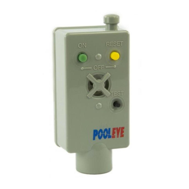
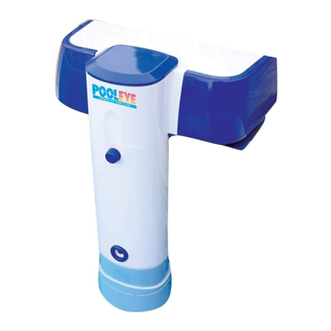
SmartPool Pooleye PE20 User manual

PE20MAN-REV 01.032018
®
MODEL NO. PE20
OWNER’S MANUAL

2PE20MAN-REV 01.032018
IMPORTANT: READ THOROUGHLY PRIOR TO INSTALLING AND OPERATING
THE POOLEYE ALARM.
TABLE OF CONTENTS
Important Safety Information ..........................................................................................2
List of Components ..........................................................................................................3
Installation......................................................................................................................3
Winterization...................................................................................................................7
Troubleshooting...............................................................................................................7
Warranty.........................................................................................................................8
Read all instructions prior to installing or operating this device.
Failure to follow the instructions may result in injury or death.
This product does not replace the need for adult supervision of all persons in the pool area.
This product is not a life saving device but an aid to a multi-level program of pool safety including
adult supervision, knowledge of CPR and swimming instruction for all persons using the pool.
This product is intended for use on residential pools only, and the manufacturer assumes no respon-
sibility for injuries or consequential property damage while this product is in use on a swimming pool.
Proper installation and maintenance are the sole responsibility of the pool owner.
Do not permit children to use this product unless closely supervised by an adult at all times.
Do not operate this product unless it is submerged in water.
Do not use this product if it is damaged in any way.
Never leave children unattended near or in the pool.
It is imperative to react quickly once the alarm has sounded.
Swimming instruction is recommended for those who cannot swim.
Participation in a safety instructional course such as CPR (especially for children) is recommended.
For children or persons that cannot swim, a Personal Floatation Device (PFD) is recommended
when entering the pool area.
Test the alarm weekly to ensure it is working properly.
Do not leave toys or objects floating in an unattended pool as this may invite children to enter the pool.
eep the pool water clear so all objects on the bottom of the pool are visible.
Layers of protection add to the security of the pool. A barrier fence should always be used around a
pool in conjunction with a gate or door alarm, such as SmartPool’s YardGard to alert the responsible
party that an unwanted intrusion to the pool area has occurred.
!
IMPORTANT SAFETY INFORMATION
WARNING:
!
WARNING:
!
WARNING:
!
WARNING:
!
WARNING:
!
WARNING:
!
WARNING:
!
WARNING:
!
WARNING:
!
WARNING:
!
WARNING:
!
CAUTION:
!
CAUTION:
!
CAUTION:
!
CAUTION:
!
CAUTION:
!
CAUTION:
!
IMPORTANT:

3 PE20MAN-REV 01.032018
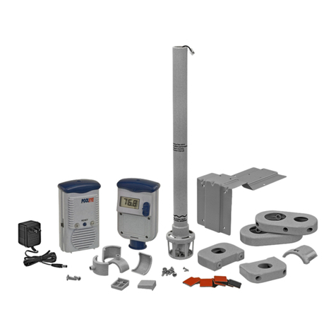
LIST OF COMPONENTS
ITEM DESCRIPTION QTY
A Alarm Body 1
B Mounting Plate 1
C Siren 1
D Plate Bracket 2
E Ladder Mount Clamp 2
F Plate Shim Screw 2
G Self Tapping Screw (Ladder Mount) 6
H Machine Threaded Screw (Deck Mount) 4
I Adhesive Pad (sets) 4
J Plate Shim 2
Ladder Shim 4
L Deflector Shield 1
EQUI ED TOOLS/MATE IALS
• Phillips Head Screwdriver (#2)
• (1) 9 VDC Battery
• Concrete Sealant/Paint (optional)
• Wood Deck Screws (optional)
INSTALLATION
POSITIONING OF THE ALA M
ey factors for proper alarm positioning:
1) Direction of the return line water flow.
2) Distance of the alarm from all points of the pool.
• The eyeball of the return line must be facing a
downward direction as to not disturb the
surface of the water.
CORRECT INCORRECT
• Ensure that the eyeball of the return is not facing the
center of pool but is either creating a clockwise or
counterclockwise water flow.
IMPORTANT: Larger pool sizes and/or pool shapes may require the use of more than one alarm. Testing the alarm
from all areas of the pool is essential to ensure the alarm will activate regardless of the entry point.
RETURN RETURN
ALARMALARM
ound Shaped Pools
• Ensure the alarm is centrally located for the
shortest distance to all points of the pool.

4PE20MAN-REV 01.032018
ALARM
ALARM
Oval or Rectangle Pools
WARNING: Every pool is different. The alarm must be tested immediately upon installation to ensure the positioning
of the alarm fits its specific environment. Improper positioning of the alarm or return fitting may result in false alarms.
ALARM ASSEMBLY
1. Remove the 4 screws of the battery casing on the
alarm siren (Fig 1).
2. Install a new 9Vdc battery and reinstall battery casing.
3. Plug the Alarm Body into the Alarm Siren by
connecting the cable (Fig 2).
4. Coil the wire inside the Alarm Body and then fit the
Alarm Siren onto the Alarm Body, pressing gently into
place.
5. Press and release the black Test button on the front of
the alarm to ensure the siren is sounding (Fig 3).
WARNING: If siren does not sound, check that the
Alarm Body connection from Step 3 is secure and retest.
If issue persists, please see the warranty section of the
manual for Technical Support contact information.
MOUNTING THE ALARM
IMPORTANT: There are two options for mounting the
alarm to the pool. Choose the best option for the specific
design of the pool to ensure full protection of the pool.
IMPORTANT: The alarm must be installed vertically, so
that the Float is directly aligned with the Alarm
Body/must run parallel with the pool wall.
IMPORTANT: When installing the alarm, ensure the
Sensor Float is parallel with the pool wall prior to
tightening the clamps.
IMPORTANT: Ensure the sensor is at the minimum
depth requirement as indicated on the alarm body prior
to tightening the clamps.
Fig 1
Fig 3
Fig 2

5 PE20MAN-REV 01.032018
1. Using the "W" shaped Ladder Mount Clamps, place
(1) clamp around the alarm and the top, vertical
portion of ladder, ensuring a tight fit around the
ladder. If the clamp is loose around the ladder, insert a
set of Ladder Shims to tighten the fit around the
ladder (Fig 4 & 5).
2. Use the self tapping screws and loosely secure the
clamp to the ladder and alarm.
3. Maneuver the Alarm Body to ensure the sensor depth
and Sensor Float are correctly positioned as indicated
on the Alarm Body (Fig 10).
4. Install the second clamp further down the ladder to
support the alarm.
1. Identify the location of the where the alarm will be
installed.
2. Using a water-proof paint/concrete sealer, paint the
area where the alarm will be installed that is 1" wider
and longer than the metal Mounting Plate (Fig 6).
3. Loosely attach the Alarm Body to the Mounting Plate
using the machine-threaded screws and the "U"
shaped Plate Brackets (Fig 7).
4. After the area dries, place the alarm in the installation
area and confirm that the Alarm Body is parallel with
the pool wall. If the Mounting Plate needs to be
leveled, use the (2) Plate Shims to level the
Mounting Plate by securing to the back of the plate
with small screws provided (Fig 8).
5. Attach the adhesive pads to the corners of the
Mounting Plate (Fig 9).
6. Center the Mounting Plate in the installation area and
press the plate down firmly to secure it to the deck.
7. Maneuver the Alarm Body to ensure the sensor depth
and Sensor Float are correctly positioned as indicated
on the Alarm Body (Fig 10).
8. Tighten the screws to the Mounting Plate to secure the
Alarm Body.
IMPORTANT: Check Sensor Float positioning, sensor
depth and ensure the Alarm Body is parallel with the pool
wall (vertical).
LADDE MOUNT
DECK MOUNT (CONC ETE)
Fig 4 Fig 5
IMPORTANT: Check Sensor Float positioning, sensor
depth and ensure the Alarm Body is parallel with the pool
wall (vertical).
Fig 6
Fig 8 Fig 9
Fig 7
Fig 10

IMPORTANT: Press the TEST button on the front of
the alarm siren everytime the alarm is turned to the ON
position to ensure the batteries are operational.
IMPORTANT:
Test the full alarm function once every week.
IMPORTANT: Change the batteries of the alarm at
least once every swim season and immediately if siren is
not sounding during testing or if siren seems to be
operating at a lower volume.
1) Ensure the surface of the pool water is calm.
2) Turn the alarm to the ON position.
3) Fill a 5 gallon bucket 1/3 of the way with water.
4) Drop the bucket into the pool from a height of 6
inches (Fig 14).
NOTE: The wave created from the bucket will travel at
4ft per second to reach the alarm.
5) Once the alarm sounds, turn the alarm OFF and wait
for the water to settle before turning the alarm back
to the ON position.
6) Repeat the test from various points of the pool to
ensure the alarm is operating correctly.
IMPORTANT: If the siren does not sound when the
wave created by the bucket reaches the alarm, please
see the troubleshooting guide for assistance. If the siren
sounds prior to dropping
the bucket into the
water, please refer to
following section entitled
ADJUSTING THE ALARM
SENSITIVITY.
6PE20MAN-REV 01.032018
OPE ATING THE ALA M
• To turn the alarm ON, press and release the green
button. A beep will be heard (Fig 11).
• To turn the alarm OFF, press and hold both the green
and yellow buttons until the siren beeps 3 times (Fig 12).
WARNING: The alarm will not alert you if someone
enters the pool while in the OFF position.
• To RESET the alarm after the siren has altered to water
entry, press and release the yellow RESET button (Fig 13).
NOTE: The alarm may continue to sound after the RESET
button has been pressed if the water has not settled.
TESTING THE ALA M
DECK MOUNT (WOOD DECKING)
1. Identify the location of the where the alarm will be
installed.
2. Loosely attach the Alarm Body to the Mounting Plate
using the machine-threaded screws and the "U"
shaped Plate Brackets (Fig 7).
3. Place the alarm in the installation area and confirm
that the Alarm Body is parallel with the pool wall. If
the Mounting Plate needs to be leveled, use the (2)
Plate Shims to level the Mounting Plate by securing to
the back of the plate with small screws provided (Fig 8).
4. Use deck screws (not included) to fasten the bracket
securely to the deck.
5. Maneuver the Alarm Body to ensure the sensor depth
and Sensor Float are correctly positioned as indicated
on the Alarm Body (Fig 10).
6. Tighten the screws to the Mounting Plate to secure
the Alarm Body.
.
IMPORTANT: Check Sensor Float positioning, sensor
depth and ensure the Alarm Body is parallel with the pool
wall (vertical).
Fig 11
Fig 13
Fig 12
Fig 14

7 PE20MAN-REV 01.032018
ADJUSTING THE ALA M SENSITIVITY
NOTE: Alarm is factory-set to the highest sensitivity level.
1) Loosen the screws on the bottom of the sensor tube
(Fig 15).
2) Slide the adjustment switch from the high
sensitivity position (H) to the low sensitivity
position (L) (Fig 16).
3) Tighten the screws on the bottom of the sensor
tube to complete the adjustment.
4) Test the alarm to ensure it is performing properly.
ADJUSTMENT SWITCH
DEFLECTOR SHIELD
The deflector shield can be used to lower the sensitivity
of the alarm in cases where the water flow from the
return is setting off the alarm.
1) Snap the shield onto the sensor cage facing the
direction of water flow (Fig 17).
2) Retest the alarm to ensure it is performing properly.
WINTE IZATION
1. Remove the alarm from the pool.
2. Dry the alarm thoroughly.
3. Remove the battery.
4. Store in a dry location that is above the freezing point.
T OUBLESHOOTING
Fig 15
Fig 16
Fig 17
SYMPTOM REASON SOLUTION
Alarm Not
Sounding
Low Battery Install new batteries
Alarm not activated Ensure the main switch is turned to the ON position
Connection not secure Ensure the connection between the siren and alarm body is secure
Sensitivity is set on L or Low Ensure the sensitivity is set to H or High
Sensor shield blocking wave Remove sensor shield from sensor cage
Alarm too deep Raise the floating sensor closer to the surface of the water
Alarm
Constantly
Sounding
Alarm too shallow Lower the floating sensor further into the water
Sensitivity is set on H or High Adjust the sensitivity to L or Low
Connection lost after alarm
turned ON Ensure the connection between the siren and alarm body is secure
Return water flow setting off
alarm Adjust the return eyeball to face down or away from the alarm

8PE20MAN-REV 01.032018
SIX MONTH LIMITED WARRANTY
Six month limited warranty from date of original purchase for manufacturing defects under normal and reasonable use, and
subject to the maintenance requirements and installation guidelines set forth in the product instruction manual.
THIS WARRANTY IS SUBJECT TO THE TERMS, LIMITATIONS AND EXCLUSIONS DESCRIBED
BELOW, AND THERE ARE NO OTHER WARRANTIES OR REPRESENTATIONS, EITHER
EXPRESS OR IMPLIED, WHETHER OF MERCHANTABILITY, FITNESS FOR A PARTICULAR
PURPOSE, OR OTHER, MADE BY THE MANUFACTURER, OTHER THAN THOSE SPECIFICALLY
SET FORTH IN THIS WRITTEN WARRANTY
What is Covered: SmartPool LLC warrants its electronic prod ct to be free from defects in material and
workmanship when leaving the factory.
What is not Covered: Any type of damage to the prod ct d e to improper installation, maintenance, or fail re
to provide necessary and reasonable maintenance; any damage or inj ry ca sed by mis se and/or nreasonable
se of the prod ct; batteries (if applicable); damage d e to or related to improper draining, winterizing, storage
or Acts of God; SmartPool LLC will not honor any claims for damage to any prod cts in transit nless damage
to the shipping container is noted at the time of delivery on the transfer company’s delivery bill.
THE WARRANTY OBLIGATIONS OF SMARTPOOL LLC ARE LIMITED TO REPAIR OR REPLACEMENT OF THE
PRODUCT OR OF ANY DEFECTIVE COMPONENT, AT THE OPTION OF SMARTPOOL. UNDER NO
CIRCUMSTANCES WILL SMARTPOOL LLC BE LIABLE OR RESPONSIBLE FOR ANY CONSEQUENTIAL OR
INCIDENTAL DAMAGES, AND/OR CHARGES FOR LABOR. SMARTPOOL SHALL NOT BE LIABLE OR
RESPONSIBLE UNDER ANY CIRCUMSTANCES OR ANY AMOUNT FOR ANY CONSEQUENTIAL OR INCIDENTAL
DAMAGES, OR FOR ANY INJURIES OR DAMAGES TO PERSON OR PROPERTY USING OR USED IN
CONNECTION WITH THE PRODUCT, OR FOR ANY OTHER LOSS OF PROFITS OR OTHER COSTS OR
EXPENSES OF ANY KIND OR CHARACTER. IF SMARTPOOL LLC DETERMINES THAT EITHER REPAIR OR
REPLACEMENT OF THE PRODUCT IS NECESSARY, SMARTPOOL MAY EITHER REPAIR THE PRODUCT AT A
NOMINAL CHARGE TO THE OWNER OR REPLACE THE PRODUCT. THE OWNER BEARS THE SOLE
RESPONSIBILITY FOR PRE-PAID RETURN OF THE PRODUCT TO SMARTPOOL, AND ALL REPAIRED OR
REPLACED PRODUCTS WILL BE RETURNED AT THE OWNER’S EXPENSE.
NO PERSON, FIRM, OR CORPORATION IS AUTHORIZED TO MAKE REPRESENTATIONS OR INCUR ANY
OBLIGATIONS IN THE NAME OF OR ON BEHALF OF SMARTPOOL LLC, EXCEPT AS STATED HEREIN. THE
REMEDIES SET FORTH IN THIS WARRANTY ARE EXPRESSLY UNDERSTOOD TO BE THE EXCLUSIVE
REMEDIES AVAILABLE TO THE OWNER, AND THIS WARRANTY CONTAINS THE FULL AND COMPLETE
AGREEMENT BETWEEN SMARTPOOL LLC AND THE OWNER. THIS WARRANTY SETS FORTH THE ONLY
OBLIGATIONS OF SMARTPOOL LLC, WITH REGARD TO THIS PRODUCT, AND THERE ARE NO WARRANTIES
WHICH EXTEND BEYOND THE DESCRIPTION ON THE FACE HEREOF.
The representations set forth herein are the only representations made by SmartPool LLC, with respect to the product, and this warranty does not
constitute either a performance or satisfaction guarantee. It is the responsibility of the product owner to regularly test and check the product for
proper function and safety.
This warranty gives the original owner specific legal rights. You may have other rights depending on where you live.
What you must do to file a laim: Contact Technical Support at 732-730-9880, M-F, 9am-5pm EST.
Other manuals for Pooleye PE20
1
Table of contents
Other SmartPool Security System manuals
Popular Security System manuals by other brands

INIM
INIM IC0020 Series manual

ERA
ERA Protect Replica Siren Installation and operating manual

Bosch
Bosch ISW-BKF1-H5X installation instructions

ELRO
ELRO DWH SERIES Nstallation and operation instruction manual

Whelen Engineering Company
Whelen Engineering Company Super-LED L32-Series installation guide

Skov
Skov DOL 2300 Technical user guide