manuals.online logo
Brands
  1. Home
  2. •
  3. Brands
  4. •
  5. WAREMA
  6. •
  7. Controllers
  8. •
  9. WAREMA LONMPM 8DI User manual

WAREMA LONMPM 8DI User manual

1
warema_890416_alhb_en_v2•2022-10-01 We reserve the right to make technical modifications
WARNING
It is important to comply with the following
points of instruction in the interest of per-
sonal safety.
Children may not play with the operating elements of
the control unit or the remote control. Store the remote
controls out of reach of children.
Make sure that no persons or objects are in the range
of movement of the driven parts (blinds, external vene-
tian blinds, etc.).
Disconnect the device from the supply voltage if clean-
ing or other maintenance work must be performed.
Information on the electrical installation
An on-site overload current disconnecting and isolating
switch to switch off the entire system must be provided.
Installation
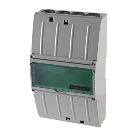
The motor control unit is, depending on the selected meth-
od of installation, designed for surface mounting (AP) or for
installation in a distributor (REG).
There are two ID labels (Fig. 2) inside the device. If you are
setting up a complex unit, pull off one of the labels and af-
fix it to your wiring diagram. This measure ensures that the
device can be identified without any mistake in the event of
a later integration.
6
123 7
84
5
Fig. 2 LONMPM 8DI/8DO Inside view with barcode labels
1 4-fold encoding switch
2 8-fold encoding switch
3 Power LED
4 Service push button
5 Service LED
6 Status LED
7 LEDs: channel 1...8 + manual
8 ID label
General information
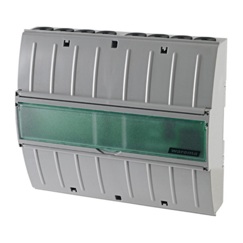
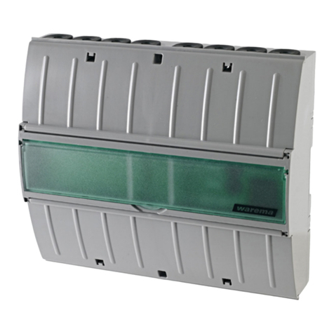
Fig. 1 LONMPM 8DI/8DO
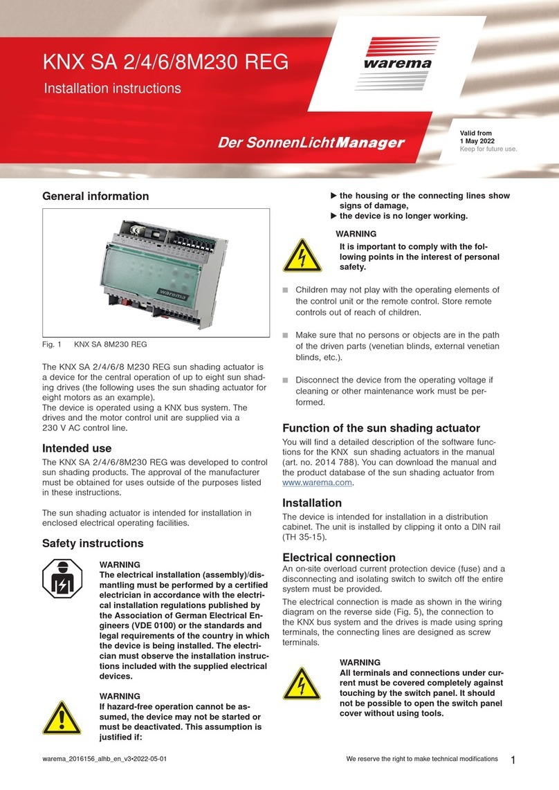
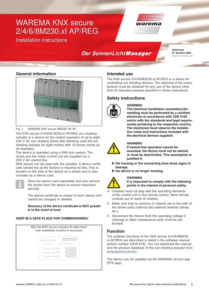
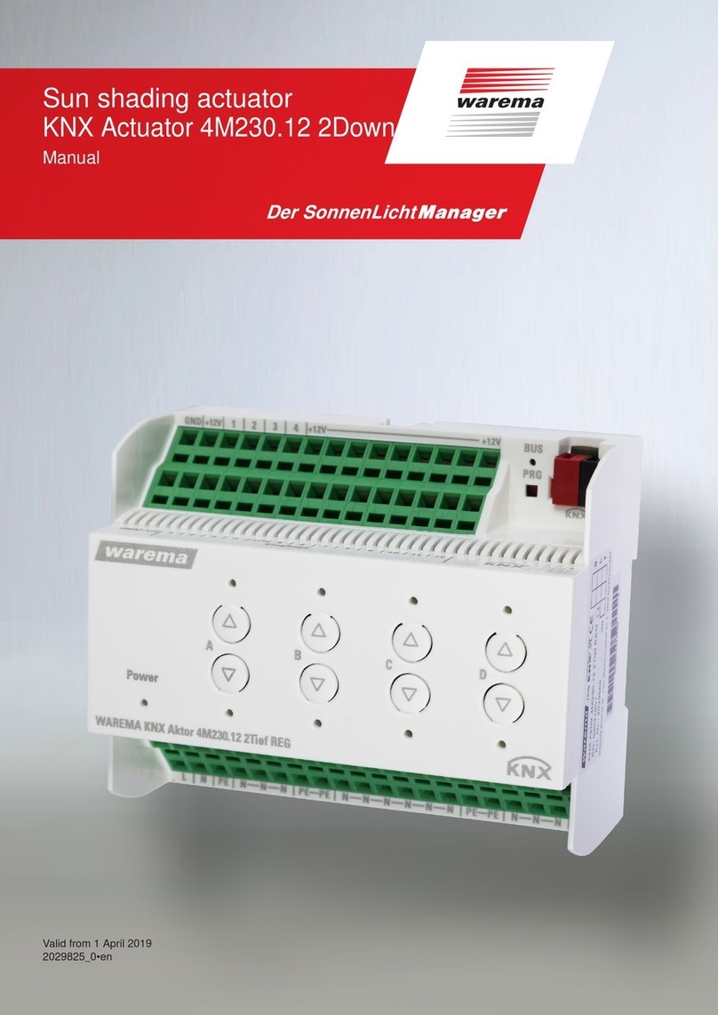
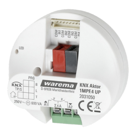
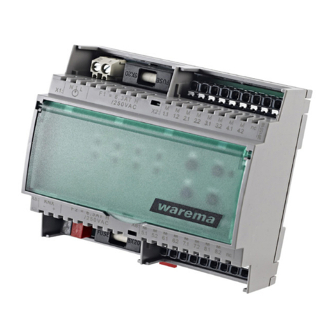
The LONMPM 8DI/8DO actuator is a multifunctional mod-
ule for various control tasks. It can read in 8 floating switch-
es, push buttons or other contacts. Eight floating make
contacts are available at the control outputs. Depending on
the software in use, this module can be used for control-
ling lighting systems, monitoring window contacts and oth-
er control tasks.
Intended use
The LONMPM 8DI/8DO actuator was developed for the con-
trol of lighting, heating, cooling and ventilation units. The ap-
proval of the manufacturer must be obtained for uses out-
side of the purposes listed in these instructions.
Safety instructions
WARNING
The electrical installation (assembly)/dis-
mantling must be performed by a certified
electrician in accordance with the electri-
cal installation regulations published by
the Association of German Electrical En-
gineers (VDE0100) or the standards and
regulations of the country in which the
device is being installed. The specialist
must observe the installation instructions
included with the electrical device.
WARNING
If hazard-free operation cannot be as-
sumed, the device may not be started or
must be deactivated. This assumption is
justified
 If the housing or the supply lines show signs
of damage,
 The device is no longer working.
Valid as of
1 October 2022
Keep for future use.
LONMPM 8DI/8DO
Operating and installation instructions
warema_890416_alhb_en_v2•2022-10-01We reserve the right to make technical modifications
2
Surface-mounted housing
Insert a slotted screwdriver (recommendation: 3.0 - 4.0
mm blade) into the respective cover opening (see Fig.
6) and carefully pry the folding cover open. Repeat the
procedure for the second opening of the cover. The
cover can be raised when both catches have been
released. The second cover can be opened in the same
manner. Alternatively, the surface-mounted variant can
be mounted on a DIN rail (TH 35-15). This device type
is not suitable for use in damp locations.
DIN rail-mounted housing
When installing the device in a distributor, clip it onto
a symmetrical DIN rail (TH 35-15). To ease connec-
tion of the device, the terminal covers can be removed
(see Fig. 3). One of the terminal covers can be re-
moved to connect the network.
Remove the terminal covers:
Insert a suitable screwdriver
into the notch.
Fig. 3 Loosening the terminal covers (DIN rail variant)
In the surface-mounted version, an optional strain relief set
is available:
Fig. 4 Strain relief set for AP housing
Commissioning
Function test: Before applying the operating voltage,
ensure that all 12 encoding switches are in the OFF posi-
tion (see Fig. 2). After the operating voltage is applied, the
device is ready for operation and its basic functions can be
checked without being connected to the network. See also
Fig. 2.
Some operating elements or LEDs are only visible
with the housing cover open.
Correct functioning after the supply voltage is switched on
is indicated when
The service LED (5) briefly lights up green
The red "manual" LED (7) lights up red for approx. 1
second
The power LED (3) lights up green permanently.

Manual operation/emergency operation: The encoding
switches 1...8 (S3) are allocated to the respective switching
channels 1...8. Individual channels can be preselected by
flipping individual switches. For example, slide control no.
1, 2, 6 and 7 of switch S3 in Fig. 5 are in the ON position.
1234
ON
1234
ON
5678S3 S2
Fig. 5 Encoding switches S2 and S3
If slide control no. 4 on the encoding switch (S2) is then
moved to the ON position as well, the previously selected
channels are switched. At the same time, the associated
channel LEDs and the "manual" LED light up.
These switches may only be used for emer-
gency operation and testing. The switches
may not remain in the ON position during
normal operation.
Testing the switching contacts connected to the input
side: Binding must not yet have occurred at this point.
When the connected push buttons are actuated, the cor-
responding relay will pull in. The associated channel LED
must light up at the same time. This can also take place
without commissioning the network.
Make sure first that manual operation cannot
cause any damage to the devices connected
to the output side. Mutual locking of indi-
vidual channels, as may be available in future
software version, is not available in this test
mode. Incorrect operation could therefore
destroy connected power consumers. For
example, you cannot have a drive run on level
1 and level 2 at the same time.
Take suitable precautions to prevent damage due
to electrostatic discharge.
However, to centrally operate the system and set up the
comfort and safety functions, the LONWORKS®network
must be put into operation. The description can be found in
the software documentation of your control unit. Please ask
your system integrator for details.
Maintenance
There are no parts within the device that require mainte-
nance.
The device contains overheating protection that in-
terrupts the power supply if the operating tempera-
tures rise to an impermissible level. Overheating of
the device indicates a fault. Switch off the unit and
check that it has been installed correctly.
Cleaning
Clean the housing with a soft, dry cloth. Do not use deter-
gents, cleaning agents, solvents, abrasive substances or
steam cleaners!
Liability
Failure to comply with the product information in these
instructions and use of the unit in a manner that contravenes
its intended use and purpose may result in the manufacture
refusing to honour warranty claims for product damage. In
this case, liability for consequential harm to persons or dam-
age to property will also be excluded. Follow the instructions
in the operating manual of your sun shading system. Liability
cannot be accepted for damage to the sun shading system
either due to operation in icy conditions.
3
warema_890416_alhb_en_v2•2022-10-01 We reserve the right to make technical modifications
Obligations for the disposal of electrical
devices
A marking with this symbol indicates the following
obligations under the scope of legal regulations:

The owner of this electrical device must dispose of it
separately from unsorted municipal waste for further
recycling.
Used batteries and accumulators that are not enclosed
in the old device, as well as lamps/bulbs that can be
removed from the old device without breaking, must be
disposed of separately.
Distributors of electrical devices and disposal compa-
nies are obliged to take back the equipment free of
charge.
The owner must take it upon themselves to delete any
personal data contained in the electrical device prior to
disposal.
Liability
Failure to comply with the product information in these in-
structions and use of the unit in a manner that contravenes
its intended use and purpose may result in the manufactur-
er refusing to honour warranty claims for product damage.
In this case, liability for consequential harm to persons or
damage to property will also be excluded. Follow the in-
structions in the operating instructions of your sun shad-
ing system. Liability is also excluded for damage to the sun
shading system resulting from operation under icy condi-
tions.
Technical data
LONMPM 8DI/8DO Min. Typ. Max. Unit
Supply voltage 207 230 253 V AC
Network frequency 50 Hz
Current consumption with
all relays pulled in
106 119 130 mA
Current consumption
without relay
32 mA
Thermal fuse (primary) 115 120 125 °C
Safety class
(with protective earth)
I
Floating output
Switching capacity at 230
V AC / cos ϕ 1
16 A
LON®input FTT-10
Inputs, local operating elements/contacts (make contact)
Local voltage active 8 12 15 V DC
Local current active 0.3 0.6 1 mA
Local voltage inactive -0.5 0 1.5 V DC
Conformity
Available at www.warema.de/ce
This device complies with the EMC directives for use in residen-
tial and commercial areas.
Ambient conditions
Operating temperature 0 20 50 °C
Storage temperature 0 50 °C
Rel. humidity
(non-condensing)
10 40 85 %RH
Degree of soiling 2
Connection
Supply line, drives, push
buttons
Screwed terminals
Network Spring terminals
Wire cross sections
Supply line, drives, push
buttons
Max. 2.5 mm
Network Max. 0.8 mm ∅
Housing variants Degree of protection
AP/REG housing IP30
Article numbers
LONMPM 8DI/8DO REG 1002816
LONMPM 8DI/8DO AP 1002817
Strain relief set for AP
housing
1002236
WAREMA Renkhoff SE
Hans-Wilhelm-Renkhoff-Strasse 2
97828 Marktheidenfeld
Germany
210 mm 180 mm
60 mm
119 mm
184 mm
-
Fig. 6 Dimensions of surface-mounted housing
60 mm
95 mm
90 mm
210 mm / 12 TE 12 TE / 210mm
Fig. 7 Dimensions of DIN rail-mounted housing
warema_890416_alhb_en_v2•2022-10-01We reserve the right to make technical modifications
4
X1
42 65
1234567891234
63 63
X6
X2 X3 X4
bk
bk
rd
rd
Output to next
component
Input from previous
component
JY(St)Y 2x2x0,8 mm ø*
A B
LON
bk rd
3
6789
X5
2
5
98 98 5
LONMPM
8DI/8DO
Supply line
on-site, 230V AC
50 Hz, 16 A
3x1,5 mm2
PE
N
L
PE
N
L
to additional
components
S2
Status-LED
Service-LED
X7
JY (St) Y 2x2x0,8 mm ø*
max. 200 m
ATTENTION: The LON MPM 8DI/8DO actuator is used, on the
output side, to connect
either devices with a 230 V AC mains voltage
or devices with safety extra low voltage (SELV).
A mixed connection is not possible.
S1 service button
2
92
1234
12345678
ON
S3
5
8
*Use twisted pair lines for interference-proof routing.
1
ON
COCOCO
COCO COCOCO
Out 8Out 7Out 6Out 5Out 4Out 3Out 2Out 1
NNLPE LPE
PP II
Sw 1 Sw 2
I I PPPIPI
Sw 3 Sw 4 Sw 5 Sw 6
I PIP
Sw 7 Sw 8
Fig. 8 LONMPM 8DI/8DO wiring diagram

This manual suits for next models

1

Other WAREMA Controllers manuals

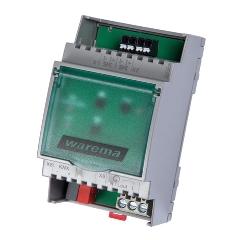
WAREMA KNX SA 2M230 REG User manual

WAREMA

WAREMA KNX SA 2M230 REG User manual

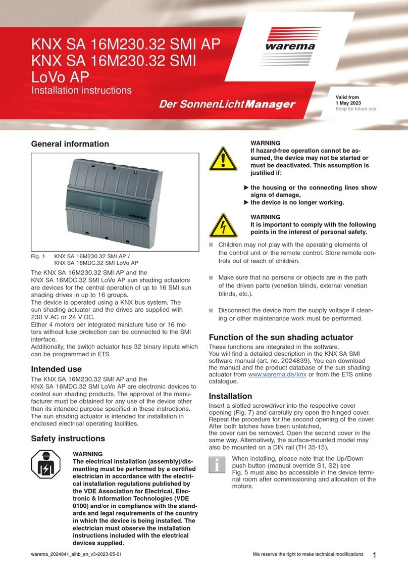
WAREMA KNX SA 16M230.32 SMI AP User manual

WAREMA

WAREMA KNX SA 16M230.32 SMI AP User manual

WAREMA BACnet 4M230.8I AP User manual

WAREMA

WAREMA BACnet 4M230.8I AP User manual

WAREMA KNX secure Series User manual

WAREMA

WAREMA KNX secure Series User manual

WAREMA WMS SA 1 UP User manual

WAREMA

WAREMA WMS SA 1 UP User manual

WAREMA KNX MSE 6M230 Series User manual

WAREMA

WAREMA KNX MSE 6M230 Series User manual

WAREMA 1MPF.4 UP User manual

WAREMA

WAREMA 1MPF.4 UP User manual

WAREMA KNX SA 16M230.32 SMI AP User manual

WAREMA

WAREMA KNX SA 16M230.32 SMI AP User manual

WAREMA LONMSE 2M230 Manual

WAREMA

WAREMA LONMSE 2M230 Manual

WAREMA KNX secure Series User manual

WAREMA

WAREMA KNX secure Series User manual

WAREMA LONMSE 2M230I Manual

WAREMA

WAREMA LONMSE 2M230I Manual

WAREMA KNX SA Series User manual

WAREMA

WAREMA KNX SA Series User manual

WAREMA Omnexo 1M230 UP User manual

WAREMA

WAREMA Omnexo 1M230 UP User manual

WAREMA KNX SA 16M230 SMI REG User manual

WAREMA

WAREMA KNX SA 16M230 SMI REG User manual

WAREMA LONMSE 6M230 User manual

WAREMA

WAREMA LONMSE 6M230 User manual

WAREMA Omnexo 2M230 AP User manual

WAREMA

WAREMA Omnexo 2M230 AP User manual

WAREMA 4M230.12 2Down REG User manual

WAREMA

WAREMA 4M230.12 2Down REG User manual

WAREMA Omnexo 2M230 REG User manual

WAREMA

WAREMA Omnexo 2M230 REG User manual

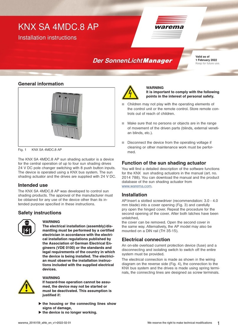
WAREMA KNX SA 4MDC.8 AP User manual

WAREMA

WAREMA KNX SA 4MDC.8 AP User manual

WAREMA KNX SA 4MDC REG User manual

WAREMA

WAREMA KNX SA 4MDC REG User manual

WAREMA KNX SA 4MDC.8 AP User manual

WAREMA

WAREMA KNX SA 4MDC.8 AP User manual

WAREMA KNX 2024236 User manual

WAREMA

WAREMA KNX 2024236 User manual

WAREMA KNX SA 2M230 REG User manual

WAREMA

WAREMA KNX SA 2M230 REG User manual

WAREMA KNX SA 2M230 AP Series User manual

WAREMA

WAREMA KNX SA 2M230 AP Series User manual

Popular Controllers manuals by other brands

Nelson ez pro instruction manual

Nelson

Nelson ez pro instruction manual

Siemens OpenAir GEB 131.1E quick start guide

Siemens

Siemens OpenAir GEB 131.1E quick start guide

Azbil BC-R25 Series user manual

Azbil

Azbil BC-R25 Series user manual

ascon TLK72 B operating instructions

ascon

ascon TLK72 B operating instructions

Forcepoint C1015 Hardware guide

Forcepoint

Forcepoint C1015 Hardware guide

Adtech ADTECH9 Series Programming manual

Adtech

Adtech ADTECH9 Series Programming manual

GE SX Series Installation and operation manual

GE

GE SX Series Installation and operation manual

Venmar 40455 Installation and owner's guide

Venmar

Venmar 40455 Installation and owner's guide

CARLO GAVAZZI RSBT Series troubleshooting guide

CARLO GAVAZZI

CARLO GAVAZZI RSBT Series troubleshooting guide

MarineKinetix MK4+ user manual

MarineKinetix

MarineKinetix MK4+ user manual

Skov DOL 834 Technical manual

Skov

Skov DOL 834 Technical manual

Carel IR32M manual

Carel

Carel IR32M manual

Siemens Flowrite 599 Series installation instructions

Siemens

Siemens Flowrite 599 Series installation instructions

Logitech G FLIGHT THROTTLE QUADRANT user guide

Logitech G

Logitech G FLIGHT THROTTLE QUADRANT user guide

Spa Power SP500A Mk2 user guide

Spa Power

Spa Power SP500A Mk2 user guide

Savant Director Lite HST-DIRECTORLITE Quick reference guide

Savant

Savant Director Lite HST-DIRECTORLITE Quick reference guide

Pride Controller GC2 Operation instructions

Pride

Pride Controller GC2 Operation instructions

AQUAESTIL FDS062 Series user manual

AQUAESTIL

AQUAESTIL FDS062 Series user manual

manuals.online logo
manuals.online logoBrands
  • About & Mission
  • Contact us
  • Privacy Policy
  • Terms and Conditions

Copyright 2025 Manuals.Online. All Rights Reserved.