manuals.online logo
Brands
  1. Home
  2. •
  3. Brands
  4. •
  5. SMC Networks
  6. •
  7. Accessories
  8. •
  9. SMC Networks PSE530 Series Instruction Manual

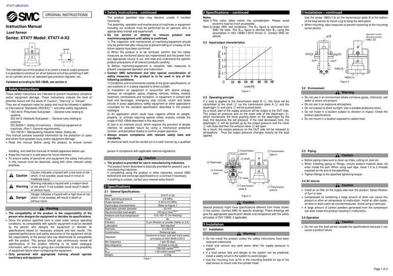
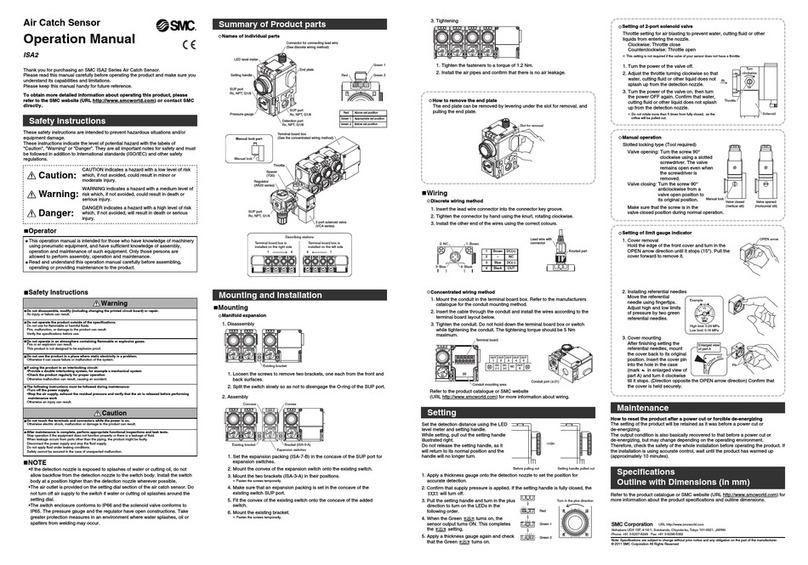
SMC Networks PSE530 Series Instruction Manual

Installation & Maintenance Manual
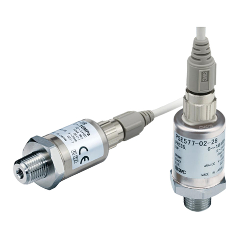
Compact Pressure Sensor
Series PSE530
NOTE
Follow the instructions given below when handling the
pressure sensor. Otherwise, the sensor may be damaged or
may fail, thereby resulting in malfunction.
•Do not drop, bring into collision with other objects or apply excessive
shock to the unit (980m/s2or more).
•Do not pull the lead wire with force or lift the main unit by holding the
lead wire. (Pulling strength less than 23N)
•Do not insert wire or other articles into the pressure port.
•Connect wires and cables correctly.
•Do not perform wiring while power is on.
•Do not wire with power cable or high-voltage cable in the same wire
route.
•Connect Terminal FG to ground when using a switching regulator
obtained on the commercial market.
•Install the air tube correctly in a safe area away from water and dust.
Indicates a potentially hazardous situation that
could result in death or serious injury if you do
not follow instructions.
Read this manual and follow its instructions. Signal words such as
WARNING and NOTE will be followed by important safety
information that must be carefully reviewed.
Gives you helpful information.
IMPORTANT MESSAGES
The Pressure Sensor and this manual contain essential information for
the protection of users and others from possible injury and property
damage and to ensure correct handling.
Please check that you fully understand the definition of the following
messages (signs) before going on to read the text, and always follow the
instructions.
Do not disassemble, modify (including change of printed
circuit board) or repair.
An injury or failure can result.
Do not operate outside of the specification range.
Fire, malfunction or sensor damage can result.
Please use after confirming the specification.
Do not operate in atmosphere of an inflammable, explosive
or corrosive gas.
Fire, an explosion and corrosion can result.
This pressure sensor is not an explosion proof type.
Model Indication Method
PSE53 0 M5
Nil
L
C2L
Option
Without cable
0
1
2
3
Pressure sensing range
High pressure[0 to 1MPa]
Vacuum [0 to -101kPa]
Low pressure [0 to 101kPa]
Compound pressure [-101 to 101kPa]
M5
R06
R07
Pipe Specification
M5 0.8
6 reducer
1/4inch reducer
Sensor cable (3m), ZS-26-F
Connector for sensor controller (1pc)
+Sensor cable (3m), ZS-26-J
Note) At the factory, the connector (ZS-28-C) is not connected
to the cable, but packed together with it for shipment.
3.4
5.4
5 5.5
4
3
29.4
27.2
M5 0.8
Pressure port
7.2
12
12
2.5
13
PSE53 -M5
5.4
3.4 Pressure port
7.2
12
D
45.5
43.3
PSE53 - R06
R07
Applicable port size(D)
6mm
1/4inch
Model No.
PSE53 -R06
PSE53 -R07
With sensor cable fitted
9.8
2.7
10.4
Outline with Dimensions
(
in mm
)
Installation
Model No.
Rated Pressure Range
Withstand Pressure
Fluid
Power Supply
Current Consumption
Repeatability
Power Supply Effect
Temperature Characteristic
Standard
Cable
PSE530-
0 to 1MPa
1.5MPa
Air, Non-corrosive gases, Non-flammable gases
12 to 24VDC, ripple(p-p)10% or less (Protection against inverse connection)
15mA or less
Voltage: 1 to 5V 2%F.S. or less (Rated pressure range)
Linearity : 1%F.S. or less Output impedance : Approx.1k
1%F.S. or less
1%F.S. or less based on analog output at 18V in the range of 12 to 24VDC
2%F.S. or less (25 reference)
IP40 (IEC 60529)
Operation : 0 to 50 ,Storage :-10 to 70 (No condensation, No freezing)
1000VAC, 50/60Hz, 1minute (Between wires and case)
5M or more 500VDC (Between wires and case)
10 to 500Hz 1.5mm or 98m/s
2
acceleration, 2 hours each direction
of X, Y and Z
980m/s23times each in directions of X ,Y and Z respectively
CE MARKING
Halogen free heavy insulation cable, 2.7, 0.15mm
2
, 3wire, 3m
500kPa
PSE531-
0 to -101kPa
PSE532-
0 to 101kPa
PSE533-
-101 to 101kPa
Analog
Output
Voltage
Output
Enclosure
Ambient Temperature
Withstand Voltage
Insulation Resistance
Vibration Proof
Impact Proof
Environment
Model No.
Port Size
Material Specification
Material
M5
M5 0.8
Body : SUS303
41g
7g
Body : PBT
38g
3.8g
Pressure sensor : Silicon O-ring : NBR
R06
6 Reducer
R07
1/4inch Reducer
Weight With cable(3m)
Excluding cable
Specification
1
Pressure or Vacuum
Analog output [ V ]
5
1 to 5VDC
AB
Model No.
Rated pressure
range
A
B
PSE530-
0 to 1MPa
0kPa
1MPa
PSE531-
0 to -101kPa
0kPa
-101kPa
PSE532-
0 to 101kPa
0kPa
101kPa
PSE533-
-101 to 101kPa
-101kPa
101kPa
Analog output
Observe the specified tightening torque when connecting pipes.
Refer to the following table for the appropriate torque values.
When connecting pipeline to the
sensor, apply a spanner vertically
to the piping section of the sensor.
Install the air piping correctly in a
safe area away from water and
dust.
Nominal size of Thread Tightening torque N • m
M5 1/6 rotations after tightening by hand
Hold the sensor and insert it into the
one-touch fitting carefully and securely
all the way to the bottom.
PSE##-TFI52GB
Safety Instructions
EMC Directive 89/336/EEC
EN61000-6-2:2001 Electromagnetic Compatibility (EMC). Generic
standards - lmmunity for industrial environments.
EN55011+A1:1998 Limits and methods of measurement of radio
disturbance characteristics of industrial, scientific
and medical radio-frequency equipment and light
industrial environments.
Output Specification
Internal Circuit and Wiring
Voltage output :
1 to 5V
Output impedance :
Approx. 1k
(Analog output)
Main circuit
12 to 24V
DC
+
-
1. Brown DC
(
+
)
4. Black OUT
3. Blue DC
(
-
)
How to connect the sensor cable (Optional)
Hold the female connector on the sensor cable.
Insert into sensor paying attention to the male connector direction.
Sensor
Male connector
Female connector
The sensor cable has a connector cover in order to prevent
removal of the female connector. Paying attention to the connector
cover direction, install on the sensor, rotate clockwise, and lock it.
To remove cable for sensor, rotate the connector cover anti-
clockwise, release the lock, and remove connector cover.
After removing connector cover, hold the female connector with
fingers and pull out.
Unlock
Lock
Sensor
Connector cover
To enquire about the product, please contact the following:
URLhttp://www.smcworld.com
Phone
AUSTRIA / (43) 2262-62 280 ITALY / (39) 02-92711
BELGIUM / (32) 3-355 1464 NETHERLANDS / (31) 20-531 8888
CZECH REP. / (420) 5-414 24611 NORWAY / (47) 67 12 90 20
DENMARK / (45) 70 25 29 00 POLAND / (48) 22-548 50 85
FINLAND / (358) 9-859 580 PORTUGAL / (351) 2 610 89 22
FRANCE / (33) 1-64 76 1000 SPAIN / (34) 945-18 4100
GERMANY / (49) 6103 4020 SWEDEN / (46) 8-603 0700
GREECE / (30) 1- 342 6076 SWITZERLAND / (41) 52-396 3131
HUNGARY / (36) 1-371 1343 TURKEY / (90) 212 221 1512
IRELAND / (353) 1-403 9000 UNITED KINGDOM / (44) 1908-56 3888
Connector Connecting/Disconnecting
•When connecting the connector, insert it straight onto the pins
holding the lever and connector body, and lock the connector
by pushing the lever claw into the square groove in the housing
until connector clicks.
•When disconnecting the connector, press the connector lever
to disengage the lever claw from the square groove. Then pull
the connector straight out.
PSE200 Series PSE300 Series
Connector for Sensor
Lead Wire
Lever
Lever
Attaching the connector to the lead wire
•Strip the sensor wire as shown in the right figure.
•The core of the corresponding
color shown in the following table is
put into the pin of the number printed
on the e-con connector and pushed
to the back.
•Check that the above-mentioned
preparation work has been performed
correctly, then Part A shown in the figure is pushed in by hand
to make temporary connection.
•Part A center is pressed straight in using a tool, such as pliers.
•Re-use cannot be performed once the e-con connector has
been completely crimped.
•In case of connection failure such as incorrect order of wires or
incomplete insertion, please use a new e-con connector.
•When connecting to PSE200/PSE300 controllers, please use
the connector for sensor (ZS-28-C)
or as detailed below.
•Please contact connector manufacturer about catalogue.
Color of Insulation
Brown (DC + )
N.C.
Blue (DC - )
Black (IN:1 to 5VDC)
Pin No.
1
2
3
4
Manufacturer
(c)Sumitomo 3M
Tyco Electronics AMP
OMRON
Model No.
37104-3101-000FL
3-1473562-4
XN2A-1430
Insulation
Connector
cover 20mm or more
A
Installation (continue)
PSE##-TFI52GB

This manual suits for next models

3

Other SMC Networks Accessories manuals

SMC Networks XT477 User manual

SMC Networks

SMC Networks XT477 User manual

SMC Networks SMCMT01-Z Operator's manual

SMC Networks

SMC Networks SMCMT01-Z Operator's manual

SMC Networks IZD10-*10 Series User manual

SMC Networks

SMC Networks IZD10-*10 Series User manual

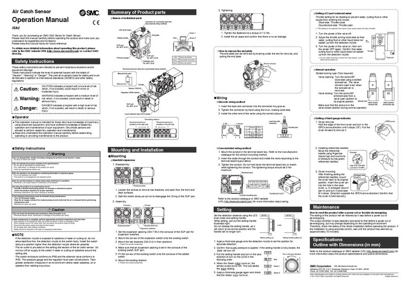
SMC Networks ISA2 Installation manual

SMC Networks

SMC Networks ISA2 Installation manual

SMC Networks PSE510 Series User manual

SMC Networks

SMC Networks PSE510 Series User manual

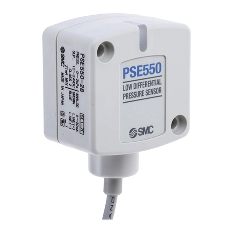
SMC Networks PSE550 User manual

SMC Networks

SMC Networks PSE550 User manual

SMC Networks PSE575 Instruction Manual

SMC Networks

SMC Networks PSE575 Instruction Manual

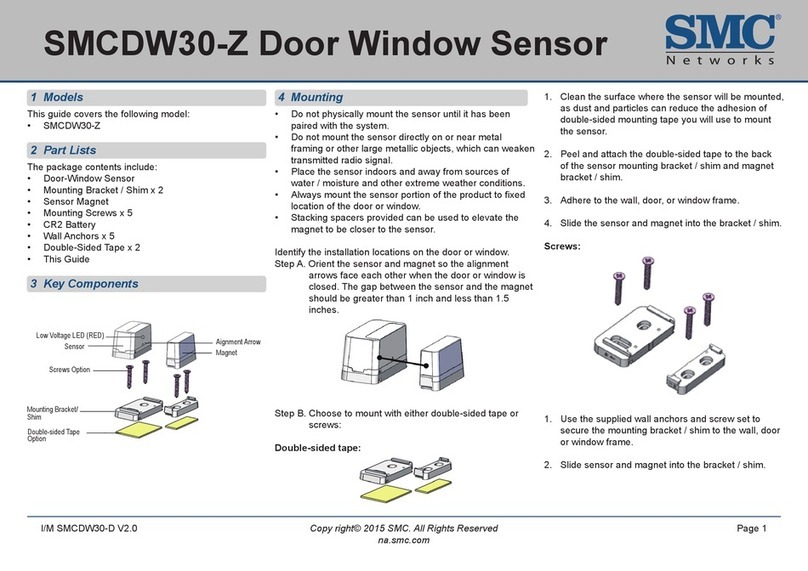
SMC Networks SMCDW30-Z User manual

SMC Networks

SMC Networks SMCDW30-Z User manual

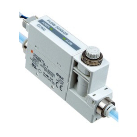
SMC Networks PFMV5 Series User manual

SMC Networks

SMC Networks PFMV5 Series User manual

SMC Networks HRG001-W User manual

SMC Networks

SMC Networks HRG001-W User manual

SMC Networks ISA2 Series Installation manual

SMC Networks

SMC Networks ISA2 Series Installation manual

SMC Networks PSE550 User manual

SMC Networks

SMC Networks PSE550 User manual

SMC Networks PFM5 Series Instruction Manual

SMC Networks

SMC Networks PFM5 Series Instruction Manual

SMC Networks PSE570 User manual

SMC Networks

SMC Networks PSE570 User manual

SMC Networks PSE57 Series User manual

SMC Networks

SMC Networks PSE57 Series User manual

SMC Networks D-MP Series User manual

SMC Networks

SMC Networks D-MP Series User manual

SMC Networks D-MP Series User manual

SMC Networks

SMC Networks D-MP Series User manual

SMC Networks SMC-520 User manual

SMC Networks

SMC Networks SMC-520 User manual

SMC Networks XT477-4-X2 User manual

SMC Networks

SMC Networks XT477-4-X2 User manual

SMC Networks PSE200 Series User manual

SMC Networks

SMC Networks PSE200 Series User manual

SMC Networks PFM5 Series User manual

SMC Networks

SMC Networks PFM5 Series User manual

SMC Networks PFM5 Series User manual

SMC Networks

SMC Networks PFM5 Series User manual

SMC Networks ADVANCE TECH HX User manual

SMC Networks

SMC Networks ADVANCE TECH HX User manual

SMC Networks IMU-007 User manual

SMC Networks

SMC Networks IMU-007 User manual

Popular Accessories manuals by other brands

STEINEL IS D360-120 installation instructions

STEINEL

STEINEL IS D360-120 installation instructions

Honeywell NOTIFIER FSV-951 Installation and maintenance instructions

Honeywell

Honeywell NOTIFIER FSV-951 Installation and maintenance instructions

ADT 967 Manual supplement

ADT

ADT 967 Manual supplement

Omron E3ZM - datasheet

Omron

Omron E3ZM - datasheet

Pilz PSEN cs6.1n Operator's manual

Pilz

Pilz PSEN cs6.1n Operator's manual

Pass S02TG manual

Pass

Pass S02TG manual

Shelly UNI User and safety guidelines

Shelly

Shelly UNI User and safety guidelines

Sony ICX274AL manual

Sony

Sony ICX274AL manual

Omron E3S-LS10XE4 2M manual

Omron

Omron E3S-LS10XE4 2M manual

Medisana 60226 instruction manual

Medisana

Medisana 60226 instruction manual

Ningbo SK-5801 User guider

Ningbo

Ningbo SK-5801 User guider

Duramaxx 10027670 manual

Duramaxx

Duramaxx 10027670 manual

INNOBIZ Audelia Instructions for use

INNOBIZ

INNOBIZ Audelia Instructions for use

LI-COR 1400-101 Operation and installation instructions

LI-COR

LI-COR 1400-101 Operation and installation instructions

schmersal BNS 33 series operating instructions

schmersal

schmersal BNS 33 series operating instructions

Ambient Weather PM2.5 user manual

Ambient Weather

Ambient Weather PM2.5 user manual

PCB Piezotronics 4106-01A Installation and operating manual

PCB Piezotronics

PCB Piezotronics 4106-01A Installation and operating manual

Reer ADMIRAL AD Quick installation guide

Reer

Reer ADMIRAL AD Quick installation guide

manuals.online logo
manuals.online logoBrands
  • About & Mission
  • Contact us
  • Privacy Policy
  • Terms and Conditions

Copyright 2025 Manuals.Online. All Rights Reserved.