INSTALLATION
Ensure the power has been turned OFF at the circuit
breaker.
Prepare the wires with proper length (cut the excessive
length, if necessary) and strip for connection. Connect
the sensor wires to the wires of line voltage and load
according to the above wiring diagram of desired control.
Carefully bend the wires in the wall box after all wires are
properly connected. Mount the sensor in the wall box with
the screws provided.
Conduct sensor operation test (refer to the TESTING
section). Replace the wall plate cover after sensor testing
and setting completed.
1.
2.
3.
4.
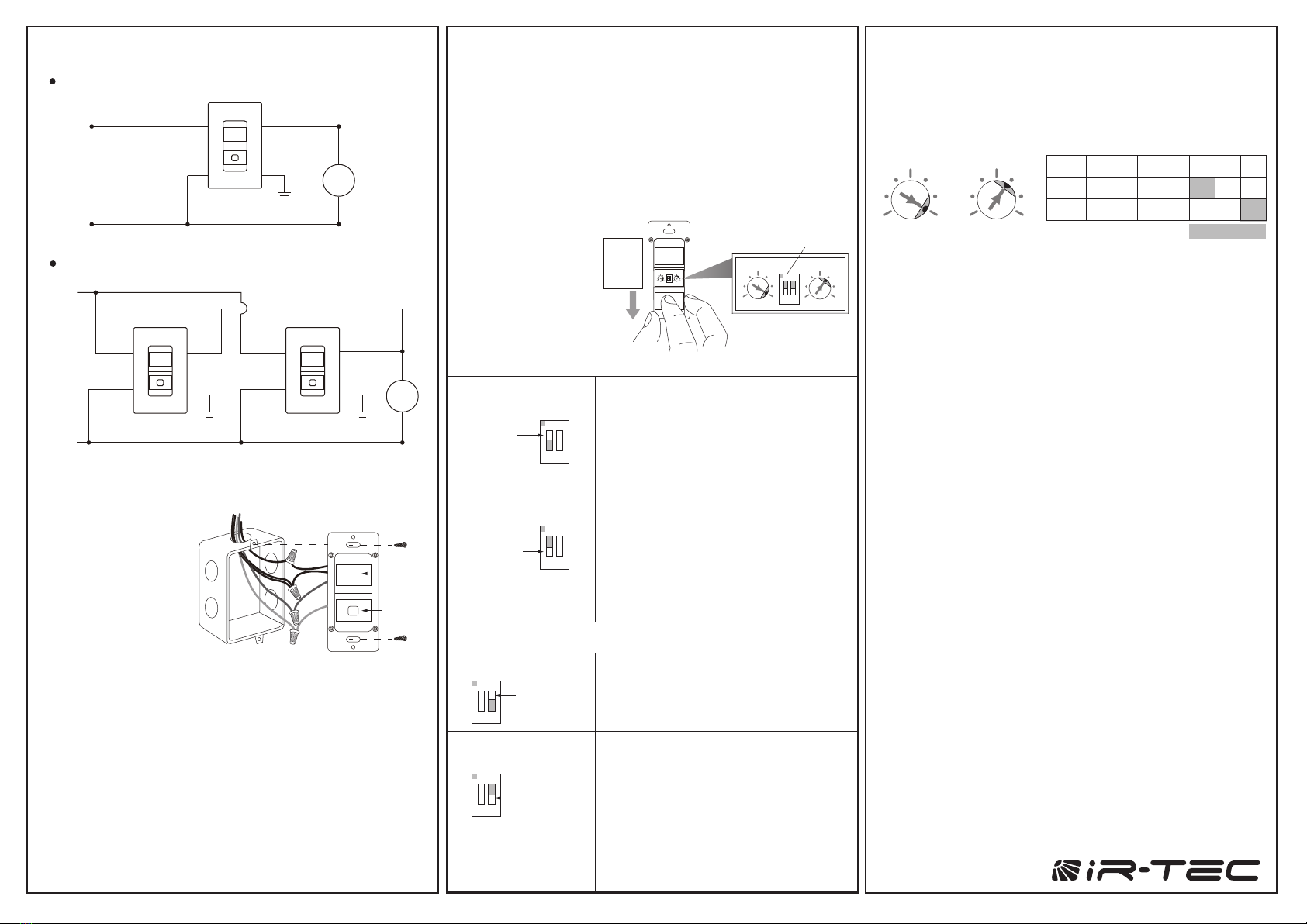
WIRING DIAGRAM
Sensor
Red
Black
Black
Hot(Black)
Line
120VAC, 60Hz
Green
Ground
Load
White
White
Neutral(White)
SensorSensor
RedRed
Black
BlackBlack
Hot
(Black)
Line
120VAC, 60Hz
LoadWhite
WhiteNeutral
(White)
Green
Ground
Green
Ground
White
The sensor may be available with other control options,
assistance.
NOTE: Connect the
GREEN wire to the
GROUND for safety.
LENS
PUSH-
BUTTON
IR-TEC International Ltd. warranties this product to be free of defects
in materials or workmanship for a period of five years from date
of shipment. There are no obligations or liabilities on the part of
IR-TEC International Ltd. for consequential damages arising out or in
connection with the use or performance of this product or other indirect
damages with respect to loss of property, revenue, or profit, or cost of
removal, installation or reinstallation.
WARRANTY
Sensor Mode
Push-button Control
Occupancy Sensor
(Auto-ON, Auto-OFF)
Occupancy sensor switches the light ON
automatically when it detects the presence
of an occupant. The sensor will switch
the light OFF automatically if no occupant
activity has been detected before the time
delay elapses.
ON
1 2
Vacancy Sensor
(Manual-ON, Auto-OFF)
Vacancy sensor requires the user to
manually press the push-button to turn ON
the light. The sensor will switch the light
OFF automatically if no occupant activity
has been detected before the time delay
elapses.
NOTE - The sensor will automatically turn
ON the light if it detects occupant activity
within 30 seconds after time delay elapsed.
Presentation Mode
Pressing the push-button during occupied
state will turn OFF the load immediately and
hold off until the push-button is pressed
again.
In Presentation Mode (PM), pressing
the push-button will turn OFF the lights
immediately, and the lights will remain off
even if motion is detected. Pressing the
push-button again will turn the light ON and
the sensor will operate per its settings. If the
time delay expires and no occupant activity
has been detected, the sensor will return to
its normal operation. The lights will turn on
with the next motion detected.
SW1=ON
Manual ON/OFF
ON
1 2
SW1=OFF
ON
1 2
SW2=ON
ON
1 2
SW2=OFF
OPERATION
The LBS-701 series wall switch sensor employs passive
infrared (PIR) sensing technology to monitor the occupancy
status within its coverage, and control the connected load as
per sensor setting. The sensor can be programmed to control
the load as an Occupancy Sensor or Vacancy Sensor via
setting DIP switch #1. The push-button operation can be
programmed to turn the load ON and OFF manually or in
Presentation Mode (PM) for specific requirement via setting
DIP switch #2.
This is the delay time that the LBS-701 series sensor will hold
the load on after the last motion detected. The factory setting is
10 minutes, and it can be changed by pointing the arrowhead
of potentiometer to the specific position.
TIME - Delay time
This is the threshold of ambient light level that the LBS-701S
sensor will inhibit switching on the load. The factory setting is
ALS disabled (24 Hr) for ease of testing, and it can be changed
by pointing the arrowhead of potentiometer to the specific
position.
LUX – Ambient light level (LBS-701S only)
TESTING
Restore line voltage power for the sensor at circuit breaker.
An LED behind the sensor lens will blink to indicate the
motion sensed.
Replace the wall plate cover after completing sensor testing
and setting.
1.
2.
3.
NOTE: The connected load will be switched on as delay time
set (factory default 10 minutes) once apply the power. The delay
time can be set to the shortest (10 seconds) for ease of testing.
Ensure to set the TIME as desired for optimum operation
after testing.
LUX
1 7
2 6
3 5
4
TIME
1 7
2 6
3 5
4
LUX
TIME T
POS. 1 2 3 4 5 6 7
1’ 3’ 5’ 10’ 20’ 30’
5 10 30 50
100 150 24H
Factory Set
To change the sensor
operation mode or
settings, press the
push-button cover
and slide it down as
shown.
The LBS-701S features ambient light sensor to inhibit
unnecessary lighting when ambient light is higher than the
level set. The time delay (TIME) and ambient light level (LUX)
settings can be changed by rotating the respective Accu-Set
potentiometer at different positions.
SETTING
3-Way Control
Single-Pole Control
Slide ON
1 2
LUX TIME
Press
&
ON
1 2
LUX TIME
DIP
Switch


