SMC Networks LOOPANTNVIS3 User manual


Issue 1
1
Preface
SMC - South Midlands Communications Ltd was established in 1958 and
initially specialized in antenna support masts, towers and HF antennas. SMC is
now recognized globally as a specialist communications company.
Over the last 50 years the SMC product range has grown to include pneumatic
telescopic masts, aluminum lattice masts, high-level photography solutions, Mil’
specification antenna positioners and two way radio products including GPS,
AVLS and data transfer.
SMC are able to advise, design, supply and install mobile communications
systems, from the simple to more complex and integrated networks.
Although every care is taken in the production of this publication it may contain
technical inaccuracies or typographical errors. SMC may make improvements
and or changes in the product detailed in this manual at any time without notice.
Correspondence regarding this publication should be addressed to:
South Midlands Communications Ltd
SM House, School Close
Chandlers Ford Industrial Estate
Eastleigh, Hampshire
SO53 4BY
United Kingdom
Tel: +44 (0)23 8024 6200
Fax: +44 (0)23 8024 6206
Email: sales@smc-comms.com
Web: www.smc-comms.com

Issue 1
2
Safety Information
Always follow the Operating Instructions
Installation must only be carried out by authorized
personnel
The Folding Loop Antenna is heavy and care should be
taken when installing the unit.
Beware of overhead obstructions and power lines. Drive the
vehicle accordingly.
Do not operate the Folding Loop Antenna Outside of the
operating temperature range -35
º
C to +70
º
C
.
Take care not to trap fingers whilst raising and lowering
the Folding Loop Antenna. Always wear protective
gloves.
Ensure that the Folding Loop Antenna is securely mounted
to the vehicle
Do not use the antenna unless it is positioned correctly in
the Operational Position
Do not attempt to apply RF power if the Folding Loop
Antenna is not powered with the correct DC supply
Do not touch the Folding Loop Antenna when in use and
RF power is applied.
Failure to observe any of the warnings in this manual may result in
personal injury, death, or equipment damage. South Midlands
Communications Ltd (SMC) accepts no responsibility for
unauthorized use.

Issue 1
3
Product Introduction
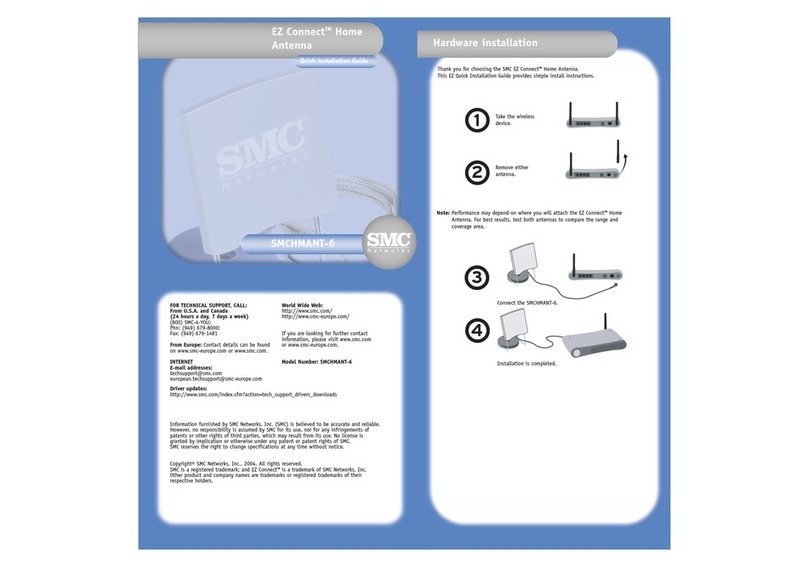
The Folding Loop Antenna has been designed and manufactured to meet the
requirements of NVIS HF mobile communications for both on-road and off-road
vehicles.
High conductivity tubing is used in the loop element to provide high
communication efficiency, and a custom-modified electronic tuner is used to
provide a 50-ohm nominal termination impedance at all operating frequencies.
The termination arrangement is hermetically sealed to IP66 specifications.
Following initialisation, where the tuner unit memorises each operating frequency
used by the HF transceiver, each subsequent tune operation is completed within
10 mS. This is achieved by the tuner having on-board memory to instantaneously
measure and determine the operating frequency of each operating channel, and
to switch in the required matching configuration for each stored channel. The
Folding Loop Antenna is inherently compatible with virtually any HF transceiver
over the operational frequency range and power rating with no separate channel
control required for the antenna.
The radiation pattern presented by the Folding Loop Antenna is shown above
in 3D, giving maximum radiation in an arc from the front of the vehicle, over the
vehicle (thus giving excellent NVIS performance), and to the rear of the vehicle.
The front and rear radiation paths also provide excellent results for ground-wave
communication between a fleet of vehicles travelling in line. This assumes the
loop is mounted with the element in the same plane as the line of the vehicle (i.e.
from front to rear) and with the Folding Loop Antenna in the Operational
Position.

Issue 1
4
Specification
Dimensions
Weight:
14.5 kg
Frequency Range:
3.0 –15.0 MHz
TX Power Input Range:
1.5-200 Watts PEP
Continuous TX CW/Data Power:
80W
Number of operating channels:
Unlimited
Non-Volatile Channel Memory
Addresses:
170 (165 TX, 5 RX)
Input Impedance Range
45-55 ohms
VSWR
Typically less than 2:1 when tuned, (3:1 max)
DC Operating Range
+10.5V to 18.0V DC,
(+13.8V DC nominal)
DC Current:
230 mA average
Initial tuning response time:
(For initial memory setting only)
Up to 20 seconds max
Recurrent tuning response time:
(for on-air use inc. freq hopping)
Typically less than 10 ms per channel
Operational Temperature
-35° to +70°C
Control cable
Standard 50-ohm coaxial cable plus 13.8V
nominal DC feed
957mm
1660mm
800mm
225mm

Issue 1
5
Retainer Upstand
Antenna
Features
Catch
Base
Electrical
Enclosure
Locking Arm
Base
Roof Rack
Plate
Locking Knob
Locking Knob

Issue 1
6
Installation
The following procedure describes how to install the Folding Loop Antenna on
to a pair of vehicle roof bars.
The Folding Loop Antenna is heavy and care should be
taken when installing the unit.
Take care not to trap fingers when installing the Folding Loop
Antenna. Always wear protective gloves when raising or
lowering the Folding Loop Antenna.
1. Remove the Folding Loop Antenna from its packaging and place next to
the vehicle.
2. Adjust the roof bars on the vehicle so that they are 800mm apart between
the centre of each bar. Ensuring the roof bars are parallel to each other.
3. Lock the Folding Loop Antenna into the Operational Position. Ensuring
that the locking Screw on both Locking Arms is engaged into its
corresponding Catch on it’s the Base.
4. Place the Folding Loop Antenna onto the roof bars, with the angle
section of the loop facing to the front of the vehicle, and support.
5. Place the a Roof Rack Plates under the vehicle roof bars as shown and
bolt into position using the supplied bolt, nut and washers. Repeat this
procedure for all six fixing positions on the two Bases.
Front of
Vehicle
Vehicle
Roof Bars
800mm

Issue 1
7
6. Place both Retainer Upstands onto the roof bars as shown.
7. Place the Roof Rack Plates under the vehicle roof bars and bolt the
Retainer Upstands into position so that they are secure but can be
adjusted.
8. Release the Folding Loop Antenna from it Operational Position, by
turning the Locking Knobs counter clockwise, disengaging the Locking
Arms from the Catch’s. Lower the Folding Loop Antenna down onto the
Retainer Upstands using the Locking Arms.
Take care not to drop the Folding Loop Antenna on the
Retainer Upstands.
455mm
680mm

Issue 1
8
9. Adjust the Retainer Upstands so that they allow the Locking Knobs to
engage into them.
10.Secure the Locking Knob in position and tighten the bolts securing the
Retainer Upstands to the roof bars.
Ensure the Folding Loop Antenna is securely mounted to the
vehicle and that all bolts are securely tightened.

Issue 1
9
Electrical
Antenna Connector
The RF Coaxial Cable should be connected between the Antenna Socket on
the Folding Loop Antenna and the transceiver antenna connector. As the
Antenna Connector is not 100% watertight, after fitment use the supplied self-
amalgamating rubber tape to seal the connection. Proceed as follows:
1. Connect RF Coaxial Cable Connector to the Antenna Socket on the
Enclosure
2. Cut the self-amalgamating tape to the desired length
3. Remove the plastic backing from the self-amalgamating tape
4. Stretch the tape to 2-3 times its initial length while wrapping this around
the assembled RF Coaxial Cable Connector and Antenna Socket until a
complete weatherproof seal is made.
DC Connector
The shielded 13.8V DC Cable should be connected to a 13.8V nominal DC
source, which as a minimum is present whenever the transceiver is switched on.
The red inner is 13.8V DC Positive (+), the black (or depending on version, blue)
inner is 13.8V DC Negative (-). It is not necessary to connect the DC cable
shield, however this may be connected to the vehicle chassis to provide a better
RF ground if required. Proceed as follows:
1. Connect the DC Lead Plug to the DC Socket on the Enclosure
2. Connect a 13.8V nominal DC source
+ DC Positive RED OR BROWN
- DC Negative BLACK OR BLUE
NOTE: CABLE COLOUR CODING
Following the harmonisation of cable colour codes within the E.U. the DC Power
cable may be coded as below:
BROWN = + DC Positive (Originally coded RED)
BLUE = - DC Negative (Originally coded BLACK)
The RF and DC cables may be shortened as required by the user. Specific cable
lengths can be supplied upon request.

Issue 1
10
Operation
The following section describes how to raise the Folding Loop Antenna into the
operational position, lower the antenna into the stored position and tuning the
antenna.
Take care not to trap fingers whilst raising the Folding Loop
Antenna. Always wear protective gloves when raising or
lowering the Folding Loop Antenna.
Take care as some surfaces may become hot or cold
depending on environmental conditions.
Do not to rotate the Folding Loop Antenna past 90°
Do not touch the Folding Loop Antenna when in use and RF
power is applied.
Raising the Folding Loop Antenna
1. Release the Locking Knobs holding the NVIS Loop Antenna in the
Stored Position, by turning them counter clockwise until they have fully
disengaged from the Retainer Upstands.

Issue 1
11
2. Lift up both Locking Arms and use them to rotate the Folding Loop
Antenna into the Operational Position.
3. Push each Locking Arm into the Catch on its corresponding Base.

Issue 1
12
4. Secure the Locking Knobs on each Locking Arm into the Catch by
turning them clockwise until they are fully engaged into the Catches.
Ensure the each Locking Knob is engaged into the Catch
on the Folding Loop Antenna Base.

Issue 1
13
Storing the Folding Loop Antenna
1. Release one of the Locking Knobs on the Locking Arm holding the
Folding Loop Antenna in the Operational Position by turning it counter
clockwise until it has fully disengaged from the Catch.
2. Rotate the Locking Arm away from the Catch
3. Release the other Locking Knob on the Locking Arm, rotate the
Locking Arm away from the Catch and gently lower the Folding Loop
Antenna using both Locking Arms.
Take care not to drop the Folding Loop Antenna on the
Retainer Upstands.
4. Once the Folding Loop Antenna is lower onto the Retainer Upstands,
turn the Locking Knobs clockwise and secure.
Tuning Method
Once the Installation of the Folding Loop Antenna is completed, it is
recommended that the tuner is initialised. To initialise the Tuner proceed as
follows:
1. Place the Folding Loop Antenna into the Operational Position
2. For each operational channel the transmitter should be placed in
continuous carrier transmit mode with a power output of 5-80W for a
period of 20-30 seconds per channel.
NOTE: The tuner will automatically memorise each frequency and
associated tuning point, subsequently the tuner will auto-tune to these
memorised transmit channels with in a few milliseconds.
For greater receiver efficiency in non-hopping modes, the antenna is factory-set
to automatically store its tuning settings for the last tuned transmit frequency. The
tuner can be factory-set to ‘un-tuned’ in receive mode, allowing wide-band
reception for frequency hopping modes.

Issue 1
14
Maintenance
Check the condition of the connectors and cables every 14 days. Replace
where necessary.
Check all fixings and hardware every 14 days. Ensure the Folding Loop
Antenna is securely mounted to the vehicle. Tighten fixings or Replace
where necessary.
Fuse Replacement
To replace the internal Fuse inside the Electrical Enclosure, proceed as
follows.
Isolate DC power and RF power to the Folding Loop
Antenna
1. Ensure DC Power and RF Power has been Isolate
2. Unscrew the 4 captive screws on the Enclosure Lid
3. Remove the Enclosure Lid
4. Remove the Fuse Cover
5. Remove the Fuse and replace
Current Rating 2A
Length 32mm
Diameter 6.3mm
6. Replace the Enclosure Lid and secure the screws

Issue 1
15
Notes

Issue 1
16
Table of contents
Other SMC Networks Antenna manuals

SMC Networks
SMC Networks HMANT-6 User manual
SMC Networks
SMC Networks HMANT-6 - FICHE TECHNIQUE Installation guide

SMC Networks
SMC Networks HMANT-4 - FICHE TECHNIQUE User manual

SMC Networks
SMC Networks HMANT-4 User manual

SMC Networks
SMC Networks SMCANT-OOM5P User manual
SMC Networks
SMC Networks SMCAMP-1000 User manual
Popular Antenna manuals by other brands

SmartBridges
SmartBridges sB3021 user guide

Directive Systems & Engineering
Directive Systems & Engineering DS 88-8 quick start guide

Strong
Strong SlimSat SA60 user manual

Intellian
Intellian v130G Installation and operation user guide

Starwin
Starwin V9 OTM45 Installation and user manual

Channel Master
Channel Master CM-1776 Assembly