manuals.online logo
Brands
  1. Home
  2. •
  3. Brands
  4. •
  5. SMC Networks
  6. •
  7. Controllers
  8. •
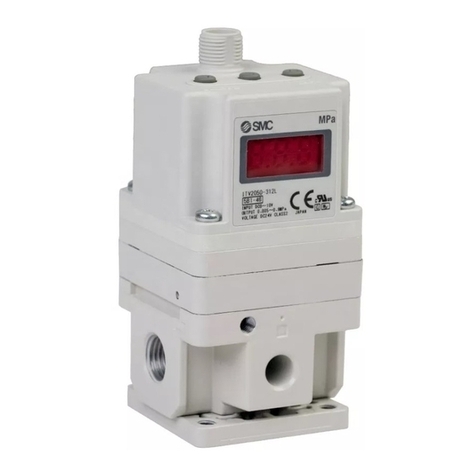
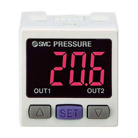
  9. SMC Networks PSE200-M Series User manual

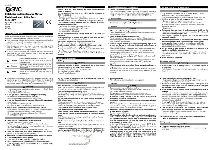
SMC Networks PSE200-M Series User manual

This manual suits for next models

5

Other SMC Networks Controllers manuals

SMC Networks C RB 10 Series User manual

SMC Networks

SMC Networks C RB 10 Series User manual

SMC Networks PSE303-LBC User manual

SMC Networks

SMC Networks PSE303-LBC User manual

SMC Networks MXQ6 Series User manual

SMC Networks

SMC Networks MXQ6 Series User manual

SMC Networks ITV1000 series User manual

SMC Networks

SMC Networks ITV1000 series User manual

SMC Networks ITV10*0-CC****-Q Series Manual

SMC Networks

SMC Networks ITV10*0-CC****-Q Series Manual

SMC Networks LEYG User manual

SMC Networks

SMC Networks LEYG User manual

SMC Networks LEG Series User manual

SMC Networks

SMC Networks LEG Series User manual

SMC Networks 55-JCM Series User manual

SMC Networks

SMC Networks 55-JCM Series User manual

SMC Networks ITV1000 series User manual

SMC Networks

SMC Networks ITV1000 series User manual

SMC Networks PSE300 Series User manual

SMC Networks

SMC Networks PSE300 Series User manual

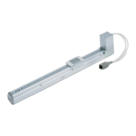
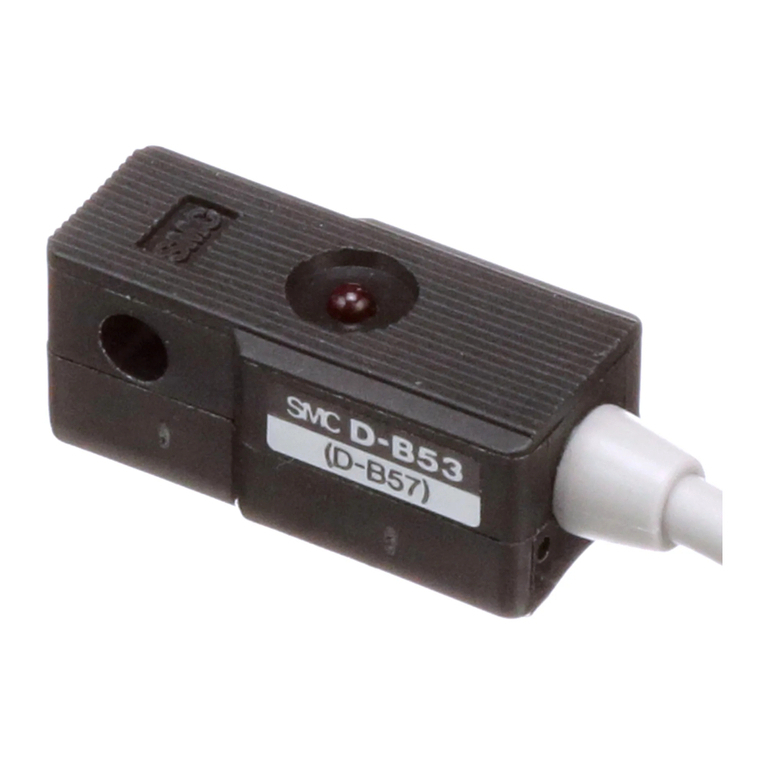
SMC Networks D-B53 Series User manual

SMC Networks

SMC Networks D-B53 Series User manual

SMC Networks LEL25M User manual

SMC Networks

SMC Networks LEL25M User manual

SMC Networks LEYG25M Manual

SMC Networks

SMC Networks LEYG25M Manual

SMC Networks LEJ Series User manual

SMC Networks

SMC Networks LEJ Series User manual

SMC Networks AR20 Series User manual

SMC Networks

SMC Networks AR20 Series User manual

SMC Networks ITV0000 Series User manual

SMC Networks

SMC Networks ITV0000 Series User manual

SMC Networks EX600-SPN1 Instruction Manual

SMC Networks

SMC Networks EX600-SPN1 Instruction Manual

SMC Networks LEJS Series User manual

SMC Networks

SMC Networks LEJS Series User manual

SMC Networks ASD F-A Series User manual

SMC Networks

SMC Networks ASD F-A Series User manual

SMC Networks LECSN-T Series User manual

SMC Networks

SMC Networks LECSN-T Series User manual

SMC Networks JXC73 Series Owner's manual

SMC Networks

SMC Networks JXC73 Series Owner's manual

SMC Networks JXC73 Series User manual

SMC Networks

SMC Networks JXC73 Series User manual

SMC Networks ClimateWorx FieldServer ProtoNode FPC-N34 User guide

SMC Networks

SMC Networks ClimateWorx FieldServer ProtoNode FPC-N34 User guide

SMC Networks LECPMJ Series User manual

SMC Networks

SMC Networks LECPMJ Series User manual

Popular Controllers manuals by other brands

Sunricher SR-ZV9003T3-RGBW-US Installation

Sunricher

Sunricher SR-ZV9003T3-RGBW-US Installation

Ksenia intro Installation and configuration manual

Ksenia

Ksenia intro Installation and configuration manual

Inovance CAN200 Series manual

Inovance

Inovance CAN200 Series manual

Gauzy LC6 FLEX Controller Installation and operation guide

Gauzy

Gauzy LC6 FLEX Controller Installation and operation guide

Viking SLP-1 Technical practice

Viking

Viking SLP-1 Technical practice

CKD KBX-30E-U Series instruction manual

CKD

CKD KBX-30E-U Series instruction manual

Sharp Energy Sun Flux User manual & installation guide

Sharp Energy

Sharp Energy Sun Flux User manual & installation guide

Yamaha RCX40 user manual

Yamaha

Yamaha RCX40 user manual

AB Quality PowerFlex 400 Frames D-H Service bulletin

AB Quality

AB Quality PowerFlex 400 Frames D-H Service bulletin

Yamaha MJC8 owner's manual

Yamaha

Yamaha MJC8 owner's manual

AL-KO ATC operating instructions

AL-KO

AL-KO ATC operating instructions

Savant SmartControl 2 Deployment guide

Savant

Savant SmartControl 2 Deployment guide

GameSir T3S user manual

GameSir

GameSir T3S user manual

Kostal inveor operating manual

Kostal

Kostal inveor operating manual

Emerson Yarway 20-55 Operating and safety instructions

Emerson

Emerson Yarway 20-55 Operating and safety instructions

CoCo ACM-LV24 Quick installation guide

CoCo

CoCo ACM-LV24 Quick installation guide

Brooks SLA5810/20 Installation and operation manual

Brooks

Brooks SLA5810/20 Installation and operation manual

SIGMA TEK SR 011 Technical manual

SIGMA TEK

SIGMA TEK SR 011 Technical manual

manuals.online logo
manuals.online logoBrands
  • About & Mission
  • Contact us
  • Privacy Policy
  • Terms and Conditions

Copyright 2025 Manuals.Online. All Rights Reserved.

Multi-channel Controller
Series PSE200
How to Order
PSE20 0
Nil
4C
Option 2
Without connector
0
1
Input/Output specifications
NPN 5 outputs + Auto shift input
PNP 5 outputs + Auto shift input
Nil
M
Unit specifications
With unit display switching function
Fixed SI unit Note)
Sensor connector (4 pcs.)
Nil
Option 1
Accessory: Power supply/Output connection cable (2 m)
Without panel mount/protective cover
Panel mount
Front protective cover + Panel mount
Panel mount adapter
Mounting screws (M3 x 8L)
(Accessory)
Panel
Connector
Waterproof seal
(Accessory)
Waterproof seal
(Accessory)
Panel mount adapter
48 conversion adapter
Mounting screws (M3 x 8L)
(Accessory)
Panel
Power supply/Output connection cable
ZS-26-A
Included with the controller.
Front protective cover
Option
When only optional parts are required, order with the part numbers listed below.
Description Part no.
ZS-26-B
ZS-26-01
ZS-26-C
Note
Waterproof seal, screws included
Panel mount adapter
Front protective cover
Front protective cover +
Panel mount adapter
48 conversion adapter
Connector
ZS-26-D
ZS-26-E (4 pcs. per set)
Order panel mount adapter separately.
A
B
M
Note) Fixed unit
For vacuum low pressure & compound
pressure: kPa
For high pressure: MPa
This adapter is used to
mount Series PSE200 on
the panel fitting of Series
PS100.
16-3-6
SHOP ONLINE at www.airlinehyd.com
800-999-7378
Specifications
Model PSE200
NPN open collector
PSE201
PNP open collector
Output specification
Power supply voltage
Current consumption
Power supply voltage for sensor
Power supply current for sensor Note 1)
Sensor input
Hysteresis
Switch output
Response time
Repeatability
Setting/Display accuracy
Display
Indication light
Auto shift input
Auto identification function Note 2)
Resistance
Temperature characteristics
Connection
Material
Weight
12 to 24 VDC ±10%, Ripple (p-p) 10% or less (With power supply polarity protection)
55 mA or less (Current consumption for sensor is not included.)
[Power supply voltage] –1.5 V
40 mA maximum (100 mA maximum for the total power supply current when 4 sensors are input.)
1 to 5 VDC (Input impedance: Approx. 800 kΩ)
4 inputs
With excess voltage protection (Up to 26.4 V)
Variable
3-digit fixed
5 outputs (CH1: 2 outputs, CH2 to 4: 1 output)
80 mA
30 VDC (With NPN)
1 V or less (With load current of 80 mA)
With short circuit protection
5 ms or less
With anti-chattering function, Response time selection: 20 ms, 160 ms, 640 ms
±0.1% F.S. or less
±0.5% F.S. ±1 digit or less (at ambient temperature of 25°±3°C)
For measured value display: 4-digit, 7-segment indicator, Display color: Yellow
For channel display: 1-digit, 7-segment indicator, Display color: Red
Red (Lights up when output is ON.)
Non-voltage input (Reed or Solid state), Input 10 ms or more, Independently controllable auto shift function ON/OFF
With auto identification function
Front face: IP65, Other: IP40
Operating: 0°to 50°C, Stored: –10°to 60°C (No freezing or condensation)
Operating/Stored: 35 to 85% RH (No condensation)
10 to 500 Hz at whichever is smaller of 1.5 mm amplitude or 98 m/s2acceleration, in X, Y, Z directions for 2 hrs. each (De-energized)
980 m/s
2
in X, Y, Z directions, 3 times each (De-energized)
±0.5% F.S. or less based on 25°C
Power supply/Output connection: 8P connector, Sensor connection: 4P connector
Enclosure: PBT; Display: Transparent nylon; Back rubber cover: CR
Approx. 60 g (Power supply/output connecting cable not included)
No. of inputs
Input protection
Hysteresis mode
Window comparator mode
No. of outputs
Maximum load current
Maximum load voltage
Residual voltage
Output protection
Anti-chattering function
Enclosure
Ambient temperature range
Ambient humidity range
Vibration resistance
Impact resistance
PSE530 (F
or high pressure)
–0.1 to 1 MPa
—
0.001
0.01
0.01
0.1
—
—
PSE531 (For vacuum)
10 to –101 kPa
0.1
—
0.001
0.001
0.01
1
0.1
PSE532 (For low pressure)
–10 to 101 kPa
0.1
—
0.001
0.001
0.01
—
—
PSE533 (F
or compound pressure)
–101 to 101 kPa
0.1
—
0.001
0.001
0.02
1
0.1
Applicable pressure sensor
Regulating pressure range
Set pressure
resolution
kPa
MPa
kgf/cm2
bar
psi
mmHg
InHg
Note 3)
Note 1) If the Vcc and 0 V side of the sensor input connector are short circuited, the inside of the controller will be damaged.
Note 2) Auto identification function comes with “Series PSE53” pressure sensor only. Other SMC series (PSE510 and PSE520) are not equipped with this
function.
Note 3) For controllers with unit display switching function. (Either of SI units, [kPa] or [MPa], will be the set unit for those controllers without unit switching
function.)
16-3-7
ZSE
ISE
PSE
Z
ISE3
PS
Z
ISE 1
2
ZSP
ISA2
IS
ZSM
PF2
IF
Data
Series PSE200
Multi-channel Controller
SHOP ONLINE at www.airlinehyd.com
800-999-7378
Dimensions
PSE200 & PSE201
Connector
(option)
40.1
6
40
36.8
18.7
6.5
ZZ
MADE IN JAPAN
PSE200
CH
kPa
MPa
SET
4321
OUT2
OUT1
PRESSURE
Pin no.
8 Yellow : Auto shift input
7 Green :
CH4_OUT1
6 Red :
CH3_OUT1
5 Gray :
CH2_OUT1
4 White :
CH1_OUT2
3 Black :
CH1_OUT1
2 Blue : DC (–)
1 Brown: DC (+)
Power supply/Output connection cable (Included)
2000
Power supply/Output connector (8P)
PIN no. Terminal
DC (+)
DC (–)
CH1_OUT1
CH1_OUT2
CH2_OUT1
CH3_OUT1
CH4_OUT1
Auto shift input
Sensor connector (4P x 4) Connector (Option)
4 3 2 1

PIN no. Te r minal
DC (+)
IN (1 to 5 V)
DC (–)
N.C.
16-3-8
Series PSE200
SHOP ONLINE at www.airlinehyd.com
800-999-7378
Dimensions
Front protective cover + Panel mount
48 conversion adapter + Panel mount
PRESSURE
OUT1
OUT2
1234
SET
MPa
kPa
CH
Front protective cover
PRESSURE
OUT1
OUT2
1234
SET
MPa
kPa
CH
Panel fitting dimension
Applicable panel thickness: 0.5 to 8 mm
55 or more
37.5 +0.1
-
0.2
55 or more
Waterproof seal
Waterproof seal
Panel
Panel mount adapter
48 conversion adapter Panel
Panel mount adapter
53
47
42.4
9.4 (2)
46.4
48
62
1.5
16-3-9
ZSE
ISE
PSE
Z
ISE3
PS
Z
ISE 1
2
ZSP
ISA2
IS
ZSM
PF2
IF
Data
Series PSE200
Multi-channel Controller
SHOP ONLINE at www.airlinehyd.com
800-999-7378
SET
CH
kPa
MPa
OUT2
1234
OUT1
PRESSURE
Descriptions
UP button
SET button
Unit display
Channel display
DOWN button
kgf/cm2
bar PSI inHg mmHg
Unit labels
4-digit display
Switch output display
Error Code & Solution
LED display
Contents Solution
Excess current is
flowing into the
switch output of
OUT1.
Excess current is
flowing into the
switch output of
OUT2.
Supply pressure
exceeds the
maximum regulating
pressure.
Supply pressure is
below the minimum
regulating pressure.
Pressure is applied
to a pressure sensor
during the reset
operation (a zero
point adjustment) as
follows:
When compound
pressure is used:
±2.5% F.S. or more.
When pressure other
than compound
pressure is used:
±5% F.S. or more.
∗ After displaying for
2 seconds, it will
return to the
measuring mode.
Shut off the power
supply. After
eliminating the
output factor that
caused the excess
current, turn the
power supply back
on.
Bring the pressure
back to atmospheric
pressure and use
the reset function
(zero point
adjustment) again.
Reduce/Increase
supply pressure to
within the regulating
pressure range.
Shut off the power
supply and turn it
back on. Please
contact SMC if it
does not recover.
Internal Circuit and Connection
PSE200-(M)
• NPN open collector 5 outputs + Auto shift 1 input specification
PSE201-(M)
• PNP open collector 5 outputs + Auto shift 1 input specification
+
–
+12 to 24 VDC
DC (+)
Sensor input: +1 to 5 VDC
DC (–)
N.C.
DC (+)
Sensor input: +1 to 5 VDC
DC (–)
N.C.
DC (+)
Sensor input: +1 to 5 VDC
DC (–)
N.C.
DC (+)
Sensor input: +1 to 5 VDC
DC (–)
N.C.
+
–
+12 to 24 VDC
Load
Load
Load
Load
Load
DC (+) (Brown)
Auto shift input (Yellow)
CH1_OUT1 (Black)
CH1_OUT2 (White)
CH2_OUT1 (Gray)
CH3_OUT1 (Orange)
CH4_OUT1 (Pink)
DC (–) (Blue)
1.2 k
7.3 k
Main circuit
DC (+)
Sensor input: +1 to 5 VDC
DC (–)
N.C.
DC (+)
Sensor input: +1 to 5 VDC
DC (–)
N.C.
DC (+)
Sensor input: +1 to 5 VDC
DC (–)
N.C.
DC (+)
Sensor input: +1 to 5 VDC
DC (–)
N.C.
Load
Load
DC (+) (Brown)
Auto shift input (Yellow)
CH1_OUT1 (Black)
CH1_OUT2 (White)
CH2_OUT1 (Gray)
CH3_OUT1 (Orange)
CH4_OUT1 (Pink)
DC (–) (Blue)
1.2 k
7.3 k
Displays the output status of
OUT1 (CH1 to CH4), OUT2
(CH1 only).
Lights up when it is ON.
Use this button to change the
mode or set value.
Use this button to set the mode
or set value.
Use this button to change the
mode or set value.
Displays the selected channel.
The selected unit lights up. Use
unit labels for units other than
MPa and kPa.
Main circuit
Load
Load
Load
Displays the measured
pressure value, content for
each setting, and error code.
Internal data error.
Please contact SMC.
16-3-10
Series PSE530/200
SHOP ONLINE at www.airlinehyd.com
800-999-7378
Operation 1: Initial Setting
1 Channel selection
PRESSURE
SET
SET button and hold for 2 seconds or longer.
CH
CH1
Compound pressure
Vacuum Low pressure
Note) Sensor range varies depending on the type of pressure sensor.
High pressure
CH2 CH3 CH4
kPa
MPa
OUT2
1234
OUT1
2 Range setting
PRESSURE
SET
SET If the controller is equipped with a unit switching function, unit setting can be changed.
(Refer to page 16-3-17 for details.)
CH
kPa
MPa
OUT2
1234
OUT1
Regulating pressure range
Applicable pressure sensor
Sensor supply pressure
–101 to 101 kPa
PSE533
10 to –101 kPa
PSE531
–10 to 101 kPa
PSE532
–0.1 to 1 MPa
PSE530
Pressure Sensor/Sensor Range
(Compound pressure)
(Vacuum) (Low pressure) (High pressure)
Normally Open
or
Normally Closed
Normally Open Normally Closed
3 Output mode setting
PRESSURE
SET
SET (For CH2, CH3, and CH4, go to Response time setting.)
CH
kPa
MPa
OUT2
1234
OUT1
or
PRESSURE
SET
SET
CH
kPa
MPa
OUT2
1234
OUT1
OUT2 setting/(CH1 only)
OUT1 setting
Press
16-3-11
ZSE
ISE
PSE
Z
ISE3
PS
Z
ISE 1
2
ZSP
ISA2
IS
ZSM
PF2
IF
Data
Series PSE530/200
Multi-channel Controller/Pressure Sensor
SHOP ONLINE at www.airlinehyd.com
800-999-7378
Operation 1: Initial Setting
4 Response time setting
PRESSURE
SET
SET button.
CH
Auto preset mode
kPa
MPa
OUT2
1234
OUT1
5 Manual setting/Auto preset
PRESSURE
SET
SET
CH
kPa
MPa
OUT2
1234
OUT1
5 ms 20 ms 160 ms 640 ms
or
Anti-chattering function
Devices such as large bore cylinders and high-flow vacuum
ejectors consume a large volume of air when they operate, and
this may cause a momentary drop in the supply pressure. This
function prevents such momentary drops from being detected
as abnormal pressures by changing the response time setting.
<Principle>
The pressure values measured within the response time that is
selected by the user are averaged. By comparing this average
pressure value with the set pressure value, switch output
(ON//OFF) is determined.
Pressure ↑
Momentary change
t (ms) t (ms) Time →
Time →
Time →
<Averaging> <Averaging>
Set value
ON
OFF
ON
OFF
P1
P2
Press
Press button.
CH1 setting is completed when the channel
display changes from blinking to lights on.
Repeat the same setting steps for CH2 to
CH4.
Switch output
operation
when normal
Switch output
operation when
anti-chattering
function is used.
Manual set mode
16-3-12
Series PSE530/200
SHOP ONLINE at www.airlinehyd.com
800-999-7378
Operation 2: Pressure Setting
Manual setting
PRESSURE
SET
CH
kPa
MPa
OUT2
1234
OUT1
PRESSURE
SET
CH
kPa
MPa
OUT2
1234
OUT1
PRESSURE
SET
CH
kPa
MPa
OUT2
1234
OUT1
PRESSURE
SET
CH
kPa
MPa
OUT2
1234
OUT1
PRESSURE
SET
CH
kPa
MPa
OUT2
1234
OUT1
PRESSURE
SET
CH
kPa
MPa
OUT2
1234
OUT1
SET
SET
SET (For CH1)
(For CH1)
SET
SET
SET
SET
Channel selection
OUT1 setting (1)
Manual mode
For normally open
Displays
alternately
Manual mode
Manual mode
Manual mode
Manual mode
To measuring mode
CH1 CH2 CH3 CH4
Increases the
set value
Decreases the
set value
For normally closed
OUT1 setting (2)
For normally open
Displays
alternately
Increases the
set value
Decreases the
set value
For normally closed
OUT2 setting (1)/CH1 only
For normally open
Displays
alternately
Increases the
set value
Decreases the
set value
For normally closed
OUT2 setting (2)/CH1 only
For normally open
Displays
alternately
Increases the
set value
Decreases the
set value
For normally closed
For CH1
Displays rectified value
For CH2 to CH4
Output mode
Hysteresis mode: Hysteresis of the switch output can be set arbitrarily.
<Normally open>
Switch output 1 & 2
P2 P1
P4 P3
ON
OFF
High pressure: Compound pressure type
Positive pressure type
High vacuum: Vacuum type
Hysteresis
Switch output 1 & 2
n2 n1
n4 n3
ON
OFF
Hysteresis
<Normally closed>
Note) If the hysteresis is set for less than 2 digits, the switch output may
possibly chatter when the input pressure changes around the set
value.
Switch output 1 & 2
P1 P2
P3 P4
ON
OFF
Hysteresis Hysteresis
<Normally closed>
Note) The hysteresis is set to 3 digits. When setting the pressure, allow 7
digits or more.
Note 1) If the hysteresis is set too small, the switch output may possibly
chatter when the input pressure changes around the set value.
Note 2) The hysteresis is set to 3 digits. When setting the pressure in the
window comparator mode, allow 7 digits or more.
If the allowance is less than 7 digits, the controller will not
operate.
Switch output 1 & 2
n1 n2
n3 n4
ON
OFF
Hysteresis Hysteresis
–101.0 to 101.0 kPa
10.0 to –101.0 kPa
–10.0 to 101.0 kPa
–0.1 to 1000.0 MPa
Display
Adsorption and vacuum
release verification
Adsorption verification
Supply pressure
verification
Leak test
P2(n1) > P1(n2)
P2(n1) < P1(n2)
P2(n1) > P1(n2)
P2(n1) > P1(n2)
P2(n2) ≤P1(n1)
P2(n2) ≥P1(n1)
P2(n2) ≤P1(n1)
P2(n2) ≤P1(n1)
∗ P3(n3) and P4(n4) are the same as P1(n1) and P2(n2).
Measuring mode
Window comparator mode: Allows the switch output to be turned
ON or OFF within any set pressure range.
<Normally open>
Displays zero when the
auto shift input function
is not turned on.
For CH2 to CH4
High pressure: Compound pressure type
Positive pressure type
High vacuum: Vacuum type
High pressure: Compound pressure type
Positive pressure type
High vacuum: Vacuum type
High pressure: Compound pressure type
Positive pressure type
High vacuum: Vacuum type
Regulating
pressure range
Main
application Hysteresis
mode
Note 1)
Window
comparator
mode
Note 2)
16-3-13
ZSE
ISE
PSE
Z
ISE3
PS
Z
ISE 1
2
ZSP
ISA2
IS
ZSM
PF2
IF
Data
Series PSE530/200
Multi-channel Controller/Pressure Sensor
SHOP ONLINE at www.airlinehyd.com
800-999-7378
Auto preset
PRESSURE
SET
CH
kPa
MPa
OUT2
1234
OUT1
PRESSURE
SET
CH
kPa
MPa
OUT2
1234
OUT1
PRESSURE
SET
CH
kPa
MPa
OUT2
1234
OUT1
PRESSURE
SET
CH
kPa
MPa
OUT2
1234
OUT1
PRESSURE
SET
CH
kPa
MPa
OUT2
1234
OUT1
SET
SET
SET
SET
SET
Channel selection
Adsorption Verification
Auto preset mode
+
To measuring mode
CH1 CH2 CH3 CH4
OUT2 auto preset preparation (CH1 only)
OUT2 auto preset (CH1 only)
( )
+
Work 1 Work 2
Work 1 Work 2 Work n
ON = A –
OFF = B +
A – B
4
A – B
4
Work n
High
Vacuum
Max. A
ON
OFF
Min. B
Atmosphere
Suction
Released
Max. A: Maximum pressure value
when workpiece is adsorbed.
Min. B: Minimum pressure value
when workpiece is not adsorbed.
Operation 2: Pressure Setting
Measuring mode
OUT1 auto preset preparation
Prepare the equipment to be set in
this mode.
In the case
where OUT1
setting is not
required.
( )
In the case
where OUT2
setting is not
required.
OUT1 auto preset
For adsorption verification:
In this mode, repeat the adsorption
and release of the workpiece for a
few times.
The optimum values will be set
automatically.
For supply pressure verification:
The optimum values will be set
automatically.
For adsorption verification:
Change the conditions of the
workpiece such as the (suction)
nozzle with vacuum pad attachment
and supply vacuum pressure.
For supply pressure verification:
Prepare the equipment for the
OUT2 setting in this mode.
For adsorption verification:
In this mode, repeat the adsorption
and release of the workpiece for a
few times.
The optimum values will be set
automatically.
For supply pressure verification:
The optimum values will be set
automatically.
16-3-14
Series PSE530/200
SHOP ONLINE at www.airlinehyd.com
800-999-7378
Operation 3: Special Setting
( )
SET
PRESSURE
SET
CH
kPa
MPa
OUT2
1234
OUT1
PRESSURE
SET
CH
kPa
MPa
OUT2
1234
OUT1
PRESSURE
SET
CH
kPa
MPa
OUT2
1234
OUT1
SET
SET
SET
After setting all 4 channels,
press button.
Proceed to the copy mode.
SET
SET
SET
Calibration mode
Calibration mode
Channel selection
Calibration mode
+
or
Displays alternately
button increases the value.
Displays the supply pressure value
button decreases the value.
Displays
alternately
Displays alternately
1 Precision indicator setting
2 Copy setting
Press and hold for
2 seconds or longer.
PRESSURE
SET
CH
kPa
MPa
OUT2
1234
OUT1
PRESSURE
SET
CH
kPa
MPa
OUT2
1234
OUT1
PRESSURE
SET
CH
kPa
MPa
OUT2
1234
OUT1
SET
SET
SET
Copy mode Copy mode Selection of the channel to be copied
Selection of the channel
to be copied to
Copy mode
or
Setting is complete.
Return to the copy mode.
Refer to ADisplay calibration function on page 16-3-17 for details.
Measuring mode
Displays the percentage.
Displays the adjusted
amount of pressure since
the time of shipment
(±5% R.D. or less).
Refer to BCopy setting function on page 16-3-17 for details.
After setting
for copy
mode,
press .
Proceed to the
auto shift mode.
Setting is complete (CH1).
Return to calibration
mode.
Repeat the setting
procedure for CH2 to CH4.
16-3-15
ZSE
ISE
PSE
Z
ISE3
PS
Z
ISE 1
2
ZSP
ISA2
IS
ZSM
PF2
IF
Data
Series PSE530/200
Multi-channel Controller/Pressure Sensor
SHOP ONLINE at www.airlinehyd.com
800-999-7378