manuals.online logo
Brands
  1. Home
  2. •
  3. Brands
  4. •
  5. SMC Networks
  6. •
  7. Controllers
  8. •
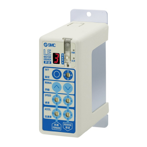
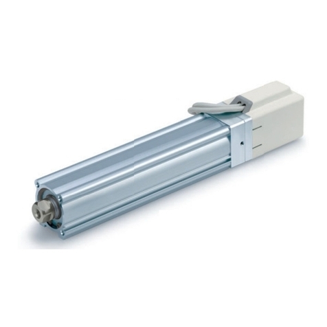
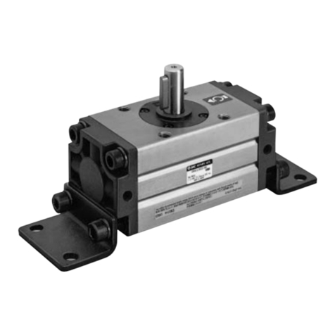
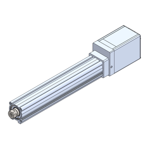
  9. SMC Networks LEG Series User manual

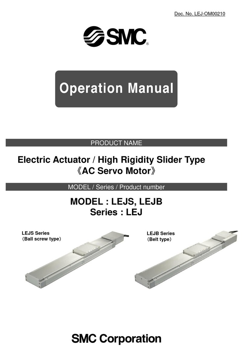
SMC Networks LEG Series User manual

This manual suits for next models

3

Other SMC Networks Controllers manuals
SMC Networks ASD F-A Series User manual

SMC Networks

SMC Networks ASD F-A Series User manual

SMC Networks JXC9H User manual

SMC Networks

SMC Networks JXC9H User manual

SMC Networks JXCEH User manual

SMC Networks

SMC Networks JXCEH User manual

SMC Networks MY3 Series User manual

SMC Networks

SMC Networks MY3 Series User manual

SMC Networks C96 Series User manual

SMC Networks

SMC Networks C96 Series User manual

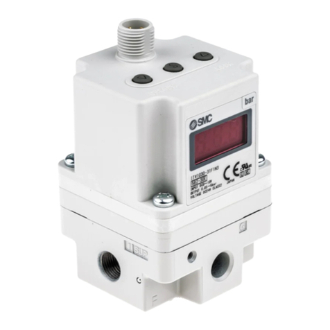
SMC Networks ITV 0 Series User manual

SMC Networks

SMC Networks ITV 0 Series User manual

SMC Networks EQY Series User manual

SMC Networks

SMC Networks EQY Series User manual

SMC Networks EtherNet/IP JXC91 Series Owner's manual

SMC Networks

SMC Networks EtherNet/IP JXC91 Series Owner's manual

SMC Networks ITV2050-IL20-X399 Series User manual

SMC Networks

SMC Networks ITV2050-IL20-X399 Series User manual

SMC Networks ITV1000-IL Series User manual

SMC Networks

SMC Networks ITV1000-IL Series User manual

SMC Networks EX260-SPR1/3 User manual

SMC Networks

SMC Networks EX260-SPR1/3 User manual

SMC Networks LEYG25M Manual

SMC Networks

SMC Networks LEYG25M Manual

SMC Networks PSE303-LBC User manual

SMC Networks

SMC Networks PSE303-LBC User manual

SMC Networks IR2000 Series User manual

SMC Networks

SMC Networks IR2000 Series User manual

SMC Networks ITV1000-52 Series User manual

SMC Networks

SMC Networks ITV1000-52 Series User manual

SMC Networks EQFS Series User manual

SMC Networks

SMC Networks EQFS Series User manual

SMC Networks ITV0000 Series User manual

SMC Networks

SMC Networks ITV0000 Series User manual

SMC Networks IR1000 Series User manual

SMC Networks

SMC Networks IR1000 Series User manual

SMC Networks 4011 Series User manual

SMC Networks

SMC Networks 4011 Series User manual

SMC Networks ITV1000-DE Series User manual
SMC Networks

SMC Networks ITV1000-DE Series User manual

SMC Networks IR320-A User manual

SMC Networks

SMC Networks IR320-A User manual

SMC Networks LECP2 Series User manual

SMC Networks

SMC Networks LECP2 Series User manual

SMC Networks ITV0000 Series User manual

SMC Networks

SMC Networks ITV0000 Series User manual

SMC Networks ITVX Series User manual

SMC Networks

SMC Networks ITVX Series User manual

Popular Controllers manuals by other brands

Sunricher SR-ZV9003T3-RGBW-US Installation

Sunricher

Sunricher SR-ZV9003T3-RGBW-US Installation

Ksenia intro Installation and configuration manual

Ksenia

Ksenia intro Installation and configuration manual

Inovance CAN200 Series manual

Inovance

Inovance CAN200 Series manual

Gauzy LC6 FLEX Controller Installation and operation guide

Gauzy

Gauzy LC6 FLEX Controller Installation and operation guide

Viking SLP-1 Technical practice

Viking

Viking SLP-1 Technical practice

CKD KBX-30E-U Series instruction manual

CKD

CKD KBX-30E-U Series instruction manual

Sharp Energy Sun Flux User manual & installation guide

Sharp Energy

Sharp Energy Sun Flux User manual & installation guide

Yamaha RCX40 user manual

Yamaha

Yamaha RCX40 user manual

AB Quality PowerFlex 400 Frames D-H Service bulletin

AB Quality

AB Quality PowerFlex 400 Frames D-H Service bulletin

Yamaha MJC8 owner's manual

Yamaha

Yamaha MJC8 owner's manual

AL-KO ATC operating instructions

AL-KO

AL-KO ATC operating instructions

Savant SmartControl 2 Deployment guide

Savant

Savant SmartControl 2 Deployment guide

GameSir T3S user manual

GameSir

GameSir T3S user manual

Kostal inveor operating manual

Kostal

Kostal inveor operating manual

Emerson Yarway 20-55 Operating and safety instructions

Emerson

Emerson Yarway 20-55 Operating and safety instructions

CoCo ACM-LV24 Quick installation guide

CoCo

CoCo ACM-LV24 Quick installation guide

Brooks SLA5810/20 Installation and operation manual

Brooks

Brooks SLA5810/20 Installation and operation manual

SIGMA TEK SR 011 Technical manual

SIGMA TEK

SIGMA TEK SR 011 Technical manual

manuals.online logo
manuals.online logoBrands
  • About & Mission
  • Contact us
  • Privacy Policy
  • Terms and Conditions

Copyright 2025 Manuals.Online. All Rights Reserved.

Max. weight of transferred object
Size: 25, 32, 40
For checking the limit and the intermediate signal
Max. acceleration/deceleration: 5000 mm/s2
¡ Restart from the last stop position is possible after
recovery of the power supply.
¡
Reduced maintenance (No need for control or replacement)
D-M9m/D-P3DWA
Size 25
75 kg
Size 32
100 kg
Size 40
150 kg
Application example
Electric Actuator
High Performance
High Rigidity Guide Rod Type
High performance
step motor controller
With internal battery-less
absolute encoder
Auto switches are mountable.
(In-line only)
Battery-less Absolute (Step Motor 24 VDC)
LEG Series
CAT.ES100-143A
∗Excludes auto
switches
For details, refer to
page 43 and onward.
Fully integrated the compact guide unit
for improved lateral load capacity
Variations
Improved rigidity
Lateral end load:
5times more∗1
∗1 Compared with the rod type, size 25, and 100 mm stroke
In-line motor type
Top side parallel motor type
Motor type Size
Max. weight of
transferred object
[kg]
Work load [kg] Positioning
repeatability
[mm]
Stroke
[mm]
Horizontal Vertical
Battery-less absolute
(Step motor 24 VDC) 25 75 20 24
±0.02
30
50
100
32 100 45 27
40 150 60 27
High Performance
Step Motor Controller
Higher acceleration and max. speed can be set
with the special controller.
JXC5H/6H Series p. 29 JXCEH/9H/PH Series p. 36
Parallel I/O
EtherCAT/EtherNet/IP™/
PROFINET
High Performance High Rigidity Guide Rod Type LEG Series
Battery-less Absolute (Step Motor 24 VDC)
1
Small auto switches can be directly
mounted on 2 surfaces.
113.5
mm
110 mm 185 mm
Size 25, 50 mm stroke
∗Motor mounting position: In-line only
For checking the limit and
the intermediate signal
Solid state auto switch
D-M9m
Magnetic field-resistant 2-color indicator
solid state auto switch
D-P3DWA
Width 110 mm xHeight 113.5 mm xOverall
length 185 mm
High Performance High Rigidity Guide Rod Type LEG Series
Battery-less Absolute (Step Motor 24 VDC)
2
1st screen
After entering the values,
they can be registered by pressing “SET.”
Step Axis 1
Step No. 0
Posn 123.45 mm
Speed 100 mm/s
2nd screen
1st screen
2nd screen
The operation status
can be checked.
Monitor Axis 1
Step No. 1
Posn 12.34 mm
Speed 10 mm/s
Step Axis 1
Step No. 0
Posn 50.00 mm
Speed 200 mm/s
Step Axis 1
Step No. 1
Posn 80.00 mm
Speed 100 mm/s
“Easy Mode” for simple setting
Example of checking the operation status
Simple setting allows for immediate use!
Start testing
Move for the
constant rate
Setting of jog
and speed of the
constant rate
Step data
setting
Jogging
<When a PC is used>
Controller setting software
¡ Step data setting, test drive,
jogging, and move for the
constant rate can be set and
operated on one screen.
Step Data Input Type JXC5H/6H Series
For immediate use, select “Easy Mode.”
<When a TB (teaching box) is used>
Teaching box screen
¡
The simple screen without scrolling
promotes ease of setting and operation.
¡
Choose an icon from the first screen
to select a function.
¡
Set the step data and
check the monitor on
the second screen.
¡
Data can be set by inputting
only the position and speed.
(Other conditions are preset.)
Example of setting the step data
p. 29
Step motor
(Servo/24 VDC)
JXC5H/6H
3
Controllers JXC mSeries
Menu Axis 1
Step data
Parameter
Test
Step
Axis 1
Step No.
0
Movement MOD
Test DRV Axis 1
Step No. 1
Posn 123.45 mm
Stop
Out mon Axis 1
BUSY[ ]
SVRE[ ]
SETON[ ]
“Normal Mode” for detailed setting
¡
Step data setting, parameter
setting, monitoring, teaching,
etc., are displayed in different
windows. Step data
setting window
Parameter
setting window
Monitoring window Teaching window
Controller setting software
<When a PC is used>
Main menu screen
Step data
setting screen Test screen
Monitoring screen
Select “Normal Mode” when detailed setting is required.
<When a TB (teaching box) is used>
Teaching box screen
¡
Step data can be set in detail.
¡
Signals and terminal status can be monitored.
¡Parameters can be set.
¡
JOG and constant rate movement, return to origin, test drive, and testing of forced output can be performed.
¡
Multiple step data can be
stored in the teaching box and
transferred to the controller.
¡
Continuous test drive by up to
5 step data
¡
Each function (step data setting,
test drive, monitoring, etc.) can
be selected from the main menu.
The actuator and controller are provided as a set. (They can be ordered separately as well.)
Confirm that the combination of the controller and actuator is correct.
<Check the following before use.>
qCheck the actuator label for the model number. This number should match that of the controller.
wCheck that the Parallel I/O configuration matches (NPN or PNP).
q w
Controller
Actuator
w
q
4
Controllers JXC mSeries
Function
Setting Items
TB: Teaching box PC: Controller setting software
: Can be set from TB Ver. 2.** (The version information is displayed on the initial screen.)
Item Step data input type
JXC5H/6H
Step data and parameter setting • Input from controller setting software (PC)
• Input from teaching box
Step data “position” setting
• Numerical value input from controller setting
software (PC) or teaching box
• Input numerical value
• Direct teaching
• JOG teaching
Number of step data 64 points
Operation command (I/O signal) Step No. [IN*] input ⇒[DRIVE] input
Completion signal [INP] output
Item Contents
Easy
Mode
Normal
Mode Step data
input type
JXC5H/6H
TB PC TB/PC
Step data
setting
(Excerpt)
Movement MOD
Selection of “absolute position” and “relative position”
V V Set at ABS/INC
Speed Transfer speed V V V Set in units of 1 mm/s
Position [Position]: Target position
[Pushing]: Pushing start position V V V Set in units of 0.01 mm
Acceleration/Deceleration
Acceleration/deceleration during movement V V V Set in units of 1 mm/s2
Pushing force Rate of force during pushing operation V V V Set in units of 1%
Trigger LV Target force during pushing operation V V Set in units of 1%
Pushing speed Speed during pushing operation V V Set in units of 1 mm/s
Moving force Force during positioning operation V V Set to 100%
Area output Conditions for area output signal to turn ON V V Set in units of 0.01 mm
In position [Position]: Width to the target position
[Pushing]: How much it moves during pushing V V Set to 0.5 mm or more
(Units: 0.01 mm)
Parameter
setting
(Excerpt)
Stroke (+) + side position limit   VSet in units of 0.01 mm
Stroke (−) − side position limit   VSet in units of 0.01 mm
ORIG direction Direction of the return to origin can be set.   VCompatible
ORIG speed Speed during return to origin   VSet in units of 1 mm/s
ORIG ACC Acceleration during return to origin   VSet in units of 1 mm/s2
Test
JOG V V V
Continuous operation at the set
speed can be tested while the
switch is being pressed.
MOVE V V
Operation at the set distance and speed from
the current position can be tested.
Return to ORIG V V V Compatible
Test drive Operation of the specified step data V V V
(Continuous operation)
Compatible
Forced output ON/OFF of the output terminal can be tested.   VCompatible
Monitor
DRV mon Current position, speed, force, and the speci-
fied step data can be monitored. V V V Compatible
In/Out mon Current ON/OFF status of the input and output
terminal can be monitored.   VCompatible
ALM Status
Alarm currently being generated can be confirmed.
V V V Compatible
ALM Log record Alarms generated in the past can be confirmed.   VCompatible
File Save/Load Step data and parameters can be saved, for-
warded, and deleted.   VCompatible
Other Language Can be changed to Japanese or English V V V Compatible
5
Controllers JXC mSeries
EtherCAT/EtherNet/IP™/PROFINET
Direct Input Type
Step Motor Controller/JXCmSeries
Application
Electric Actuators Air Cylinders
Two communication ports are provided.
Transition wiring of communication cables
Step no. defined operation: Operate using the preset
step data in the controller.
Numerical data defined operation: The actuator operates
using values such as position and speed from the PLC.
Numerical information, such as the current speed, current
position, and alarm codes, can be monitored on the PLC.
Two types of operation command
Numerical monitoring available
Fieldbus Network
PLC
p. 36
Both air and electric systems can be established
under the same protocol.
Communication protocols
PLC
EX260
6
Controllers JXC mSeries
System Construction/General Purpose I/O
VElectric actuator
PLC
VController∗1
To SI
To SI
To ENC
To CN2
∗1 Can be included as an option. Refer
to the “How to Order” page of the
actuator.
VActuator cable∗1
VTeaching box
(With 3 m cable)
LEC-T1-3mGm
Power supply
for I/O signal
24 VDC
Options
To CN5
VI/O cable
V USB cable
(A-mini B type)
(0.8 m)
PC
V
Communication cable for controller setting
V
Conversion cable∗2
P5062-5
(0.3 m)
Communication cable: JXC-W2A-C
USB cable : LEC-W2-U
Provided by the customer
Step data input type
JXC5H/6H
Part no.
LEC-CN5-m
Robotic cable
LE-CE-m
<Controller setting software/USB driver>
· Controller setting software
· USB driver (For JXC-W2A-C)
∗Download from SMC’s website:
https://www.smcworld.com
The conversion cable can
be used for connecting this
controller to the optional
teaching box [LEC-T1]
offered with the LEC series.
∗2 A conversion cable is also required to connect the JXCmH series controller and the LECmseries communication cable (LEC-W2A-C).
(A conversion cable is not required for the JXC-W2A-C.)
p. 35
p. 41
Communication cable V
(3 m)
p. 35
VConversion cable
p. 35
p. 35 p. 35
p. 35
p. 29
or
To PWR
VPower supply
plug
(Accessory)
p. 35
Power supply
for controller
24 VDC
Provided by the customer
7
Controllers JXC mSeries
To SI
To ENC
To MOT
To PWR
Actuator cable
LE-CE-
Robotic cable
Power supply
for controller
24 VDC
Provided by
the customer
Power supply
plug
(Accessory)
Teaching box
(With 3 m cable)
LEC-T1-3G
Options
Communication cable 
(3 m)
∗1 A conversion cable is also required to connect the JXCH series controller and the LECseries communication cable (LEC-W2A-C).
(A conversion cable is not required for the JXC-W2A-C.)
To SI
The conversion cable can
be used for connecting this
controller to the optional
teaching box [LEC-T1]
offered with the LEC series.
or
(A-mini B type)
(0.8 m)
USB cable

Communication cable for controller setting
Communication cable: JXC-W2A-C
USB cable : LEC-W2-U
<Controller setting software/USB driver>
· Controller setting software
· USB driver (For JXC-W2A-C)
∗Download from SMC’s website:
https://www.smcworld.com

Conversion cable
∗1
P5062-5
(0.3 m)
PC
Conversion
cable
p. 41
p. 40 p. 40 p. 40
p. 40
JXCEH JXC9H JXCPH
Electric actuator PLC
Provided by
the customer
PLC
Provided by
the customer
PLC
Provided by
the customer
p. 40
p. 36 p. 36 p. 36
p. 40
System Construction/Fieldbus Network
(EtherCAT/EtherNet/IP™/PROFINET Direct Input Type)
8
Controllers JXC mSeries
CONTENTS
Model Selection ……………………………………………………………………………………… p. 11
How to Order ………………………………………………………………………………………… p. 15
Specifications ………………………………………………………………………………………… p. 17
Construction …………………………………………………………………………………………… p. 18
Dimensions …………………………………………………………………………………………… p. 20
Auto Switch …………………………………………………………………………………………… p. 22
Specific Product Precautions ………………………………………………………………… p. 25
Battery-less Absolute Encoder Type Specific Product Precautions ……………………………………………………………………… p. 42
How to Order ………………………………………………………………………………………… p. 36
Specifications ………………………………………………………………………………………… p. 37
Dimensions …………………………………………………………………………………………… p. 38
Options ………………………………………………………………………………………………… p. 40
Actuator Cable ……………………………………………………………………………………… p. 41
How to Order ………………………………………………………………………………………… p. 29
Specifications ………………………………………………………………………………………… p. 29
Dimensions …………………………………………………………………………………………… p. 31
Options ………………………………………………………………………………………………… p. 35
Actuator Cable ……………………………………………………………………………………… p. 41
Controllers JXCmSeries p. 28
CE/UKCA/UL-compliance List ………………………………………………………………………………………………………………………… p. 43
High Performance
High Rigidity Guide Rod Type LEG Series p. 10
Battery-less Absolute (Step Motor 24 VDC)
High Performance Controller (Step Data Input Type) JXC5H/6H Series Battery-less Absolute (Step Motor 24 VDC)
High Performance Step Motor Controller JXCEH/9H/PH Series Battery-less Absolute (Step Motor 24 VDC)
9