SMC Sierra Monitor FS-IOT-BAC Series User guide

Document Revision: 4.C
T18620
BACnet IoT Gateway FS-IOT-BACX
Start-up Guide
APPLICABILITY & EFFECTIVITY
Effective for all systems manufactured after October 2020.

BACnet IoT Gateway Start-up Guide
Contact Information
Technical Support
Thank you for purchasing the BACnet IoT Gateway from MSA Safety.
Please call us for any technical support needs related to the FieldServer product.
MSA Safety
1991 Tarob Court
Milpitas, CA 95035
Website: www.sierramonitor.com
U.S. Support Information:
+1 408 964-4443
+1 800 727-4377
Email: [email protected]
EMEA Support Information:
+31 33 808 0590
Email: [email protected]

BACnet IoT Gateway Start-up Guide
Table of Contents
TABLE OF CONTENTS
1BACnet IoT Gateway Description.......................................................................................................7
2Equipment Setup .................................................................................................................................8
2.1 Physical Dimensions.......................................................................................................................8
2.1.1 FS-IOT-BAC Drawing..............................................................................................................8
2.1.2 FS-IOT-BACW Drawing ..........................................................................................................9
2.1.3 FS-IOT-BACA/V/F Drawing...................................................................................................10
2.2 Mounting.......................................................................................................................................11
2.3 Attaching the Antenna(s)..............................................................................................................11
2.4 FS-IOT-BACA/V/F: Inserting the SIM Card..................................................................................12
3Installing the BACnet IoT Gateway..................................................................................................13
3.1 FS-IOT-BAC/BACW: Connecting the R1 & R2 Ports...................................................................13
3.1.1 Wiring ....................................................................................................................................13
3.2 FS-IOT-BACA/V/F: Connecting the P1 Port.................................................................................14
3.2.1 Wiring ....................................................................................................................................14
3.3 10/100 Ethernet Connection Port.................................................................................................15
4Power up the BACnet IoT Gateway..................................................................................................16
5Connecting to the BACnet IoT Gateway..........................................................................................17
5.1 Using the FieldServer Toolbox.....................................................................................................17
5.2 Using a Web Browser...................................................................................................................17
6Setup Web Server Security...............................................................................................................18
6.1 Login to the FieldServer ...............................................................................................................18
6.2 Select the Security Mode..............................................................................................................20
6.2.1 HTTPS with Own Trusted TLS Certificate.............................................................................21
6.2.2 HTTPS with Default Untrusted Self-Signed TLS Certificate or HTTP with Built-in Payload
Encryption..............................................................................................................................21
7Configuring the BACnet IoT Gateway..............................................................................................22
7.1 Navigate to the Settings ...............................................................................................................22
7.2 Settings.........................................................................................................................................23
7.2.1 Network Settings ...................................................................................................................23
7.2.2 Local Settings –BACnet .......................................................................................................25
7.2.3 Remote Settings –Foreign Device Registration for BBMD Support.....................................26
8Using the BACnet IoT Gateway........................................................................................................27
8.1 BACnet Explorer...........................................................................................................................27
8.1.1 Discover the Device List........................................................................................................28
8.1.2 View Device Details and Explore Points/Parameters............................................................29
8.1.3 Explore All of a Device’s Points – Deep Explore...................................................................31
8.1.4 Checking Device Information –Device Info..........................................................................32
8.1.5 Edit the Present Value Field..................................................................................................33
8.2 Monitor View.................................................................................................................................35
8.2.1 Set Devices to Track.............................................................................................................35
8.2.2 Logging Data.........................................................................................................................36
8.3 Data Log Viewer...........................................................................................................................38
8.3.1 Graph Data Logging Information...........................................................................................38
8.3.2 Creating an Event Log...........................................................................................................41
8.4 Event Log......................................................................................................................................43
9SMC Cloud Setup...............................................................................................................................44
9.1 Create a New SMC Cloud Account..............................................................................................44
9.2 Login to SMC Cloud .....................................................................................................................51
10 MQTT Integration...............................................................................................................................53
10.1 MQTT Published Messages......................................................................................................53
10.2 Connect to MQTT......................................................................................................................54
10.3 Check the Status Window.........................................................................................................55

BACnet IoT Gateway Start-up Guide
Table of Contents
11 OpenVPN Setup .................................................................................................................................56
11.1 Setup Amazon AWS Server......................................................................................................56
11.2 Setup OpenVPN Cloud.............................................................................................................57
11.2.1 Configure the OpenVPN Server............................................................................................57
11.2.2 Login to the Server................................................................................................................57
11.2.3 Create a New User for the PC Connection...........................................................................58
11.2.4 Create a New User for the Device Connection.....................................................................60
11.3 Configure BACnet IoT Gateway for OpenVPN.........................................................................62
11.3.1 Download the DEVIC Configuration Profile...........................................................................62
11.3.2 Load the DEVICE OpenVPN Connection Profile onto the BACnet IoT Gateway.................63
11.4 Install the OpenVPN Client onto a Local PC ............................................................................64
11.4.1 Download the USER Configuration Profile............................................................................64
11.4.2 Load the USER OpenVPN Connection Profile onto the PC .................................................65
Appendix A Specifications.......................................................................................................................66
Appendix B References............................................................................................................................67
Appendix B.1 Understanding FDR..........................................................................................................67
Appendix B.2 Understanding BACnet BBMD and NAT Routing.............................................................67
Appendix C Troubleshooting...................................................................................................................69
Appendix C.1 Communicating with the BACnet IoT Gateway Over the Network...................................69
Appendix C.2 Lost or Incorrect IP Address.............................................................................................70
Appendix C.3 Viewing Diagnostic Information........................................................................................71
Appendix C.4 Checking Wiring and Settings ..........................................................................................71
Appendix C.5 LED Diagnostics for Communications Between BACnet IoT Gateway and Devices.......72
Appendix C.6 Taking a FieldServer Diagnostic Capture.........................................................................73
Appendix C.7 Updating Firmware ...........................................................................................................74
Appendix C.8 Kaspersky Endpoint Security 10.......................................................................................75
Appendix C.9 Wi-Fi and Cellular Signal Strength ...................................................................................76
Appendix C.10 Factory Reset Instructions..............................................................................................76
Appendix C.11 Internet Browser Software Support ................................................................................76
Appendix C.12 APN Table ......................................................................................................................76
Appendix C.13 Change Web Server Security Settings After Initial Setup ..............................................77
Appendix C.13.1 Change Security Mode ............................................................................................78
Appendix C.13.2 Edit the Certificate Loaded onto the FieldServer.....................................................79
Appendix C.14 Change User Management Settings ..............................................................................80
Appendix C.14.1 User Management....................................................................................................80
Appendix C.14.1.1 Create Users....................................................................................................81
Appendix C.14.1.2 Edit Users.........................................................................................................82
Appendix C.14.1.3 Delete Users.....................................................................................................83
Appendix C.14.2 Change FieldServer Password................................................................................84
Appendix C.15 System Status Button.....................................................................................................85
Appendix D Limited 2 Year Warranty......................................................................................................86

BACnet IoT Gateway Start-up Guide
List of Figures
LIST OF FIGURES
Figure 1: BACnet IoT Gateway FS-IOT-BAC Dimensions............................................................................8
Figure 2: BACnet IoT Gateway FS-IOT-BACW Dimensions........................................................................9
Figure 3: BACnet IoT Gateway FS-IOT-BAC/V/F Dimensions...................................................................10
Figure 4: DIN Rail........................................................................................................................................11
Figure 5: Insert SIM Card into the Micro SIM Card Slot –Label Side View (Left) and Top Down View
(Right) ..................................................................................................................................................12
Figure 6: R1 & R2 Connection Ports...........................................................................................................13
Figure 7: RS-485 P1 Connection Port ........................................................................................................14
Figure 8: Ethernet Connection....................................................................................................................15
Figure 9: Required Current Draw for the BACnet IoT Gateway..................................................................16
Figure 10: Connecting Power for FS-IOT-BAC...........................................................................................16
Figure 11: Connecting Power for FS-IOT-BACA/V/F..................................................................................16
Figure 12: Web Server Security Unconfigured Window .............................................................................18
Figure 13: Connection Not Private Warning ...............................................................................................18
Figure 14: Warning Expanded Text............................................................................................................19
Figure 15: FieldServer Login.......................................................................................................................19
Figure 16: Security Mode Selection Screen................................................................................................20
Figure 17: Security Mode Selection Screen –Certificate & Private Key....................................................21
Figure 18: Web App Landing Page.............................................................................................................22
Figure 19: Settings Tabs.............................................................................................................................22
Figure 20: Opt Out Warning Message........................................................................................................22
Figure 21: Configuration Button Functions .................................................................................................23
Figure 22: Network Settings –Common and IP Settings ...........................................................................23
Figure 23: Network Settings –Wi-Fi Client, Wi-Fi AP, and Cellular Settings.............................................24
Figure 24: Connection Settings...................................................................................................................25
Figure 25: Connection Parameters.............................................................................................................25
Figure 26: FDR Enabled Checkbox............................................................................................................26
Figure 27: FDR IP Fields.............................................................................................................................26
Figure 28: BACnet Explorer Page...............................................................................................................27
Figure 29: Discovery Window .....................................................................................................................28
Figure 30: Device List .................................................................................................................................28
Figure 31: Device Sub-items.......................................................................................................................29
Figure 32: Full Device Sub-items................................................................................................................29
Figure 33: Simplified Device Details...........................................................................................................30
Figure 34: Additional Device Details...........................................................................................................30
Figure 35: Highlighted Present Value.........................................................................................................33
Figure 36: Write Property Window..............................................................................................................33
Figure 37: Updated Present Value..............................................................................................................34
Figure 38: Selected Device Properties for Monitor View............................................................................35
Figure 39: Highlighted Monitor View Tab....................................................................................................35
Figure 40: Monitor View Showing Tracked Device Properties....................................................................36
Figure 41: Data Logging Window................................................................................................................36
Figure 42: Periodic Log Type......................................................................................................................36
Figure 43: Change of Value Log Type........................................................................................................36
Figure 44: Settings Window........................................................................................................................37
Figure 45: Edit Poll Interval Window...........................................................................................................37
Figure 46: Data Log Viewer Page...............................................................................................................38
Figure 47: Data Log Viewer Settings Window ............................................................................................38
Figure 48: Confirm Clear Logs Window......................................................................................................39
Figure 49: Data Log Viewer Graph.............................................................................................................39
Figure 50: Selected Portion of Data Log Viewer Graph..............................................................................40
Figure 51: Monitor View Device Properties.................................................................................................41
Figure 52: Event Settings Window..............................................................................................................41
Figure 53: Add Event Settings....................................................................................................................41
Figure 54: Event Settings Window with Added Events...............................................................................42
Figure 55: Monitor View Device Properties with Updated Status...............................................................42
Figure 56: Event Log Page Showing Added Events...................................................................................43

BACnet IoT Gateway Start-up Guide
List of Figures
Figure 57: BACnet IoT Gateway Landing Page –SMC Cloud Tab............................................................44
Figure 58: Registration Information Page...................................................................................................44
Figure 59: SMC Cloud Connection Problems Message.............................................................................45
Figure 60: SMC Cloud Registration –Installer Details ...............................................................................46
Figure 61: SMC Cloud Registration –Site Details......................................................................................46
Figure 62: SMC Cloud Registration –Gateway Details..............................................................................47
Figure 63: SMC Cloud Registration –SMC Cloud Account........................................................................47
Figure 64: Device Registered for SMC Cloud.............................................................................................48
Figure 65: Welcome to SMC Cloud Email ..................................................................................................49
Figure 66: Setting User Details...................................................................................................................50
Figure 67: SMC Cloud Login Page.............................................................................................................51
Figure 68: SMC Cloud Privacy Policy.........................................................................................................51
Figure 69: SMC Cloud Landing Page.........................................................................................................52
Figure 70: Specifications.............................................................................................................................66
Figure 71: BBMD Scenario 1 –Interconnected IP Network........................................................................67
Figure 72: BBMD Scenario 2 –NAT Routing..............................................................................................68
Figure 73: Ethernet Port Location...............................................................................................................70
Figure 74: Error Messages Screen.............................................................................................................71
Figure 75: Diagnostic LEDs ........................................................................................................................72
Figure 76: Kaspersky ES10 Settings..........................................................................................................75
Figure 77: Web Anti-Virus Trusted URLs....................................................................................................75
Figure 78: Wi-Fi & Cellular Signal Strength Listing.....................................................................................76
Figure 79: Cellular Provider APN................................................................................................................76
Figure 80: FS-GUI Page .............................................................................................................................77
Figure 81: FS-GUI Security Setup..............................................................................................................78
Figure 82: FS-GUI Security Setup –Certificate Loaded.............................................................................79
Figure 83: FS-GUI User Management........................................................................................................80
Figure 84: Create User Window..................................................................................................................81
Figure 85: Setup Users...............................................................................................................................82
Figure 86: Edit User Window ......................................................................................................................82
Figure 87: Setup Users...............................................................................................................................83
Figure 88: User Delete Warning .................................................................................................................83
Figure 89: FieldServer Password Update via FS-GUI................................................................................84

BACnet IoT Gateway Start-up Guide
Page 7 of 86
1 BACNET IOT GATEWAY DESCRIPTION
The BACnet IoT Gateway provides a connection from BACnet devices and networks to the cloud. This is
achieved via a discovery tool built into the hardware for any BACnet/IP or BACnet MS/TP network without
any additional dongles or installations needed. BBMD BACnet network discovery is also supported.
The BACnet IoT Gateway comes in three model types. The FS-IOT-BAC model offers two RS-485 ports
and one Ethernet 10/100 port. The FS-IOT-BACW model has two RS-485 ports, one Ethernet 10/100 port
and supports Wi-Fi network connection. The FS-IOT-BACA, FS-IOT-BACV and FS-IOT-BACF models offer
cellular connections for the chosen carrier (AT&T, Verizon or Vodafone), one RS-485 port, one Ethernet
10/100 port and supports Wi-Fi network connection.
Additionally, Wi-Fi models act as a Wi-Fi access point for modern web-based configuration and remote
access from any mobile device without user restrictions.
The BACnet IoT Gateway also includes Monitor View, Data Log Viewer, Virtual Points and Event Log data
analysis features that allow tracking and logging of individual device data points across the connected
network in real-time.
The BACnet IoT Gateway is cloud ready and connects with MSA Safety’s SMC Cloud.
NOTE: For SMC Cloud information, refer to the SMC Cloud Start-up Guide online through the
Sierra Monitor website.
NOTE: The latest versions of instruction manuals, driver manuals, configuration manuals and
support utilities are available online through the Sierra Monitor website.

BACnet IoT Gateway Start-up Guide
Page 8 of 86
2 EQUIPMENT SETUP
2.1 Physical Dimensions
2.1.1 FS-IOT-BAC Drawing
Figure 1: BACnet IoT Gateway FS-IOT-BAC Dimensions
R1 Serial Port
Power Port
R2 Serial Port

BACnet IoT Gateway Start-up Guide
Page 9 of 86
2.1.2 FS-IOT-BACW Drawing
Figure 2: BACnet IoT Gateway FS-IOT-BACW Dimensions
R1 Serial Port
Power Port
Wi-Fi Antenna
Socket
R2 Serial Port

BACnet IoT Gateway Start-up Guide
Page 10 of 86
2.1.3 FS-IOT-BACA/V/F Drawing
Figure 3: BACnet IoT Gateway FS-IOT-BAC/V/F Dimensions
P1 Serial Port
Power Port
Cellular Antennas
Cellular Antenna
Sockets

BACnet IoT Gateway Start-up Guide
Page 11 of 86
2.2 Mounting
The BACnet IoT Gateway can be mounted using the DIN rail mounting bracket on the back of the unit.
2.3 Attaching the Antenna(s)
NOTE: This Section does not apply to the FS-IOT-BAC model BACnet IoT Gateway.
Wi-Fi Antenna:
If using the FS-IOT-BACW (Wi-Fi) model, screw in the Wi-Fi antenna to the socket on the front of the unit.
For the location of the socket, see Figure 2.
Cellular Antennas:
If using the FS-IOT-BACA/V/F models, screw in the long cellular antennas into the sockets on the top and
the front of the unit as shown in Figure 3.
Din Rail
Bracket
Figure 4: DIN Rail

BACnet IoT Gateway Start-up Guide
Page 12 of 86
2.4 FS-IOT-BACA/V/F: Inserting the SIM Card
NOTE: A micro 4G SIM card must be purchased from an AT&T, Verizon or Vodafone cellular
provider to set up cellular functionality and create a data plan for the ProtoAir. SIM card
vendor contact information is available at the end of the section.
Insert the SIM card into the Micro SIM card slot with the chip on the SIM card facing away from
the cellular antenna as shown below.
See Section 7 to complete cellular setting configuration.
SIM Card Vendor Contact Information:
Verizon
A business contract is required to purchase a Verizon SIM card. The IMEI of the ProtoAir is required to
purchase the Verizon SIM card.
AT&T
Please call AT&T Customer Service at 800.331.0500 or find the nearest AT&T store.
Figure 5: Insert SIM Card into the Micro SIM Card Slot –
Label Side View (Left) and Top Down View (Right)

BACnet IoT Gateway Start-up Guide
Page 13 of 86
3 INSTALLING THE BACNET IOT GATEWAY
3.1 FS-IOT-BAC/BACW: Connecting the R1 & R2 Ports
NOTE: Ensure RS-485 is selected for R1 by checking that the number 4 DIP Switch is set to the
left side.
Connect to the 3-pin connector(s) as shown below.
The following baud rates are supported for both ports:
9600, 19200, 38400, 76800
3.1.1 Wiring
RS-485
BMS RS-485
Wiring
Gateway Pin
Assignment
RS-485 +
TX +
RS-485 -
RX -
GND
GND
NOTE: Use standard grounding principles for GND.
TX+ RX- GND
+ - GND
Figure 6: R1 & R2 Connection Ports

BACnet IoT Gateway Start-up Guide
Page 14 of 86
3.2 FS-IOT-BACA/V/F: Connecting the P1 Port
NOTE: Ensure RS-485 is selected by checking that the number 4 DIP Switch is set to the left side.
Connect to the 3-pin connector as shown below.
The following Baud Rates are supported on the P1 Port:
9600, 19200, 38400, 76800
3.2.1 Wiring
RS-485
BMS RS-485 Wiring
BACnet IoT Gateway
Pin Assignment
RS-485 +
TX +
RS-485 -
RX -
GND
GND
NOTE: Use standard grounding principles for GND.
Figure 7: RS-485 P1 Connection Port
TX+ RX- GND

BACnet IoT Gateway Start-up Guide
Page 15 of 86
3.3 10/100 Ethernet Connection Port
The Ethernet Port is used both for BACnet/IP communications and for configuring the BACnet IoT Gateway
via the Web App. To connect the BACnet IoT Gateway, either connect the PC to the Gateway’s Ethernet
port or connect the Gateway and PC to an Ethernet switch. Use Cat-5 cables for the connection.
NOTE: The Default IP Address of the BACnet IoT Gateway is 192.168.2.101, Subnet Mask is
255.255.255.0.
Figure 8: Ethernet Connection
Ethernet Port

BACnet IoT Gateway Start-up Guide
Page 16 of 86
4 POWER UP THE BACNET IOT GATEWAY
Check power requirements in the table below:
Power Requirement for BACnet IoT Gateway External Gateway
Current Draw Type
BACnet IoT Gateway Family
12VDC
24VDC
24VAC
FS-IOT-BAC/BACW (Typical)
250mA
125mA
125mA
FS-IOT-BACA/V/F (Typical)
320mA
185mA
N/A
FS-IOT-BACA/V/F (Maximum)
670mA
390mA
N/A
NOTE: These values are ‘nominal’ and a safety margin should be added to the power
supply of the host system. A safety margin of 25% is recommended.
Figure 9: Required Current Draw for the BACnet IoT Gateway
Apply power to the BACnet IoT Gateway as shown below. Ensure that the power supply used complies
with the specifications provided. Ensure that the cable is grounded using the FG or “Frame GND” terminal.
•The FS-IOT-BAC/BACW BACnet IoT Gateway accepts 9-30VDC or 24VAC.
•The FS-IOT-BACA/V/F BACnet IoT Gateways accept 12-24VDC.
Figure 10: Connecting Power for FS-IOT-BAC
FG –+
Figure 11: Connecting Power for FS-IOT-BACA/V/F
FG –+

BACnet IoT Gateway Start-up Guide
Page 17 of 86
5 CONNECTING TO THE BACNET IOT GATEWAY
The FieldServer Toolbox Application can be used to discover and connect to the BACnet IoT Gateway on
a local area network. To manually connect to the BACnet IoT Gateway using the Toolbox, click on the
plus icon ( ) and enter the IP Address, or enter the Internet IP Address into a web browser.
5.1 Using the FieldServer Toolbox
•Install the Toolbox application from the USB drive or get it from the Sierra Monitor website.
•Use the Toolbox application to find the BACnet IoT Gateway IP Address and launch the Web App
(by clicking the Connect button).
5.2 Using a Web Browser
Open a Web Browser and input the BACnet IoT Gateway’s IP Address. The Default IP Address of the
BACnet IoT Gateway is 192.168.2.101, Subnet Mask is 255.255.255.0. If the PC and the BACnet IoT
Gateway are on different IP Networks, assign a Static IP Address to the PC on the 192.168.2.X network.
NOTE: Check Appendix C.11 for supported browsers.
+

BACnet IoT Gateway Start-up Guide
Page 18 of 86
6 SETUP WEB SERVER SECURITY
6.1 Login to the FieldServer
The first time the FieldServer GUI is opened in a browser, the IP Address for the gateway will appear as
untrusted. This will cause the following pop-up windows to appear.
•When the Web Server Security Unconfigured window appears, read the text and choose whether
to move forward with HTTPS or HTTP.
•When the warning that “Your connection is not private” appears, click the advanced button on the
bottom left corner of the screen.
Figure 13: Connection Not Private Warning
Figure 12: Web Server Security Unconfigured Window

BACnet IoT Gateway Start-up Guide
Page 19 of 86
•Additional text will expand below the warning, click the underlined text to go to the IP Address. In
the Figure 14 example this text is “Proceed to 10.40.50.94 (unsafe)”.
•When the login screen appears, put in the Username (default is “admin”) and the Password (found
on the label of the FieldServer).
NOTE: There is also a QR code in the top right corner of the FieldServer label that shows the
default unique password when scanned.
NOTE: A user has 5 attempts to login then there will be a 10-minute lockout. There is no timeout
on the FieldServer to enter a password.
NOTE: To create individual user logins, go to Appendix C.14.
Figure 15: FieldServer Login
Figure 14: Warning Expanded Text

BACnet IoT Gateway Start-up Guide
Page 20 of 86
6.2 Select the Security Mode
On the first login to the FieldServer, the following screen will appear that allows the user to select which
mode the FieldServer should use.
NOTE: Cookies are used for authentication.
NOTE: To change the web server security mode after initial setup, go to Appendix C.13.
The sections that follow include instructions for assigning the different security modes.
Figure 16: Security Mode Selection Screen
This manual suits for next models
5
Table of contents
Other SMC Sierra Monitor Gateway manuals
SMC Sierra Monitor
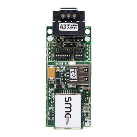
SMC Sierra Monitor FieldServer ProtoNode User manual
SMC Sierra Monitor
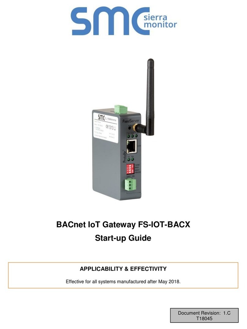
SMC Sierra Monitor FS-IOT-BACX User guide
SMC Sierra Monitor
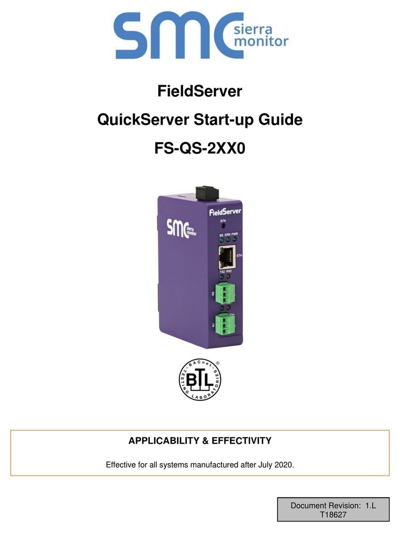
SMC Sierra Monitor FieldServer QuickServer FS-QS-2 0 Series User manual
SMC Sierra Monitor
SMC Sierra Monitor ProtoNode FPC-N54 User guide
SMC Sierra Monitor
SMC Sierra Monitor FieldServer FS-8704-23 Release note
SMC Sierra Monitor
SMC Sierra Monitor ProtoAir FPA-W34 User guide

SMC Sierra Monitor
SMC Sierra Monitor Pure Humidifier ProtoAir FPA-W44 User guide
SMC Sierra Monitor
SMC Sierra Monitor FieldServer FS-QS-2 10 Series User guide
