Smeg SE70SGHLK User manual

Contents
1. INSTRUCTIONS FOR SAFE AND PROPER USE________________ 4
2. POSITIONING THE COOKTOP ______________________________ 6
3. ELECTRICAL CONNECTION _______________________________ 8
4. GAS CONNECTION _______________________________________ 9
5. ADAPTATION TO DIFFERENT TYPES OF GAS _______________ 11
6. FINAL OPERATIONS_____________________________________ 14
7. USING THE COOKTOP ___________________________________ 16
8. CLEANING AND MAINTENANCE ___________________________ 18
THESE INSTRUCTIONS ARE VALID ONLY FOR END USER COUNTRIES WHOSE
IDENTIFICATION SYMBOLS APPEAR ON THE COVER OF THIS MANUAL.
INSTRUCTIONS FOR THE INSTALLER: these instructions are for the
qualified technician who must carry out a suitable check of the gas
system, install the appliance, make it operational and carry out an
inspection test.
INSTRUCTIONS FOR THE USER: these instructions contain user
advice, descriptions of the commands and the correct procedures for
cleaning and maintenance of the appliance.
3

Introduction
1. INSTRUCTIONS FOR SAFE AND PROPER USE
THIS MANUAL IS AN INTEGRAL PART OF THE APPLIANCE AND
THEREFORE MUST BE KEPT IN ITS ENTIRETY AND IN AN ACCESSIBLE
PLACE FOR THE WHOLE WORKING LIFE OF THE COOKTOP. WE
ADVISE READING THIS MANUAL AND ALL THE INSTRUCTIONS
THEREIN BEFORE USING THE COOKTOP. ALSO KEEP THE SUPPLIED
SET OF NOZZLES. INSTALLATION MUST BE CARRIED OUT BY
QUALIFIED PERSONNEL IN ACCORDANCE WITH THE REGULATIONS IN
FORCE. THIS APPLIANCE IS INTENDED FOR DOMESTIC USE AND
CONFORMS TO THE CURRENT REGULATIONS IN FORCE. THE
APPLIANCE HAS BEEN BUILT TO CARRY OUT THE FOLLOWING
FUNCTIONS: COOKING AND HEATING-UP OF FOOD. ALL OTHER USES
ARE CONSIDERED IMPROPER.
THE MANUFACTURER DECLINES ALL RESPONSIBILITY FOR
IMPROPER USE.
DO NOT LEAVE THE PACKING IN THE HOME ENVIRONMENT.
SEPARATE THE VARIOUS WASTE MATERIALS AND TAKE THEM TO THE
NEAREST SPECIALIZED WASTE COLLECTION CENTER.
THE ELECTRICAL SYSTEM MUST BE GROUNDED ACCORDING TO THE
METHODS REQUIRED BY THE SAFETY STANDARDS.
THE PLUG TO BE CONNECTED TO THE POWER CABLE AND THE
SOCKET MUST BE THE SAME TYPE AND MUST CONFORM TO
CURRENT REGULATIONS.
NEVER UNPLUG BY PULLING ON THE POWER CABLE.
IMMEDIATELY AFTER INSTALLATION BRIEFLY INSPECT THE
COOKTOP, FOLLOWING THE INSTRUCTIONS BELOW. IF THE
APPLIANCE DOES NOT FUNCTION, DISCONNECT IT FROM THE POWER
SUPPLY AND CALL THE NEAREST TECHNICAL ASSISTANCE CENTER.
NEVER ATTEMPT TO REPAIR THE APPLIANCE.
ALWAYS CHECK THAT THE CONTROL KNOBS ARE IN THE POSITION
"ZERO" (OFF) WHEN YOU FINISH USING THE COOKTOP.
THE IDENTIFICATION PLATE, WITH TECHNICAL DATA, SERIAL NUMBER
AND MARKING IS CLEARLY VISIBLE UNDER THE CASING.
THE PLATE ON THE CASING MUST NOT BE REMOVED.
4

Introduction
BEFORE CONNECTING THE APPLIANCE, MAKE SURE THAT IT HAS
BEEN REGULATED FOR THE TYPE OF GAS THAT WILL FEED IT,
CHECKING THE LABEL UNDER THE CASING.
DO NOT USE PANS WITHOUT PERFECTLY SMOOTH AND FLAT
BOTTOMS ON THE COOKTOP GRATES.
DO NOT USE RECIPIENTS OR GRIDDLE PLATES THAT EXTEND
BEYOND THE EXTERNAL PERIMETER OF THE COOKTOP.
THE COOKTOP IS TO BE USED BY ADULTS ONLY. DO NOT LET
UNSUPERVISED CHILDREN PLAY WITH THE COOKTOP.
THIS APPLIANCE IS MARKED ACCORDING TO THE EUROPEAN
DIRECTIVE 2002/96/EC ON WASTE ELECTRICAL AND ELECTRONIC
EQUIPMENT (WEEE).
THIS GUIDELINE IS THE FRAME OF A EUROPEAN-WIDE VALIDITY OF
RETURN AND RECYCLING ON WASTE ELECTRICAL AND ELECTRONIC
EQUIPMENT.
The manufacturer declines all responsibility for damage to
persons or things caused by non-observance of the above
prescriptions or by interference with any part of the appliance or by
the use of non-original replacement parts.
5

Instructions for the installer
6
2. POSITIONING THE COOKTOP
The following operation requires building and/or carpentry work that must
be carried out by a skilled tradesman.
The cooktop may be installed on various materials, such as masonry,
metal, solid wood, plastic laminated wood etc. as long as they are heat
resistant (T = 90°C - 194° F).
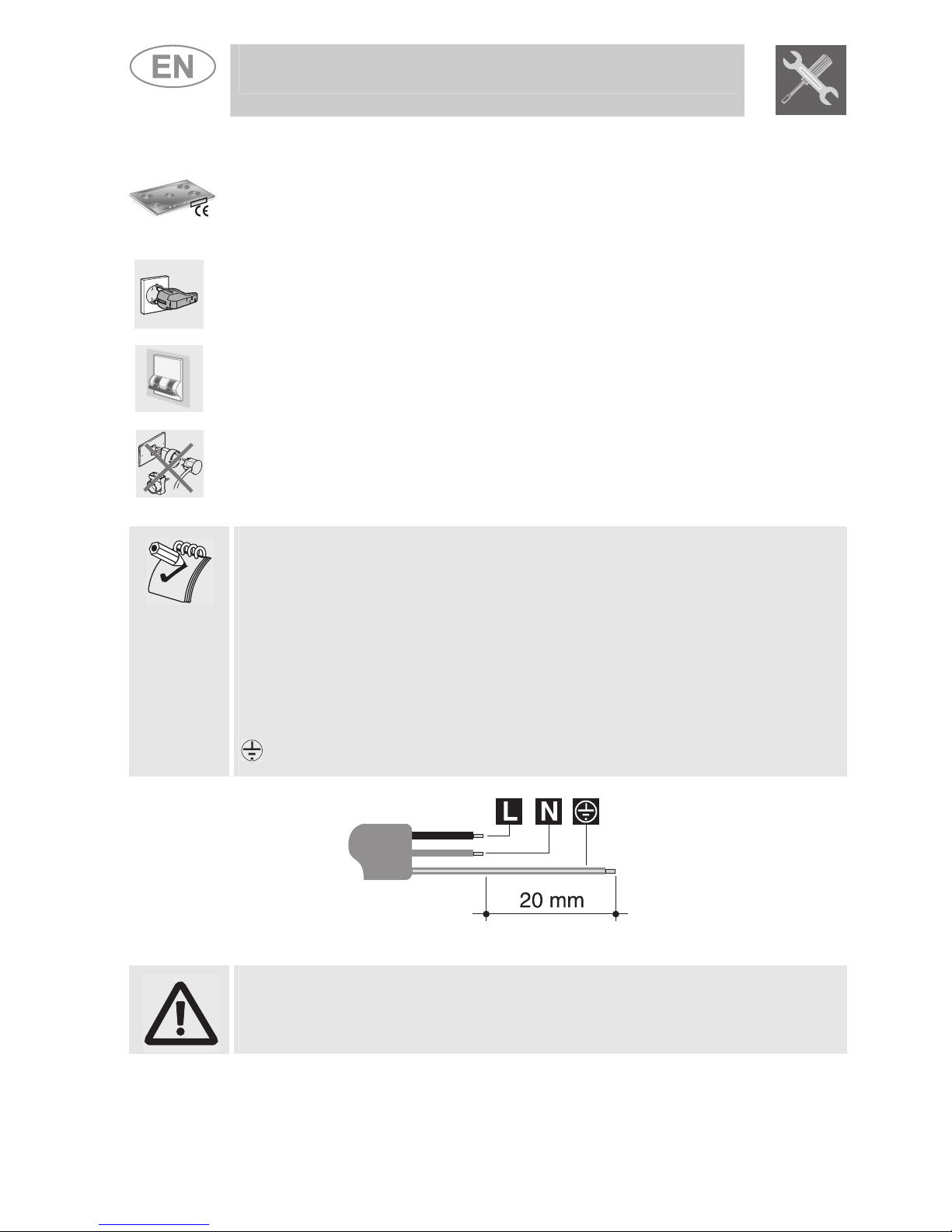
Never use silicone or other insulating products when installing the
appliance; only use the rubber gasket provided.
2.1.1 Attachment to the support structure
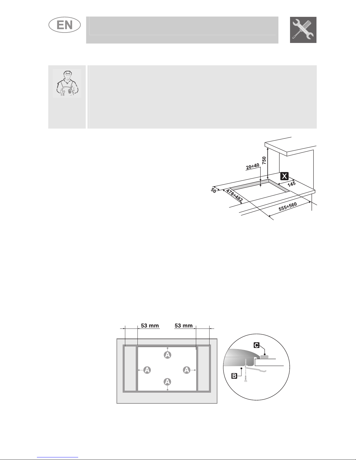
Create an opening in the top surface
of the counter with the dimensions
shown in the figure, keeping a
minimum distance of 50 mm (2
inches) from the rear edge.
This appliance is classified "type Y"
with regard to risks against fire and
can be positioned adjacent to walls
that are higher than the work
surface, provided that a distance of
145 mm (5.7 in) is respected (as
shown in the figure) in order to
prevent damage due to overheating.
Make sure there is a minimum of 750 mm (30 in) between the burner
flames and any shelf that may be installed directly above them.
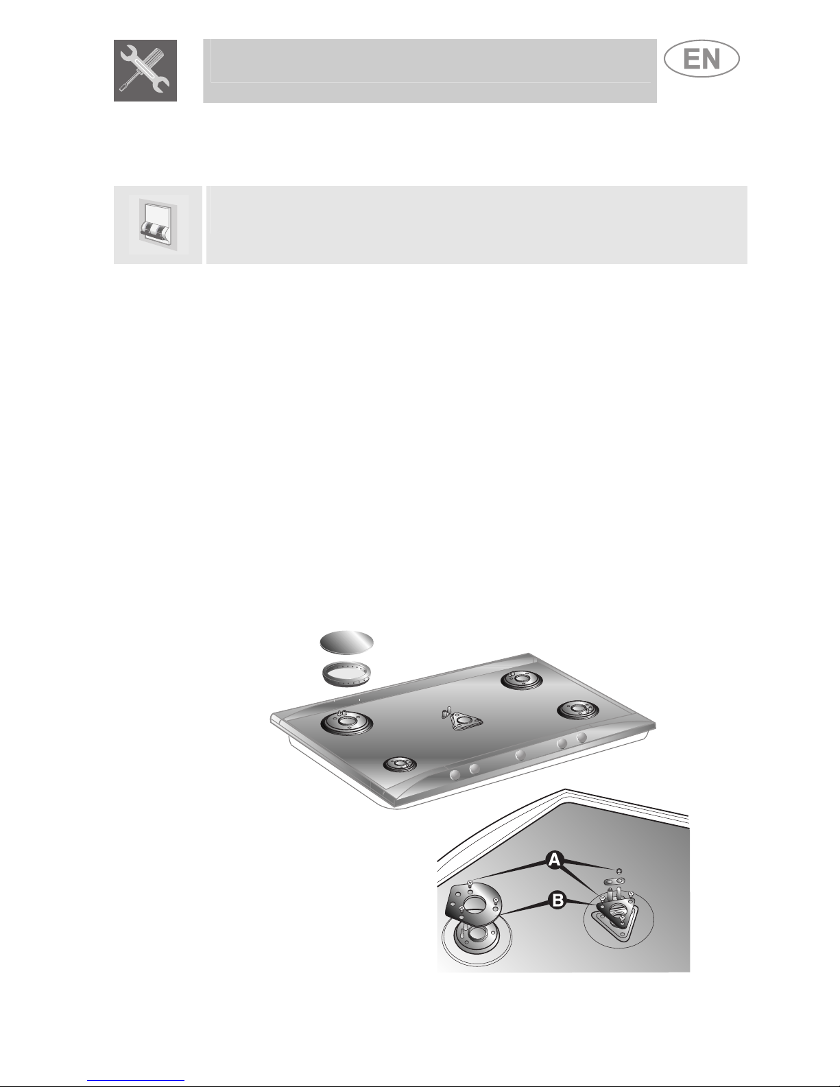
Carefully position the insulation gasket (supplied) on the external
perimeter of the hole made in the top surface (see figures below) and try
to make it stick to the entire surface by applying light pressure with your
hands. Refer to the coordinates shown in the figure, keeping in mind that
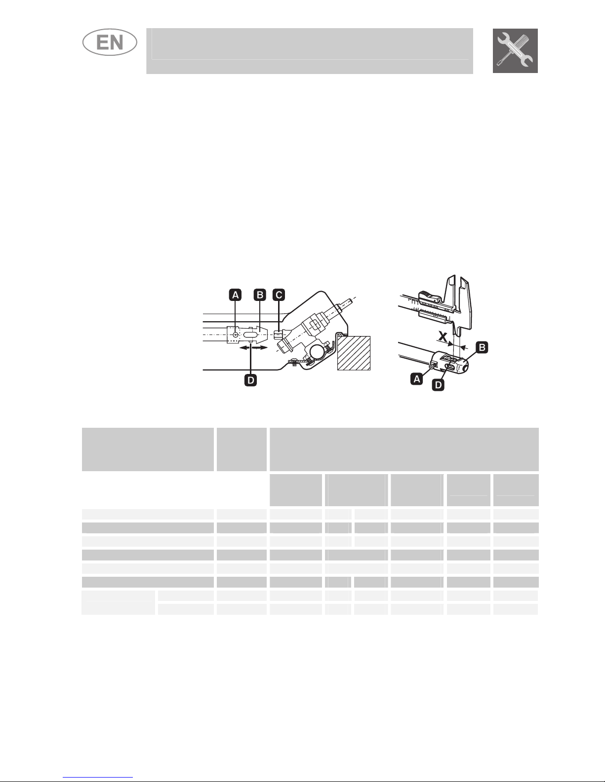
sides Ashould be adjacent to the hole. Secure the cooktop to the counter
with brackets B(supplied). Carefully trim any excess from border Cof the
gasket. The distances in the following drawing refer to the hole on the
inner side of the gasket.

Instructions for the installer
If installing on a hollow compartment with doors, a separating panel
must be placed under the cooktop. Keep a minimum distance of 10 mm
(0.39 in) between the bottom of the unit and the panel’s surface. The
panel must be able to be easily removed to allow access in the event of
technical service.
7

Instructions for the installer
8
3. ELECTRICAL CONNECTION
Make sure that the voltage and capacity of the power line conform to the
data shown on the plate located under the casing. Do not remove this
plate for any reason.
The plug on the end of the supply cable and the wall socket must be the
same type and conform to the current electrical system regulations.
Check that the power line is adequately grounded.
On the power line, install an omnipolar cut-off device with contact cut-off
distance greater than or equal to 3 mm (0.11 in), located in an easily
accessible position near the appliance.
Do not use reducers, adapters or shunts.
If the power cable is replaced, the wire section on the new cable must
not be less than 0.75 mm2(3 x 0.75 cable), keeping in mind that the
ground wire (yellow-green) on the end to be connected to the cooktop
must be at least 20 mm (0.78 inch) longer. Use only H05V2V2-F cable or
similar which has a maximum temperature rating of 90°C (194° F). Any
replacement needed should be carried out by a specialized technician who
should perform the mains connections according to the following diagram.
L= brown
N= blue
= yellow-green
The manufacturer declines all responsibility for any damage to
persons or property caused by non-observance of the above instructions
or deriving from the tampering of even a single part of the cooktop.

Instructions for the installer
4. GAS CONNECTION
Connection to the gas mains may be made with a rigid copper pipe or
with a flexible pipe and conforming to the provisions defined by standard
regulations in force.
To facilitate connection, fitting Aon the rear of the appliance may be
adjusted laterally. For this purpose, loosen hexagon nut B, turn fitting A
to the desired position, and retighten hexagon nut B(tightness is ensured
by a biconical brass ring). Use a soapy solution to check for proper
tightness. Never use an open flame.
The cooktop has been inspected for LPG gas G30/G31 (3+) at a
pressure of 28/37 mbar. For use with other types of gases, see Section
“5. ADAPTATION TO DIFFERENT TYPES OF GAS”. The gas intake
fitting is ½” gas external threaded (ISO 228-1).
Connection with rigid copper pipe:
the connection to the gas mains must
not put stress of any kind on the
cooktop.
Connection may be made by using
biconical adapter Dwith insertion of
gasket C(supplied).
Connection with flexible pipe: use
only flexible pipes conforming to
standard regulations in force, inserting
gasket C(supplied) between fitting A
and flexible pipe E.
The flexible pipe has to be installed so that pipe length does not exceed
1.5 meters of maximum extension. Make sure that the pipes do not touch
any moving parts or become damaged.
9

Instructions for the installer
10
4.1 Connection to LPG
Use a pressure regulator and make the connection to the tank according
to the provisions of standards regulations in force. Make sure that feed
pressure conforms to the levels shown in the table in paragraph “5.2
Regulation for LPG”.
4.2 Room ventilation
The cooktop should only be installed in rooms with permanent
ventilation, as required by the standard regulations in force The room in
which the hob is installed must have sufficient air flow to satisfy the
requirements of normal gas combustion and of necessary air exchange
in the room. The air intakes, protected by screens, must be appropriately
sized (regulations in force) and positioned so that they are not blocked in
any way.
The room where the oven is installed should be suitably ventilated to
avoid overheating or excess humidity produced by cooking. If it will be
used for a lengthy amount of time, a window should be opened or the
speed of any fans should be increased.
4.3 Discharge of combustion products
Discharge of combustion products must be guaranteed by means of
hoods connected to a natural draught flue with certain efficiency, or by
means of forced aspiration.
An efficient aspiration system requires careful planning by a specialist
capable of installing it, respecting the positions and distances prescribed
by the standards. After installation, the installer must issue a certificate of
conformity.

Instructions for the installer
5. ADAPTATION TO DIFFERENT TYPES OF GAS
Before performing any cleaning or maintenance work, unplug the
appliance from the electric socket.
The cooktop has been inspected for LPG gas G30/G31 (3+) at a
pressure of 28/37 mbar. For functioning with other types of gas the
nozzles must be replaced and the primary air adjusted.
To replace the nozzles and regulate the burners, you have to remove the
top as described in the following paragraph.
5.1 Removing the cooktop
1. Remove all the knobs, the grates, the burner caps and the burner
rings;
2. remove the screws and the nuts Aholding the burner supports;
3. remove plates B;
4. lift the cooktop from its seat;
5. replace the burner nozzles in accordance with the reference gas
chart;
6. regulate the primary air as described in paragraph “5.2 Regulation
for LPG”.
11

Instructions for the installer
12
5.2 Regulation for LPG
Loosen screw Aand push support Ball the way. Use a double head
wrench to remove nozzle Cand assemble the suitable nozzle, following
the instructions indicated in the reference charts for the type of gas to be
used. The screwing torque of the nozzle should never exceed 3 Nm.
Reposition support Bso that nozzle Cis perfectly covered.
Move the Venturi tube Dto regulate the air flow until distance "X"
indicated in the chart in paragraph "5.4 Regulation of primary air” is
reached and then fasten the tube with screw A. After the regulations have
been carried out, restore the seals with sealing wax or equivalent
material.
Burner
Rated
heating
capacity
(kW)
LPG – G30/G31 28/37 mbar
Nozzle
diameter
1/100 mm
By-pass
mm
1/100
Reduced
capacity
(W)
Capacity
g/h G30
Capacity
g/h G31
Auxiliary (1) 1.05 48 30 33 (*) 380 76 75
Semi-fast (2) 1.65 62 30 33 (*) 380 120 118
Average fast (3) 2.55 76 37 40 (*) 650 185 182
Large fast (4) 3.1 85 43 750 225 222
Triple crown (5) 3.9 95 65 1700 283 279
Triple crown (6) 3.3 87 55 65 (*) 1200 240 236
internal (7) 1.15 48 30 33 (*) 380 84 82Double crown
external (7) 3.8 93 55 65 (*) 1200 276 271
(*) By-pass value for valveless appliances.

Instructions for the installer
5.3 Regulation for natural gas
The cooktop has been inspected for LPG gas G30/G31 (3+) at a
pressure of 28/37 mbar. To allow the appliance to work with this type of
gas, perform the same operations described in paragraph “5.2 Regulation
for LPG”, but choose the nozzles and regulate the primary air for natural
gas, as shown in the following table and in paragraph “5.4 Regulation of
primary air”. After the regulations have been carried out, restore the seals
with sealing wax or equivalent material.
Burner
Rated heating
capacity
(kW)
Natural gas – G20 20 mbar
Nozzle diameter
1/100 mm
Reduced capacity
(W)
Auxiliary (1) 1.05 73 380
Semi-fast (2) 1.65 92 380
Average fast (3) 2.55 115 750
Large fast (4) 3.1 126 800
Triple crown (5) 3.9 140 1400
Triple crown (6) 3.3 130 1200
internal (7) 1.05 73 380Double crown
external (7) 3.9 140 1200
5.4 Regulation of primary air
Referred to distance “X” in mm.
BURNER G20
20 mbar
G30/G31
28/37 mbar
Auxiliary (1) 1.5 1
Semi-fast (2) 1.5 1.5
Average fast (3) 1.0 1.5
Large fast (4) 2.5 10.0
Triple crown (5) 2.0 3.5
Triple crown (6) 2.0 2.5
internal (7) 4.5 6.0Double
crown external (7) 3.0 10.0
To identify the burners on your cooktop, refer to the drawings in section “6.3
Arrangement of burners on the cooktop“
13

Instructions for the installer
14
6. FINAL OPERATIONS
Having carried out the above adjustments, reassemble the appliance
following the instructions in paragraph “5.1 Removing the hob” in reverse
order.
6.1 Minimum level adjustment for natural gas
Replace the parts on the burner and turn the
knobs on the gas tap valves.
Light the burner and turn it to minimum.
Remove the knob and turn the regulation screw
inside or next to the gas tap valve (depending on
the model) until you get a suitable minimum
flame.
Replace the knob and check burner flame
stability: (the flame should not go out when
rapidly turning the knob from the maximum to
minimum position).
6.2 Minimum level adjustment for LPG
To regulate the minimum for LPG, completely tighten (by turning
clockwise) the screw inside or next to the gas tap valve (depending on
the model).
The diameters of the by-passes for each burner are given in table “5.2
Regulation for LPG”.
After having regulated the appliance with gas other than the one tested,
replace the label located on the casing with the one that corresponds to
the new gas. The label is inside the bag containing the nozzles provided.

Instructions for the installer
6.3 Arrangement of burners on the cooktop
BURNERS
1 Auxiliary
2Semi-fast
3Average fast
4Large fast
5-6 Triple crown
7Double crown
6.4 Lubrication of gas taps
After a while, the gas tap may become hard to turn or lock. If this
happens, it has to be cleaned inside and re-greased.
This must be done by a qualified technician.
15

Insructions for the user
16
7. USING THE COOKTOP
Make sure that the burner rings, the burner caps and the grates have
been assembled correctly. Pan stand C(supplied) should be used for
"woks" (Chinese pots).
Adapter B(supplied) is to be used for small vessels.
7.1 Ignition of the burners with safety device
The corresponding burner for each knob is clearly indicated. The
appliance is equipped with an electronic ignition. Simply press and
simultaneously turn the knob counter-clockwise on the low point flame
symbol until the burner is ignited. For models with valves, push and hold
the knob for approximately 2 seconds in order to keep the flame burning
and to activate the safety device. The burner might go off when the knob
is released. If this happens, repeat the previous operation keeping the
knob pressed for more than 2 seconds.
Should the burners go off accidentally in models with valves, a safety
device will trip after approximately 20 seconds to block the outflow of gas
even if the gas tap valve is open.
7.2 Tips on using the burners
For better burner performance and minimum gas
consumption, flat bottomed, even recipients must
be used, with covers and proportional in size to
the burners (see paragraph “7.3 Diameter of
containers ”).
To avoid overcooking or damage to the surface
top while cooking, all recipients or griddles must
be positioned within the cooktop perimeter and
must be at a minimum distance of 3-4 cm (1-1.6
in) from the knobs.

Insructions for the user
7.3 Diameter of containers
BURNERS Ø min. and max.
(in cm)
1 Auxiliary 7-18
2Semi-fast 10-24
12-24
3Average fast
14-28
4Large fast
22-26
5-6 Triple crown
12-34
7Double crown
7.4 Using a griddle plate
A few precautions are necessary if you would like to use a griddle plate:
•leave a gap of at least 160 mm (6 inches) between the edge of the
griddle plate and the side wall;
•if one of the burners close to the wooden rear wall is of triple flame
type, leave a gap of at least 160 mm (6 inches) between this wall and
the edge of the griddle plate;
•do not allow the burner flames to extend beyond the edge of the
griddle plate;
•operate the burners underneath the griddle plate for 10 minutes at
maximum power, then turn them down to the minimum setting. Never
use the griddle plate for more than 45 minutes.
17

Insructions for the user
18
8. CLEANING AND MAINTENANCE
NEVER USE A STEAM JET TO CLEAN THE APPLIANCE.
Before any intervention, disconnect the power supply to the device.
8.1 Cleaning
After it has cooled, clean the cooktop regularly every time it is used.
8.1.1 Regular daily cleaning of the cooktop
In order to clean and preserve the surface, only use specific products
that do not contain abrasive substances or chlorine-based acid
substances.
How to use: pour the product onto a damp cloth and wipe the surface,
then rinse thoroughly and dry with a soft cloth or deerskin.
8.1.2 Food stains or residues
Do not use metallic scouring pads or sharp scrapers: they will
damage the surface.
Use normal non-abrasive products and remove spots or
residues with non-scratch sponges or, if need be, with wood or
plastic utensils.
Rinse thoroughly and dry with a soft cloth or deerskin.
8.2 Cleaning of cooktop components
Grates, burner caps, burner rings and burners can
be removed for easier cleaning. Wash them in
warm water using a non-abrasive detergent, taking
care to remove all tough spots. Before remounting,
allow the components to fully dry.
CAUTION: do not wash these components in a dishwasher.
Under normal use of the cooktop, the stainless steel burner caps and
grates tend to be burnished by the high temperature. Clean these parts
using very fine abrasive sponges or similar commercially available
products. Then use a specific paste polish to restore the steel’s shine.
Your locally authorised after-sales technician is able to supply
professional products for appliance cleaning and care.
8.2.1 Ignition plugs and safety devices
Keep the lighting ignition plugs and safety devices very clean to maintain
them in good working order.
Check them frequently and if necessary clean them with a wet cloth.
Table of contents
Other Smeg Cooktop manuals

Smeg
Smeg PV264B User manual

Smeg
Smeg PFVZ 02 Technical manual

Smeg
Smeg SUK90MFX User manual

Smeg
Smeg SIMU530 User manual

Smeg
Smeg SIMU524B User manual

Smeg
Smeg SR60GHU3 User manual

Smeg
Smeg SAI613B User manual

Smeg
Smeg NCT 335 E User manual

Smeg
Smeg SR60GHU3 Parts list manual

Smeg
Smeg Gas Cooktop PA106SX User manual