Smeg KSEI62E User manual

KSEI62E
Libretto istruzioni
User manual
Manuel d’Instructions
Bedienungsanleitung
Gebruiksaanwijzing
Manual de instrucciones
Manual de Instruções
Brugsvejledning
Bruksanvisning
Руководство по эксплуатации
Instrukcja Obsługi
Bruksanvisning

2
2
INDICE
CONSIGLI E SUGGERIMENTI.............................................................................................................................................. 5
CARATTERISTICHE.............................................................................................................................................................. 6
INSTALLAZIONE ................................................................................................................................................................... 7
USO........................................................................................................................................................................................ 9
MANUTENZIONE ................................................................................................................................................................ 10
INDEX
RECOMMENDATIONS AND SUGGESTIONS ................................................................................................................... 11
CHARACTERISTICS ........................................................................................................................................................... 12
INSTALLATION.................................................................................................................................................................... 13
USE...................................................................................................................................................................................... 15
MAINTENANCE................................................................................................................................................................... 16
SOMMAIRE
CONSEILS ET SUGGESTIONS.......................................................................................................................................... 17
CARACTERISTIQUES......................................................................................................................................................... 18
INSTALLATION.................................................................................................................................................................... 19
UTILISATION ....................................................................................................................................................................... 21
ENTRETIEN......................................................................................................................................................................... 22
INHALTSVERZEICHNIS
EMPFEHLUNGEN UND HINWEISE ................................................................................................................................... 23
CHARAKTERISTIKEN......................................................................................................................................................... 24
MONTAGE ........................................................................................................................................................................... 25
BEDIENUNG........................................................................................................................................................................ 27
WARTUNG........................................................................................................................................................................... 28
INHOUDSOPGAVE
ADVIEZEN EN SUGGESTIES............................................................................................................................................. 29
EIGENSCHAPPEN .............................................................................................................................................................. 30
INSTALLATIE....................................................................................................................................................................... 31
GEBRUIK ............................................................................................................................................................................. 33
ONDERHOUD...................................................................................................................................................................... 34
INDICE
CONSEJOS Y SUGERENCIAS........................................................................................................................................... 35
CARACTERÍSTICAS ........................................................................................................................................................... 36
INSTALACIÓN ..................................................................................................................................................................... 37
USO...................................................................................................................................................................................... 39
MANTENIMIENTO............................................................................................................................................................... 40
IT
EN
FR
DE
NL
ES

3
3
ÍNDICE
CONSELHOS E SUGESTÕES............................................................................................................................................ 41
CARACTERÍSTICAS ........................................................................................................................................................... 42
INSTALAÇÃO....................................................................................................................................................................... 43
UTILIZAÇÃO ........................................................................................................................................................................ 45
MANUTENÇÃO.................................................................................................................................................................... 46
INDHOLD
RÅD OG ANVISNINGER ..................................................................................................................................................... 47
APPARATBESKRIVELSE ................................................................................................................................................... 48
INSTALLATION.................................................................................................................................................................... 49
BRUG................................................................................................................................................................................... 51
VEDLIGEHOLDELSE .......................................................................................................................................................... 52
INNEHÅLL
REKOMMENDATIONER OCH TIPS................................................................................................................................... 53
EGENSKAPER..................................................................................................................................................................... 54
INSTALLATION.................................................................................................................................................................... 55
ANVÄNDING........................................................................................................................................................................ 57
UNDERHÅLL........................................................................................................................................................................ 58
УКАЗАТЕЛЬ
СОВЕТЫ ИРЕКОМЕНДАЦИИ .......................................................................................................................................... 59
ХАРАКТЕРИСТИКИ............................................................................................................................................................ 60
УСТАНОВКА........................................................................................................................................................................ 61
ЭКСПЛУАТАЦИЯ................................................................................................................................................................ 63
УХОД.................................................................................................................................................................................... 64
SPIS TREŚCI
UWAGI I SUGESTIE............................................................................................................................................................ 65
WŁAŚCIWOŚCI TECHNICZNE........................................................................................................................................... 66
INSTALACJA........................................................................................................................................................................ 67
UŻYTKOWANIE................................................................................................................................................................... 69
KONSERWACJA ................................................................................................................................................................. 70
سﺮﻬﻔﻟا
تﺎﺣاﺮﺘﻗا وتادﺎﺷرا..............................................................................................................................................71
ﺺﺋﺎﺼﺨﻟا...........................................................................................................................................................72
ﺐﻴآﺮﺘﻟا.............................................................................................................................................................73
ماﺪﺨﺘﺳﻻا.............................................................................................................................................................75
ﺔﻧﺎﻴﺼﻟا ﺔﻴﻠﻤﻋ....................................................................................................................................................76
PT
DK
SE
RU
PL
SA

4
4
INNHOLD
ANBEFALINGER OG FORSLAG ........................................................................................................................................ 77
EGENSKAPER..................................................................................................................................................................... 78
INSTALLASJON................................................................................................................................................................... 79
BRUK ................................................................................................................................................................................... 81
VEDLIKEHOLD.................................................................................................................................................................... 82
NO

IT 5
5
CONSIGLI E SUGGERIMENTI
Questo libretto di istruzioni per l'uso è previsto per più versioni dell' apparecchio. É possibile che siano
descritti singoli particolari della dotazione, che non riguardano il Vostro apparecchio.
INSTALLAZIONE
• Il produttore declina qualsiasi responsabilità per danni dovuti ad installazione non corretta o non conforme
alle regole dell’arte.
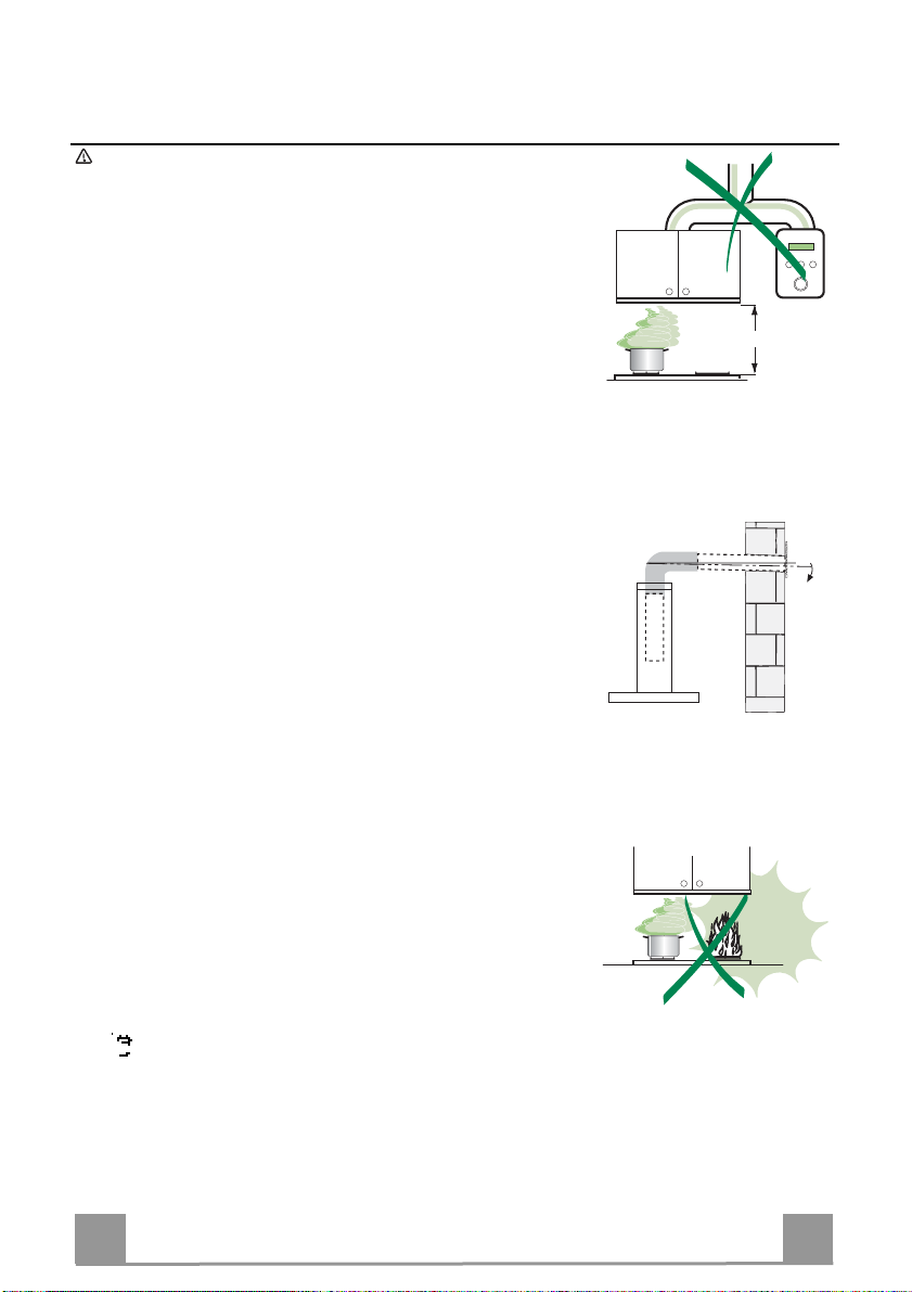
• La distanza minima di sicurezza tra il Piano di cottura e la Cappa deve essere di 650 mm, (alcuni modelli
possono essere installati ad un’altezza inferiore, fare riferimento ai paragrafi ingombro e installazione).
• Verificare che la tensione di rete corrisponda a quella riportata nella targhetta posta all’interno della Cappa.
• Per Apparecchi in Classe Iaaccertarsi che l’impianto elettrico domestico garantisca un corretto scarico a
terra.
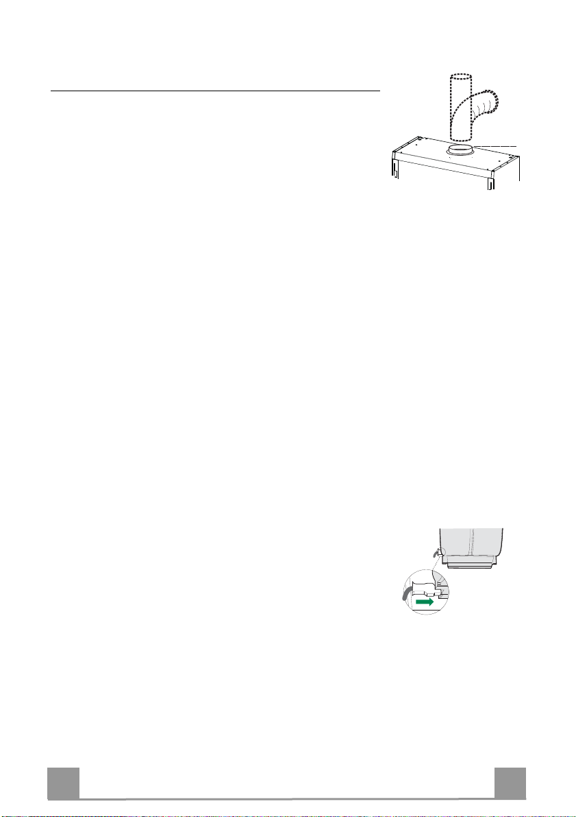
• Collegare la Cappa all’uscita dell’aria aspirata con tubazione di diametro pari o superiore a 120 mm. Il
percorso della tubazione deve essere il più breve possibile.
• Non collegare la Cappa a condotti di scarico dei fumi prodotti da combustione (caldaie, caminetti, ecc.).
• Nel caso in cui nella stanza vengano utilizzati sia la Cappa che apparecchi non azionati da energia elettrica
(ad esempio apparecchi utilizzatori di gas), si deve provvedere ad una aerazione sufficiente dell’ambiente.
Se la cucina ne fosse sprovvista, praticare un’apertura che comunichi con l’esterno, per garantire il richia-
mo d’aria pulita. Un uso proprio e senza rischi si ottiene quando la depressione massima del locale non
supera i 0,04 mBar.
• In caso di danneggiamento del cavo alimentazione, esso deve essere sostituito dal costruttore o dal servi-
zio di assistenza tecnica, in modo da prevenire ogni rischio.
• Se le istruzioni di installazione del dispositivo di cottura a gas indicano che è necessaria una distanza
maggiore di quella indicato sopra, è necessario tenerne conto. Bisogna rispettare tutte le normative relative
allo scarico dell’aria.
USO
• La Cappa è stata progettata esclusivamente per uso domestico, per abbattere gli odori della cucina.
• Non fare mai uso improprio della Cappa.
• Non lasciare fiamme libere a forte intensità sotto la Cappa in funzione.
• Regolare sempre le fiamme in modo da evitare una evidente fuoriuscita laterale delle stesse rispetto al
fondo delle pentole.
• Controllare le friggitrici durante l’uso: l’olio surriscaldato potrebbe infiammarsi.
• Non preparare alimenti flambè sotto la cappa da cucina; pericolo d'incendio.
• Questo apparecchio non deve essere utilizzato da persone (bambini inclusi) con ridotte capacità psichiche,
sensoriali o mentali, oppure da persone senza esperienza e conoscenza, a meno che non siano controllati
o istruiti all’uso dell’apparecchio da persone responsabili della loro sicurezza.
• I bambini devono essere supervisionati per assicurarsi che non giochino con l’apparecchio.
• “ATTENZIONE: Le parti accessibili possono diventare molto calde se utilizzate con degli apparecchi di
cottura.”
MANUTENZIONE
• Prima di procedere a qualsiasi operazione di manutenzione, disinserire la Cappa togliendo la spina elettri-
ca o spegnendo l’interruttore generale.
• Effettuare una scrupolosa e tempestiva manutenzione dei Filtri secondo gli intervalli consigliati (Rischio di
incendio).
• Per la pulizia delle superfici della Cappa è sufficiente utilizzare un panno umido e detersivo liquido neutro.
Il simbolo sul prodotto o sulla confezione indica che il prodotto non deve essere considerato come un normale rifiuto domestico, ma
deve essere portato nel punto di raccolta appropriato per il riciclaggio di apparecchiature elettriche ed elettroniche. Provvedendo a smaltire
questo prodotto in modo appropriato, si contribuisce a evitare potenziali conseguenze negative per l’ambiente e per la salute, che potreb-
bero derivare da uno smaltimento inadeguato del prodotto. Per informazioni più dettagliate sul riciclaggio di questo prodotto, contattare
l’ufficio comunale, il servizio locale di smaltimento rifiuti o il negozio in cui è stato acquistato il prodotto.
650 mm min.
2°

IT 6
6
CARATTERISTICHE
Ingombro
Componenti
Rif. Q.tà Componenti di Prodotto
11 Corpo Cappa completo di: Comandi, Luce, Filtri, Grup-
po Aspiratore.
91 Flangia ø120 mm
Rif. Q.tà Componenti di Installazione
7.2 2 Staffe Fissaggio Corpo Cappa
7.3 2 Squadrette di Sicurezza
11 6 Tasselli
12a 6 Viti
Q.tà Documentazione
1 Libretto Istruzioni
12a
11
9
7.3
1
7.2

IT 7
7
INSTALLAZIONE
FISSAGGIO DEL PANNELLO FRONTALE ALLA VISIERA
• Estrarre la visiera metallica ruotandola in avanti, sbloccando
contemporaneamente il fermo posto sulla sinistra della cappa.
• Forare il pannello utilizzando l’apposita dima in cartone e fis-
sarlo alla visiera con viti in dotazione.
FISSAGGIO AL MURO
• La profondità della Cappa può variare tra i 275 e 360 mm.
• Agire sulle Viti Vx per regolare le staffe alla profondità deside-
rata.
• Per regolare la parte inferiore della Cappa alla profondità ne-
cessaria, allentare le Viti del distanziale metallico e spostarlo
quanto richiesto.
• Forare la parete utilizzando l’apposita dima in cartone, applica-
re i tasselli nei fori e fissare le due staffe metalliche con quattro
viti in dotazione negli accessori.
• Forare i pensili laterali utilizzando l’apposita dima in cartone.
Nel caso di Istallazione della Cappa in Versione Aspirante, ri-
muovere la Griglia sull’uscita dell’aria.
• Agganciare la cappa alle staffe metalliche.
• Rimontare la visiera facendo attenzione ad inserire le guide
nelle proprie sedi. Regolare lo scorrimento della visiera agendo
sulle due viti.
• Agendo sulle Viti Vy si potrà allineare la Cappa in altezza ri-
spetto ai pensili vicini.
• Se necessario regolare ancora la profondità della Cappa.
• Appoggiare le Squadrette di Sicurezza sopra le Staffe di Fis-
saggio.
• Segnare il centro dei fori.
• Forare il muro e fissare le Squadrette di Sicurezza con Viti e
Tasselli in dotazione.
275-360 mm
Vx
Vy
Vx
Vy

IT 8
8
Connessioni
USCITA ARIA VERSIONE ASPIRANTE
Per installazione in Versione Aspirante collegare la Cappa alla
tubazione di uscita per mezzo di un tubo rigido o flessibile di
ø120 mm, la cui scelta è lasciata all'installatore.
• Fissare il tubo con adeguate fascette stringitubo. Il materiale
occorrente non è in dotazione.
• Togliere eventuali Filtri Antiodore al Carbone attivo.
ø 120
9
USCITA ARIA VERSIONE FILTRANTE
• Verificare che il Fissaggio del Corpo Cappa sia Completo.
• Assicurarsi della presenza dei Filtri antiodore al Carbone attivo.
CONNESSIONE ELETTRICA
• Collegare la Cappa all’Alimentazione di Rete interponendo un
Interruttore bipolare con apertura dei contatti di almeno 3 mm.
• Rimuovere i Filtri antigrasso (vedi par. “Manutenzione”) e as-
sicurarsi che il connettore del Cavo di alimentazione sia corret-
tamente inserito nella presa dell’Aspiratore

IT 9
9
USO
Quadro comandi
1Luci Accende e spegne l’Impianto di Illuminazione.
2Motore Accende e spegne il motore Aspirazione.
3Velocità Determina le velocità di esercizio:
1. Velocità minima, adatta ad un ricambio d’aria continuo particolarmente silen-
zioso, in presenza di pochi vapori di cottura.
2. Velocità media, adatta alla maggior parte delle condizioni d’uso, dato l’ottimo
rapporto tra portata d’aria trattata e livello sonoro.
3. Velocità massima, adatta a fronteggiare le massime emissioni di vapore di cot-
tura, anche per tempi prolungati.
OPZIONALI
4Micro Microinterruttore azionato dal movimento della visiera, comanda l’accensione e
lo spegnimento alle condizioni predeterminate dai cursori del quadro comandi.
5Led Segnala l’accensione del motore di Aspirazione.
1
2
3
5
4

IT 1
10
MANUTENZIONE
FILTRO ANTIGRASSO METALLICO
È necessario lavare con normale detersivo domestico questi filtri
al massimo ogni 2 mesi; la loro dimensione compatta consente il
lavaggio anche in lavastoviglie.
Smontaggio dei filtri
• Aprire la griglia di aspirazione premendo i pomelli di chiusura
verso il centro e tirando contemporaneamente verso il basso.
• Togliere i fermafiltro in filo metallico e i filtri antigrasso.
FILTRO AL CARBONE VEGETALE ATTIVO
Ha la funzione di trattenere gli odori presenti nel flusso d'aria che
lo attraversa.
L'aria viene reimmessa nell'ambiente cucina depuratasi per suc-
cessivi passaggi attraverso il filtro. Il filtro al carbone non può
essere lavato e va sostituito mediamente ogni tre mesi. Per ri-
muovere il filtro al carbone, aprire la griglia metallica di aspira-
zione e ruotare leggermente il filtro in senso antiorario con una
mano facendo nello stesso tempo una leggera pressione. Per ri-
montarlo invertire le operazioni.
ATTENZIONE! C'è un possibile rischio di incendio se i filtri
non sono puliti e sostituiti secondo le istruzioni del produtto-
re.Per rimuovere il fintro antigrasso è indispensabile aprire
la griglia di aspirazione e rimuovere gli appositi ferma filtro
in filo metallico.
Illuminazione
SOSTITUZIONE LAMPADE
Lampade da 28W-40W
• Togliere i Filtri antigrasso metallici.
• Svitare le Lampade e sostituirle con nuove di uguali caratteri-
stiche.
• Rimontare i Filtri antigrasso metallici.

EN 1
11
RECOMMENDATIONS AND SUGGESTIONS
The Instructions for Use apply to several versions of this appliance. Accordingly, you may find
descriptions of individual features that do not apply to your specific appliance.
INSTALLATION
• The manufacturer will not be held liable for any damages resulting from incorrect or improper
installation.
• The minimum safety distance between the cooker top and the extractor hood is 650 mm (some
models can be installed at a lower height, please refer to the paragraphs on working dimensions
and installation).
• Check that the mains voltage corresponds to that indicated on the rating plate fixed to the inside of
the hood.
• For Class I appliances, check that the domestic power supply guarantees adequate earthing.
Connect the extractor to the exhaust flue through a pipe of minimum diameter 120 mm. The route
of the flue must be as short as possible.
• Do not connect the extractor hood to exhaust ducts carrying combustion fumes (boilers, fireplaces,
etc.).
• If the extractor is used in conjunction with non-electrical appliances (e.g. gas burning appliances), a
sufficient degree of aeration must be guaranteed in the room in order to prevent the backflow of
exhaust gas. The kitchen must have an opening communicating directly with the open air in order
to guarantee the entry of clean air. When the cooker hood is used in conjunction with appliances
supplied with energy other than electric, the negative pressure in the room must not exceed 0,04
mbar to prevent fumes being drawn back into the room by the cooker hood.
• In the event of damage to the power cable, it must be replaced by the manufacturer or by the
technical service department, in order to prevent any risks.
• If the instructions for installation for the gas hob specify a greater distance specified above, this has
to be taken into account. Regulations concerning the discharge of air have to be fulfilled.
USE
• The extractor hood has been designed exclusively for domestic use to eliminate kitchen smells.
• Never use the hood for purposes other than for which it has been designed.
• Never leave high naked flames under the hood when it is in operation.
• Adjust the flame intensity to direct it onto the bottom of the pan only, making sure that it does not
engulf the sides.
• Deep fat fryers must be continuously monitored during use: overheated oil can burst into flames.
• Do not flambè under the range hood; risk of fire
• This appliance is not intended for use by persons (including children) with reduced physical, sen-
sory or mental capabilities, or lack of experience and knowledge, unless they have been given su-
pervision or instruction concerning use of the appliance by a person responsible for their safety.
• Children should be supervised to ensure that they do not play with the appliance.
• “ CAUTION: Accessible parts may become hot when used with cooking appliances.”.
MAINTENANCE
• Switch off or unplug the appliance from the mains supply before carrying out any maintenance
work.
• Clean and/or replace the Filters after the specified time period (Fire hazard).
• Clean the hood using a damp cloth and a neutral liquid detergent.
The symbol on the product or on its packaging indicates that this product may not be treated as household waste. Instead it shall be handed over to the
applicable collection point for the recycling of electrical and electronic equipment. By ensuring this product is disposed of correctly, you will help prevent potential negative
consequences for the environment and human health, which could otherwise be caused by inappropriate waste handling of this product. For more detailed information
about recycling of this product, please contact your local city office, your household waste disposal service or the shop where you purchased the product.
650 mm min.
2°

EN 1
12
CHARACTERISTICS
Dimensions
Components
Ref. Q.ty Product Components
11 Hood Body, complete with :Controls, Light, Blower,
Filters
9 1 Flange ø120 mm
Ref. Q.ty Installation Components
7.2 2 Hood Body Fixing Brackets
7.3 2 Safety Squares
11 6 Wall Plugs
12a 6 Screws
Q.ty Documentation
1 Instruction Manual
12a
11
9
7.3
1
7.2

EN 1
13
INSTALLATION
FIXING OF THE FRONTAL PANEL TO THE VISOR
• Pull out the metal visor and, at the same time, unlock the lever
on the left side of the hood.
• Use the cardboard template when drilling the front panel. Fix
the panel to the visor using the screws supplied.
FIXING OF THE HOOD TO THE WALL
• Hood depth can vary from 275 to 360 mm.
• Regulate the Vx screws when adjusting the brackets to the
right depth.
• When adjusting the lower part of the hood to the requested
depth it is necessary to loose the screws of the metal distance
piece and to move it as much as necessary.
• Use the specific cardboard template when drilling the holes
into the wall. Put the dowels into the holes and fix the two
metal brackets using the four screws supplied together with
other accessories.
• Use the specific cardboard template when drillig the side clos-
ets.
When the hood is used in ducting version it is necessary to re-
move the grid from the air outlet.
• Hang the hood on the metal brackets.
• Put back the visor again paying attention that the runners are
put correctly into the proper places. Adjust the visor sliding by
means of the two screws.
• Regulating the Vy screws it is possible to align the hood height
compared to the closets.
• When necessary adjust again the hood depth.
• Place the safety squares above the fixing brackets.
• Mark the midpoint of the holes.
• Drill the wall and fix the safety squares together with screws
and dowels (supplied).
275-360 mm
Vx
Vy
Vx
Vy

EN 1
14
Connections
DUCTED VERSION AIR EXHAUST SYSTEM
When installing the ducted version, connect the hood to the
chimney using either a flexible or rigid pipe ø120 mm, the choice
of which is left to the installer.
• Fix the pipe in position using sufficient pipe clamps (not sup-
plied).
• Remove any activated charcoal filters.
ø 120
9
AIR OUTLET IN RECYCLING VERSION
• Make sure that the hood body has been completely fixed.
• Make sure that hood is equipped with charcoal filters.
ELECTRICAL CONNECTION
• Connect the hood to the mains through a two-pole switch hav-
ing a contact gap of at least 3 mm.
• Remove the grease filters (see paragraph Maintenance) being
sure that the connector of the feeding cable is correctly inserted
in the socket placed on the side of the fan.

EN 1
15
USE
Control board
1Lighting On/off lighting system.
2Motor On/off motor.
3Speed Speed control:
1. Minimum speed, particularly silent, continuous air exchange, suitable in pres-
ence of only few cooking vapours and odours.
2. Medium speed, due to an optimum relation between hood extraction capacity
and the noise level, it is suitable for most of the cooking conditions.
3. Maximum speed, suitable for the cooking conditions when vapours and smells
are of the utmost emission even for a longer time.
OPTIONAL
4Microswitch Microswitch, which is activated by the movement of the visor. It switches on and
off the hood basing on the conditions which have been earlier established with
the sliders of the control panel.
5Led Led indicating when the motor is on.
1
2
3
5
4

EN 1
16
MAINTENANCE
METAL GREASE FILTERS
The metal grease filters should be cleaned every two months with
normal usage and can be cleaned in a dishwasher or by hand us-
ing a mild detergent or liquid soap.
Removal
• Open the metal grille pushing the knobs towards the centre
while pulling downwards.
• Remove the wire clips and remove the filters.
CHARCOAL FILTER
In the recycling mode the charcoal filter absorbs smells and
odours. The charcoal filter cannot be cleaned and should be re-
placed at least every six months or more frequently if the hood is
used consistently.
To replace the charcoal filter, support the filter with one hand,
remove the round disk through the centre of the charcoal filter
and rotate it till the filter will come away .
Replace by reversing the operation.
WARNING! It is a possible fire hazard if the filters are not
cleaned and replaced as recommended.
Lighting
LIGHT REPLACEMENT
28W-40W light.
• Remove the metal grease filters.
• Unscrew the bulbs and replace them with new ones having the
same characteristics.
• Replace the metal grease filters.

FR 1
17
CONSEILS ET SUGGESTIONS
La présente notice d'emploi vaut pour plusieurs versions de l'appareil. Elle peut contenir des descriptions d'ac-
cessoires ne figurant pas dans votre appareil.
INSTALLATION
• Le fabricant décline toute responsabilité en cas de dommage dû à une installation non correcte ou non
conforme aux règles de l’art.
• La distance minimale de sécurité entre le plan de cuisson et la hotte doit être de 650 mm au moins (certains
modèles peuvent être installés à une hauteur inférieure : se reporter aux paragraphes « Encombrement » et
« Installation »).
• Vérifier que la tension du secteur correspond à la valeur qui figure sur la plaquette apposée à l’intérieur de la
hotte.
• Pour les Appareils appartenant à la Ière Classe, veiller à ce que la mise à la terre de l’installation électrique
domestique ait été effectuée conformément aux normes en vigueur.
• Connecter la hotte à la sortied’air aspiré à l’aide d’une tuyauterie d’un diamètre égal ou supérieur à 120 mm. Le
parcours de la tuyauterie doit être le plus court possible.
• Ne pas connecter la hotte à des conduites d’évacuation de fumées issues d’une combustion tel que (Chau-
dière, cheminée, etc…).
• Si vous utilisez des appareils qui ne fonctionnent pas à l’électricité dans la pièce ou est installée la hotte (par
exemple: des appareils fonctionnant au gaz), vous devez prévoir une aération suffisante du milieu. Si la cuisine
en est dépourvue, pratiquez une ouverture qui communique avec l’extérieur pour garantir l’infiltration de l’air pur.
Pour un emploi correct etsans risque, la dépression maximum dansla pièce ne doit pas dépasser 0,04 mbar.
• En cas d’endommagement du cordon d’alimentation, faites-le remplacer par le constructeur ou par le service
après-vente, afin deprévenir tout risque.
• Si les instructions de montage pour la plaque de cuisson au gaz spécifient une plus grande distance indiquée ci-
dessus, cela doit être pris en compte. Règlement concernant l'évacuation d'air doivent être remplies..
UTILISATION
• La hotte a été conçue exclusivement pour l’usage domestique, dans le but d’éliminer les odeurs de la cuisine.
• Ne jamais utiliser abusivement la hotte.
• Ne pas laisser les flammes libres à forte intensité quand la hotte est enservice.
• Toujours régler les flammes de manière à éviter toute sortie latérale de ces dernières par rapport au fond des
marmites.
• Contrôler les friteuses lors de l’utilisationcar l’huile surchauffée pourrait s’enflammer.
• Ne pas préparer d’aliments flambés sous la hotte de cuisine : risque d’incendie
• Cet appareil ne doit pas être utilisé par des personnes (y compris les enfants) ayant des capacités psychiques,
sensorielles ou mentales réduites, ni par des personnesn’ayant pas l’expérience et la connaissance de ce type
d’appareils, à moinsd'être sous le contrôle et la formationde personnes responsables de leursécurité.
• Les enfants doivent être surveillés pour s'assurerqu'ils ne jouent pas avec l'appareil.
• « ATTENTION : Les parties accessibles peuvent devenir très chaudes si utilisées avec des appareils de cuis-
son. »
ENTRETIEN
• Avant de procéder à toute opération d’entretien, débrancher la hotte en retirant la fiche ou en actionnant
l’interrupteur général.
• Effectuer un entretien scrupuleux et en tempsdû des Filtres, à la cadence conseillée (Risque d’incendie).
• Pour le nettoyage des surfaces de la hotte, il suffit d’utiliser un chiffon humide et détersif liquide neutre.
Le symbole sur le produit ou son emballage indique que ce produit ne peut être traité comme déchet
ménager. Il doit plutôt être remis au point de ramassage concerné, se chargeant du recyclage du matériel
électrique et électronique. En vous assurant que ce produit est éliminé correctement, vous favorisez la pré-
vention des conséquences négatives pour l’environnement et la santé humaine qui, sinon, seraient le résultat
d’un traitement inapproprié des déchets de ce produit. Pour obtenir plus de détails sur le recyclage de ce
produit, veuillez prendre contact avec le bureau municipal de votre région, votre service d’élimination des
déchets ménagers ou le magasin où vous avez acheté le produit.
650 mm min.
2°

FR 1
18
CARACTERISTIQUES
Encombrement
Composants
Réf. Q.té Composants de Produit
11 Corps Hotte équipé de: Comandes, Lumière, Groupe
Ventilateur, Filtres
91 Flasque ø120 mm
Réf. Q.té Composants pour l ’installation
7.2 2 Brides Fixation Corps Hotte
7.3 2 équerre de sûreté
11 6 Chevilles
12a 6 Vis
Q.té Documentation
1 Manuel d’instructions
12a
11
9
7.3
1
7.2

FR 1
19
INSTALLATION
FIXATION DU PANNEAU FRONTAL SUR LA VISIERE
• Sortir la visière métallique en la tournant en avant et en déblo-
quant en même temps le dispositif d’arrêt qui se trouve à gau-
che de la hotte.
• Percer le panneau en utilisant le gabarit en carton spécialement
prévu, puis fixer ledit panneau contre la visière à l’aide des vis
fournies avec l’appareil.
FIXATION CONTRE LA PAROI
• La profondeur de la Hotte peut varier entre 275 et 360 mm.
• Intervenir sur les Vis Vx pour régler les brides à la profondeur
souhaitée.
• Pour régler la partie inférieure de la Hotte à la profondeur né-
cessaire, desserrer les Vis de l’entretoise métallique et dépla-
cer cette dernière dans la mesure requise.
• Percer la paroi en utilisant le gabarit en carton spécialement
prévu, appliquer les chevilles dans les trous et fixer les deux
brides métalliques à l’aide de quatre vis, fournies avec les ac-
cessoires.
• Percer les armoires murales latérales, en utilisant le gabarit en
carton spécialement prévu.
En cas d’installation de la Hotte dans la Version Aspirante, retirer
la Grille sur la sortie d’évacuation de l’air.
• Accrocher la hotte aux les brides métalliques.
• Remonter la visière en veillant à ce que les guides soient insé-
rées dans leurs logements. Régler le coulissement de la visière
en intervenant sur les deux vis.
• On peut effectuer l’alignement de la hauteur de la Hotte par
rapport aux armoires murales qui se trouvent à côté de celle-ci,
en intervenant sur les Vis Vy.
• Régler encore la profondeur de la Hotte, si nécessaire.
• Poser les Équerres de Sécurité sur les Brides de Fixation.
• Marquer le centre des trous.
• Percer le mur et fixer les Équerres de Sécurité avec les Vis et
les Chevilles fournies avec l’appareil.
275-360 mm
Vx
Vy
Vx
Vy

FR 2
20
Branchements
SORTIE AIR VERSION EVACUATION
En cas d’installation en version évacuation, brancher la hotte à la
tuyauterie de sortie via un tube rigide ou flexible de ø 120 mm,
au choix de l’installateur.
• Fixer le tube par des colliers appropriés. Le matériau néces-
saire n’est pas fourni.
• Retirer les éventuels filtres anti-odeur au charbon actif.
ø 120
9
SORTIE D’EVACUATION DE L’AIR DANS LA VERSION FILTRANTE
• Contrôler que la Fixation du Corps de la Hotte soit Complète.
• S’assurer que les Filtres anti-odeur au Charbon actif soient présents.
BRANCHEMENT ELECTRIQUE
• Brancher la hotte sur le secteur en interposant un interrupteur
bipolaire avec ouverture des contacts d’au moins 3 mm.
• Enlever les filtres à graisse (voir § "Entretien") et s'assurer que
le connecteur du câble d'alimentation soit bien branché dans la
prise du diffuseur.
Table of contents
Languages:
Other Smeg Ventilation Hood manuals
Popular Ventilation Hood manuals by other brands

Electrolux
Electrolux Icon E368WV60ES Specification sheet

Respekta
Respekta CH 44060 BSA+ Installation & Operation Insruction

Beko
Beko HNT61630X user manual

Franke
Franke FCR 925 I TC BK XS Instructions for use and installation

Teka
Teka DV-80 GLASS instruction manual

THERMEx
THERMEx Decor 825 User instructions

ELICA
ELICA EVL430S1 Use, care and installation guide

KitchenAid
KitchenAid KWCU300L Dimension Guide

Siemens
Siemens LR18HLT25 User manual and installation instructions

Mistral
Mistral LAZS430SB Installation guide and user's manual

Electrolux
Electrolux EFP 60310 user manual

Vortice
Vortice VORTEX 60-I Instruction booklet/Installation Manual