Smeg KSEU912X User manual

Manuel d’Instructions
Instructions Manual
Manual de instrucciones
LibrettoIstruzioni
KSEU912X

EN 2
2
INDEX
WARNINGS AND REQUIREMENTS .................................................................................................................................... 3
RECOMMENDATIONS AND SUGGESTIONS.....................................................................................................................6
DIMENSIONS and MAIN PARTS..........................................................................................................................................7
INSTALLATION...................................................................................................................................................................... 8
USE......................................................................................................................................................................................11
CARE ...................................................................................................................................................................................12

EN 3
3
READ AND SAVE THESE INSTRUCTIONS
The Installer must leave these instructions with the homeowner.
The homeowner must keep these instructions for future reference and for local electrical inspec-
tors’ use.
READ THESE INSTRUCTIONS BEFORE YOU START INSTALLING THIS RANGEHOOD
WARNING: - TO REDUCE THE RISK OF A RANGE TOP GREASE FIRE: Never leave surface units
unattended at high settings. Boilovers cause smoking and greasy spillovers that may ignite. Heat oils slowly
on low or medium setting. Always turn hood ON when cooking at high heat or when flambéing food (i.e.
Crepes Suzette, Cherries Jubilee, Peppercorn Beef Flambé). Clean ventilating fans frequently. Grease should
not be allowed to accumulate on fan or filter. Use proper pan size. Always use cookware appropriate for the
size of the surface element.
WARNING: - TO REDUCE THE RISK OF INJURY TO PERSONS IN THE EVENT OF A RANGE
TOP GREASE FIRE, OBSERVE THE FOLLOWING: SMOTHER FLAMES with a close-fitting
lid, cookie sheet, or metal tray, then turn off the burner. BE CAREFUL TO PREVENT BURNS.If
the flames do not go out immediately EVACUATE AND CALL THE FIRE DEPARTMENT. NEV-
ER PICK UP A FLAMING PAN - You may be burned.DO NOT USE WATER, including wet dish-
cloths or towels - a violent steam explosion will result. Use an extinguisher ONLY if: 1. You
know you have a Class ABC extinguisher, and you already know how to operate it. 2. The fire is
small and contained in the area where it started. 3. The fire department is being called. 4. You
can fight the fire with your back to an exit.
ALL WALL AND FLOOR OPENINGS WHERE THE RANGEHOOD IS INSTALLED MUST BE
SEALED.
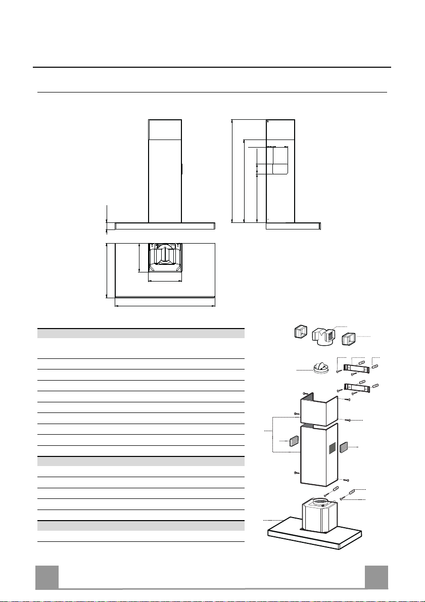
This rangehood requires at least 24" of clearance between the bottom of the rangehood and the
cooking surface or countertop. Consult the cooktop or range installation instructions given by the
manufacturer before making any cutouts. MOBILE HOME INSTALLATION. The installation
of this rangehood must conform to the Manufactured Home Construction and Safety Standards,
Title 24 CFR, Part 3280 (formerly Federal Standard for Mobile Home Construction and Safety,
Title 24, HUD, Part 280). Four wire power supply must be used and the appliance wiring must be
revised. See Electrical Requirements.
VENTING REQUIREMENTS
CAUTION - To reduce risk of fire and to properly exhaust air, be sure to duct air outside – Do not vent ex-
haust air into spaces within walls or ceilings or into attics, crawl spaces, or garages".
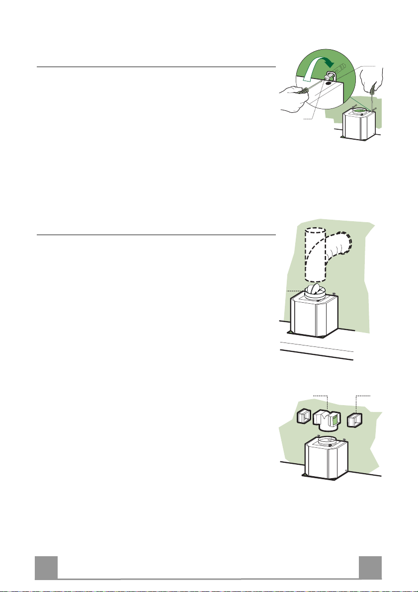
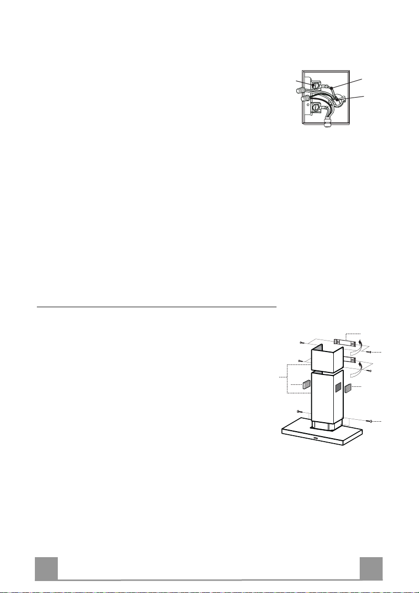
Check which venting method is best for your application. Ductwork can extend either through
the wall or the roof. The length of the ductwork and the number of elbows should be kept to a
minimum to provide efficient performance. The size of the ductwork should be constant. Do not
install two elbows together. Use duct tape to seal all joints in the ductwork system. Use caulking
to seal exterior wall or floor opening around the cap.
Flexible ductwork is not recommended. Flexible ductwork creates back pressure and air turbu-
lence that greatly reduces performance.
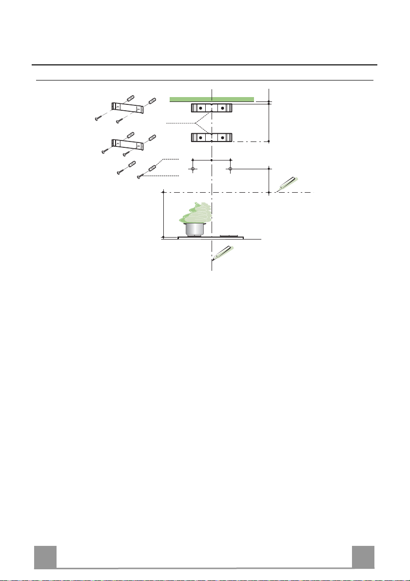
Make sure there is proper clearance within the wall or floor for exhaust duct before making cutouts.
Do not cut a joist or stud unless absolutely necessary. If a joist or stud must be cut, then a supporting
frame must be constructed.
WARNING - To Reduce The Risk Of Fire, Use Only Metal Ductwork.

EN 4
4
W A R N I N G
• Venting system MUST lead the air outside the building.
• DO NOT expel the air through a ductwork in an attic or other enclosed space.
• DO NOT use 4" laundry-type wall caps.
• Flexible-type ductwork is NOT recommended.
• DO NOT obstruct the flow of combustion and ventilation air.
• Failure to follow venting requirements may result in a fire.
ELECTRICAL REQUIREMENTS
A 120 volt, 60 Hz AC-only electrical supply is required on a separate 15 amp fused circuit. A
timedelay fuse or circuit breaker is recommended. The fuse must be sized per local codes in ac-
cordance with the electrical rating of this unit as specified on the serial/rating plate located inside
the unit near the field wiring compartment. THIS UNIT MUST BE CONNECTED WITH COP-
PER WIRE ONLY. Wire sizes must conform to the requirements of the National Electrical
Code, ANSI/NFPA 70 - latest edition, and all local codes and ordinances. Wire size and connec-
tions must conform with the rating of the appliance. Copies of the standard listed above may be
obtained from:
National Fire Protection Association
Batterymarch Park
Quincy, Massachusetts 02269
This appliance should be connected directly to the fused disconnect (or circuit breaker) through
flexible, armored or nonmetallic sheathed copper cable. Allow some slack in the cable so the ap-
pliance can be moved if servicing is ever necessary. A UL Listed, 1/2" conduit connector must
be provided at each end of the power supply cable (at the appliance and at the junction box).
When making the electrical connection, cut a 1 1/4" hole in the wall. A hole cut through wood
must be sanded until smooth. A hole through metal must have a grommet.
WARNING - TO REDUCE THE RISK OF FIRE OR ELECTRIC SHOCK, do not use this fan with
any solid-state speed control device.
WARNING - TO REDUCE THE RISK OF FIRE, ELECTRICAL SHOCK, OR INJURY TO
PERSONS, OBSERVE THE FOLLOWING: Use this unit only for the purpose intended by the manu-
facturer. If you have any questions, contact the manufacturer.
Before servicing or cleaning the unit, switch power off at service panel and lock the service dis-
connecting means to prevent power from being switched on accidentally. When the service dis-
connecting means cannot be locked, securely fasten a prominent warning device, such as a tag, to
the service panel.
CAUTION: For General Ventilating Use Only. Do Not Use To Exhaust Hazardous or Explosive Materials
and Vapors.

EN 5
5
WARNING - TO REDUCE THE RISK OF FIRE, ELECTRICAL SHOCK, OR INJURY TO
PERSONS, OBSERVE THE FOLLOWING: Installation Work And Electrical Wiring Must Be
Done By Qualified Person(s) In Accordance With All Applicable Codes And Standards, In-
cluding Fire-Rated Construction.
Sufficient air is needed for proper combustion and exhausting of gases through the flue
(chimney) of fuel burning equipment to prevent backdrafting. Follow the heating equipment
manufacturer’s guideline and safety standards such as those published by the National Fire
Protection Association (NFPA), and the American Society for Heating, Refrigeration and Air
Conditioning Engineers (ASHRAE), and the local code authorities.
When cutting or drilling into wall or ceiling, do not damage electrical wiring and other hidden
utilities.
Ducted fans must always be vented to the outdoors.
W A R N I N G
• Electrical ground is required on this rangehood.
• If cold water pipe is interrupted by plastic, nonmetallic gaskets or other materials, DO
NOT use for grounding.
• DO NOT ground to a gas pipe.
• DO NOT have a fuse in the neutral or grounding circuit. A fuse in the neutral or ground-
ing circuit could result in electrical shock
• Check with a qualified electrician if you are in doubt as to whether the rangehood is
properly grounded.
• Failure to follow electrical requirements may result in a fire.

EN 6
6
RECOMMENDATIONS AND SUGGESTIONS
The Instructions for Use apply to several versions of this appliance. According-
ly, you may find descriptions of individual features that do not apply to your
specific appliance.
INSTALLATION
• The manufacturer will not be held liable for any damages resulting from incor-
rect or improper installation.
• Check that the main voltage corresponds to that indicated on the rating plate
fixed to the inside of the hood.
• The electrical supply must be properly and sufficiently grounded.
Connect the extractor to the exhaust flue through a pipe of minimum diameter
6”. The route of the flue must be as short as possible.
• Do not connect the extractor hood to exhaust ducts carrying combustion fumes
(boilers, fireplaces, etc.).
• If the extractor is used in conjunction with non-electrical appliances (e.g. gas
burning appliances), a sufficient degree of aeration must be guaranteed in the
room in order to prevent the backflow of exhaust gas. The kitchen must have
an opening communicating directly with the open air in order to guarantee the
entry of clean air.
USE
• The range hood has been designed exclusively for domestic use to eliminate
kitchen odors.
• Never use the hood for purposes other than for which it has ben designed.
• Never leave high naked flames under the hood when it is in operation.
• Adjust the flame intensity to direct it onto the bottom of the pan only, making
sure that it does not engulf the sides.
• Deep fat fryers must be continuously monitored during use: overheated oil can
burst into flames.
• The hood should not be used by children or persons not instructed in its cor-
rect use.
CARE
• Switch off or unplug the appliance from the main supply before carrying out
any maintenance work.
• Clean and/or replace the Filters after the specified time period.
• Clean the hood using a damp cloth and a neutral liquid detergent..
THERMAL PROTECTOR
The range hood is equipped with a thermal protector to avoid overheating condi-
tions. If the range hood shuts offin use, press the on/off button to return off range
hood. Wait approximately 90 minutes, then press the on/off button to restart the
range hood.

EN 7
7
DIMENSIONS and MAIN PARTS
Dimensions
Components
Ref. Q.ty Product Components
11 Hood Body, complete with: Controls, Light, Blower,
Filters
21 Telescopic Chimney comprising:
2.1 1 Upper Section
2.2 1 Lower Section
8a 1 Right Air Outlet Grill Aria
8b 1 Left Air Outlet Grill Aria
10 1 Damper
14.1 2 Air Outlet Connection Extension
15 1 Air Outlet Connection
Ref. Q.ty Installation Components
7.2.1 2 Upper Chimney Section Fixing Brackets
11 6 Wall Plugs (if supplied)
12a 6 Screws 3/16” x 1” 3/4
12c 6 Screws 1/8” x 3/8”
Q.ty Documentation
1 Instruction Manual
5" 1/8
2" 7/16
35" 3/8
12"
3" 1/2
12" 1/2
21" 1/4
2" 3/8
10" 5/8
19" 5/16
Min. 35" - Max.38" 1/8
11
12a
1
2.1
2.2
2
12c
12a 7.2.1 11
14.1
15
8a
8b
10

EN 8
8
INSTALLATION Wall drilling and bracket fixing
Wall marking:
• Draw a vertical line on the supporting wall up to the ceiling, or as high as practical, at the
center of the area in which the hood will be installed.
• Draw a horizontal line at 24” above the hob.
• Place bracket 7.2.1 on the wall as shown about 1/16” from the ceiling or upper limit aligning
the center (notch) with the vertical reference line.
• Mark the wall at the centers of the holes in the bracket.
• Place bracket 7.2.1 on the wall as shown at X” below the first bracket (X = height of the up-
per chimney section supplied), aligning the center (notch) with the vertical line.
• Mark the wall at the centers of the holes in the bracket.
• Mark a reference point as indicated at 4” 9/16 from the vertical reference line and 13” 3/8
above the horizontal reference line.
• Repeat this operation on the other side.
• Drill ø 5/16” holes at all the center points marked.
• Insert the wall plugs 11 in the holes.
• Fix the brackets using the 12a screws supplied.
• Insert the two screws 12a supplied in the hood body fixing holes, leaving a gap of 3/16 ”
between the wall and the head of the screw.
11
12a
12"5/8 X
÷1/16"
4"9/16
24"
7.2.1
4"9/16

EN 9
9
Mounting the hood body
• Before attaching the hood body, tighten the two screws Vr lo-
cated on the hood body mounting points.
• Hook the hood body onto the screws 12a.
• Fully tighten support screws 12a.
• Adjust screws Vr to level the hood body.
Note: The Hood body should be secured to wall studs. If neces-
sary, install a wood support behind the dry wall, flush mounted
between 2 studs. This will provide the necessary structure and
support for mounting.
Connections
DUCTED VERSION AIR EXHAUST SYSTEM
When installing the ducted version, connect the hood to the
chimney using a rigid 6” duct.
• Install the damper 10 ø 6”.
• Fix the duct in position using sufficient pipe clamps (not sup-
plied).
DUCTLESS VERSION AIR OUTLET
• Push fit connection 15 onto the hood body outlet.
• Insert the connection extension pieces laterally 14.1 in connec-
tion 15.
• Make sure that the outlet of the extension pieces 14.1 is hori-
zontally and vertically aligned with the chimney outlets. If this
is not the case, adjust the position by either reversing the con-
nection extension pieces 14.1 and then reassemble as described
previously.
• Ensure that the activated charcoal filters have been inserted.
12a
Vr
10
14.115

EN 1
10
ELECTRICAL CONNECTION
• Remove the cover from the Field Wiring Compartment with a
phillips screwdriver.
• Feed the Power Supply Cable through the electrical knockout.
Connect the Power Supply Cable to the range- hood cable. At-
tach the Power Supply Cable grounding lead to the green screw
provided. Attach the White lead of the power supply to the
White lead of the rangehood with a twist-on type wire con-
nector. Attach the Black lead of the power supply to the Black
lead of the rangehood with a twist-on type wire connector.
• Replace the cover.
Chimney assembly
Upper exhaust chimney
• Slightly widen the two sides of the upper flue and hook them
behind the brackets 7.2.1, making sure that they are well seat-
ed.
• Secure the sides to the brackets using the 4 screws 12c sup-
plied.
Lower exhaust chimney
• Slightly widen the two sides of the flue and hook them be-
tween the upper flue and the wall, making sure that they are
well seated.
• Fix the lower part laterally to the hood body using the 2 screws
12c supplied.
• On the recirculation version, fit the directional grids 8a – 8b in
their housings making sure that the directional symbols are to-
wards the top and front of the hood. Also make sure that they
are correctly inserted in the connection extension pieces 14.1.
12c
8a
2.1
2.2
2
8b
7.2.1
12c
Power supply cable
Green
Ground
screw
Ground wire

EN 1
11
USE
Control board
Key Function Display
A Switches the motor on/off at the latest selected speed Indicates the selected speed
B Decreases the suction speed. -
C Increases the suction speed. -
D By pressing this key it is possible to start the intensive
speed from any previously selected speed. This speed
has been timed at 6 minutes. After that time the system
activates automatically the latest selected speed. This
function is recommended for cooking condition where
vapours and odours need to be eliminated immediately
and quickly.
HI and the remaining time appear alternately.
By pressing this key for about 5 seconds , with all the
loads turned off (Motor and Lights), it is possible acti-
vated or deactivated the Charcoal Filter alarm.
Show “FC” + (2 Flashes of a dot) – activated
Show “FC” + (1 Flashes of a dot) – deactivated
E By pressing this key it is possible to set up the motor to
a suction speed at 100 m3/h. During the intensive speed
or the Delay-function this function cannot be activated.
24 appears and the spot down at the right side flash-
es once a second.
By pressing the key the function is stopped.
F By pressing this key it is possible to set the delayed
shutdown of the hood to 30 minutes. This function is
suitable for a complete elimination of residual cooking
odours. Functioning only when the motor is on(not
during the 24H-function or intensive function)
The suction speed and a dot flash once a second.
By pressing the key the function is stopped
Pressing and holding the button for 5 seconds enables
the remote control.
Pressing and holding the button for 5 seconds disables
the remote control
Show “IR” + (2 Flashes of a dot) – activated
Show “IR” + (1 Flashes of a dot) – deactivated
G By pressing this key for about 3 seconds it is possible to
reset the filter saturation alarm. Flash “FF” three times.
After 100 working hours a FG appears. Metal grease
filters have to be washed.
After 200 working hours FC appears. Charcoal
filters have to replaced.
H By pressing this key the intensity of the lighting system
can be decreased.
I Switches on/off the lighting system at the maximum
intensity.
L By pressing this key the intensity of the lighting system
can be increases.
Keyboard lock: it is possible to jam the keyboard when, for example, cleaning the glass. The motor and lights are
switched off. By pressing for about 5 seconds the A-key the keyboard block can be activated and “00” flash once or deac-
tivated “00” flash Twice. This function is confirmed by moving motor LEDS on display.

EN 1
12
CARE
Metal grease filters
Filters can be washed in the dishwasher. They need to be washed
when FG-sign appears on the display or in any case every 2
months, or even more frequently in case of particularly intensive
use of the hood.
Alarm reset
• Press the G-key for at least 3 seconds (See Use Paragraph).
Cleaning
• Remove the filters one at a time, supporting them with one
hand and turning the safety knobs (pull and turn).
• Wash the filters. Pay attention not to bend them. Make sure
that filters are completely dry before putting them into their
seat.
• Place the filters again into their seats and make sure that the
handle of the filter remains outside.

14
EN 1
13
Charcoal filter (ductless version)
This filter cannot be washed or regenerated. It has to be replaced when the FC appears on the
display or at least once every 4 months.
Activation of the alarm signal
• In the recycling version hoods the filter saturation alarm has to be activated during the in-
stallation or later.
• Switch off the hood and the lights.
• Press the D-key within 5 seconds until a confirmation of the activated state of filter satura-
tion alarm on the display appears:
• a dot flash twice and show FC - charcoal filter saturation alarm ACTIVATED
• a dot flash once and show FC - charcoal filter saturation alarm DEACTIVATED
SUBSTITUTION OF THE CHARCOAL FILTER
Alarm reset
• Switch off the motor and the lighting system.
• Press the G-key for at least 3 seconds (See Use Paragraph).
Substitution of the filter
• Remove the metal grease filters.
• Remove the charcoal filter as indicated in the picture.
• Place the filter again into its seat.
• Place again the metal grease filters into their place.
Lighting
Warning: This appliance is fitted with a white LED lamp classed
as 1M according to EN 60825-1: 1994 + A1:2002 + A2:2001
standards; maxi-mum optical power emitted @439nm: 7µW. Do
not look directly at the light through optical devices (binoculars,
magnifying glasses…).
For replacement contact technical support. ("To purchase contact
technical support")
Table of contents
Other Smeg Ventilation Hood manuals

Smeg
Smeg KSEIR62NE2 User manual

Smeg
Smeg KT61XE User manual

Smeg
Smeg KSEG7XE User manual

Smeg
Smeg KD917X Technical manual

Smeg
Smeg KSET65 Technical manual

Smeg
Smeg SA550X90 User manual

Smeg
Smeg PUM601X Operator's manual

Smeg
Smeg KDD90CNE User manual

Smeg
Smeg K7088D150 User manual

Smeg
Smeg KI90C Technical manual
Popular Ventilation Hood manuals by other brands

Wolf
Wolf 811504 installation guide

Kitchenware
Kitchenware RIV3CL9G Installation and operating instructions

Robam
Robam CXW-200-A606 Operation manual

Windster
Windster WINT024 Installation guide and user's manual

Caple
Caple Zi900SS Instruction on mounting and use

Gaggenau
Gaggenau AH 900 Operating and installation instructions