Smeg SHW930X User manual

Instructions Manual
SHW930X

2
2
INDEX
RECOMMENDATIONS AND SUGGESTIONS..................................................................................................................... 3
CHARACTERISTICS.............................................................................................................................................................4
INSTALLATION...................................................................................................................................................................... 5
USE........................................................................................................................................................................................8
MAINTENANCE.....................................................................................................................................................................9
EN

EN 3
3
RECOMMENDATIONS AND SUGGESTIONS
The Instructions for Use apply to several versions of this appliance. Accordingly, you may find
descriptionsofindividualfeaturesthatdonotapplytoyourspecificappliance.
INSTALLATION
• The manufacturer will not be held liable for any damages resulting from incorrect or improper
installation.
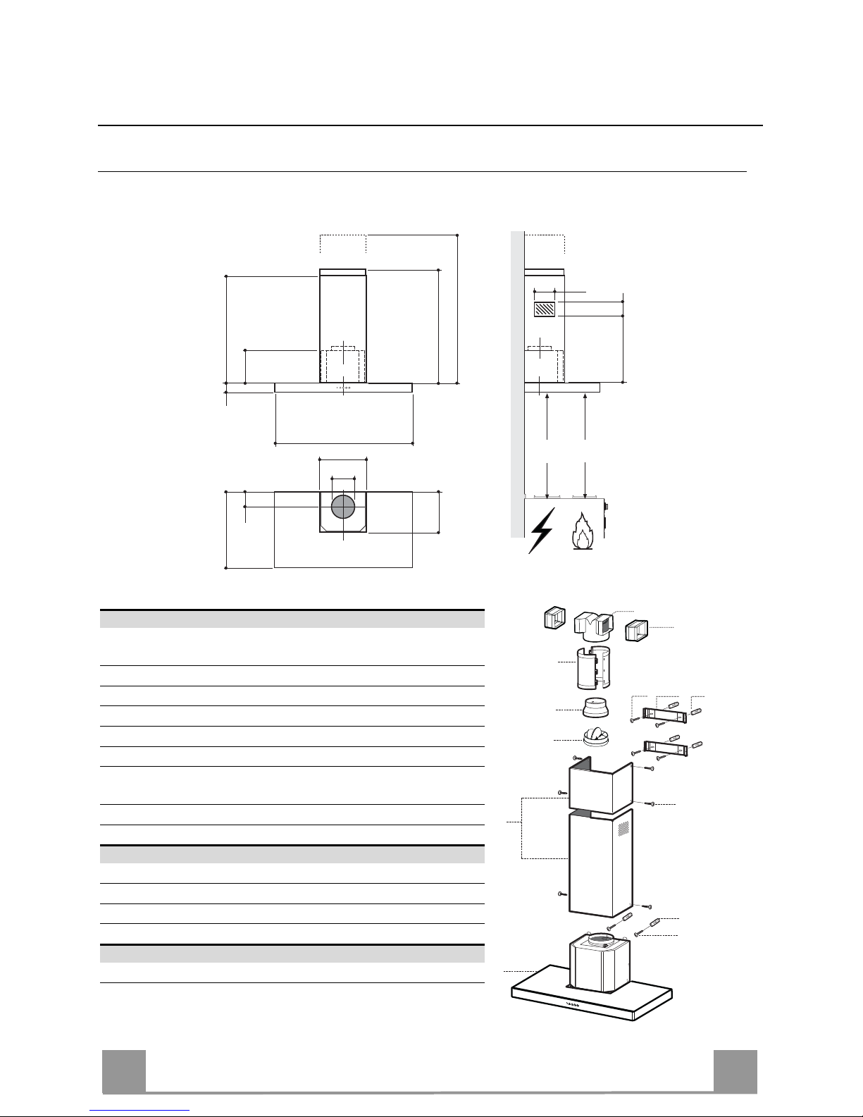
• The minimum safety distance between the cooker top and the extractor hood is 650 mm (some
models can be installed at a lower height, please refer to the paragraphs on working dimensions
andinstallation).
• Checkthatthemains voltagecorrespondstothatindicatedontheratingplatefixedtotheinside of
thehood.
• ForClassIappliances,checkthatthedomesticpowersupplyguaranteesadequateearthing.
Connecttheextractortotheexhaust fluethrougha pipe of minimumdiameter120mm.The route
ofthefluemustbeasshortaspossible.
• Donotconnecttheextractorhoodtoexhaustductscarryingcombustionfumes(boilers,fireplaces,
etc.).
• Iftheextractorisusedinconjunctionwithnon-electricalappliances(e.g.gasburningappliances),a
sufficient degree of aeration must be guaranteed in the room in order to prevent the backflow of
exhaust gas.Thekitchenmust havean opening communicatingdirectly withthe openairinorder
to guarantee the entry of clean air. When the cooker hood is used in conjunction with appliances
supplied with energy other than electric, the negative pressure in the room must not exceed 0,04
mbartopreventfumesbeingdrawnbackintotheroombythecookerhood.
• In the event of damage to the power cable, it must be replaced by the manufacturer or by the
technicalservicedepartment,inordertopreventanyrisks.
“WARNING:Failuretoinstallthescrewsorfixingdeviceinaccordancewiththeseinstructionsmay
resultinelectricalhazards.”
USE
• Theextractorhoodhasbeendesignedexclusivelyfordomesticusetoeliminatekitchensmells.
• Neverusethehoodforpurposesotherthanforwhichithasbeendesigned.
• Neverleavehighnakedflamesunderthehoodwhenitisinoperation.
• Adjust the flame intensity to direct it onto the bottom of the pan only, making sure that it does not
engulfthesides.
• Deepfatfryersmustbecontinuouslymonitoredduringuse:overheatedoilcanburstintoflames.
• Donotflambèundertherangehood;riskoffire
• This appliance is not intended for use by persons (including children) with reduced physical, sen-
soryormentalcapabilities,orlackofexperienceandknowledge,unlesstheyhavebeen givensu-
pervisionorinstructionconcerninguseoftheappliancebyapersonresponsiblefortheirsafety.
• Childrenshouldbesupervisedtoensurethattheydonotplaywiththeappliance.
• “WARNING:Accessiblepartsmaybecomehotwhenusedwithcookingappliances.”.
MAINTENANCE
• Switch off or unplug the appliance from the mains supply before carrying out any maintenance
work.
• Cleanand/orreplacetheFiltersafterthespecifiedtimeperiod(Firehazard).
• Cleanthehoodusingadampclothandaneutralliquiddetergent.
Thesymbol on theproduct or on its packaging indicates that this product may not be treatedas household waste. Instead it
shallbehandedovertotheapplicablecollectionpointfortherecyclingofelectricalandelectronicequipment.Byensuringthisproduct
is disposed of correctly, you willhelpprevent potentialnegative consequencesfor the environment and humanhealth, which could
otherwise be caused by inappropriate waste handling of this product. For more detailed information about recycling of this product,
pleasecontactyourlocalcityoffice,yourhouseholdwastedisposalserviceortheshopwhereyoupurchasedtheproduct.
2°

EN 4
4
CHARACTERISTICS
Dimensions
84
126
314
490 80
108 259
150
min. 890
max. 1100
740
260
300
898
Min.
650mm
Min.
650mm
Components
Ref. Q.ty Product Components
11 Hood Body, complete with: Controls, Light, Blower,
Filters
21 Telescopic Chimney comprising:
2.1 1 Upper Section
2.2 1 Lower Section
91 Reducer Flange ø 150-120 mm
10 1 Damper
14 1 Hood Body Air Outlet Extension Piece consisting of two
Half Shells
14.1 2 Air Outlet Connection Extension
15 1 Air Outlet Connection
Ref. Q.ty Installation Components
7.2.1 2 Upper Chimney Section Fixing Brackets
11 6 Wall Plugs
12a 6 Screws 4,2 x 44,4
12c 6 Screws 2,9 x 9,5
Q.ty Documentation
1 Instruction Manual
2.1
2.2
2
12c
12a 7.2.1 11
11
12a
1
9
10
14.1
15
14

EN 5
5
INSTALLATION Wall drilling and bracket fixing
Wall marking:
• Draw a vertical line on the supporting wall up to the ceiling, or as high as practical, at the
centre of the area in which the hood will be installed.
• Draw a horizontal line at 650 mm above the hob. Place bracket 7.2.1 on the wall as shown
about 1-2 mm from the ceiling or upper limit aligning the centre (notch) with the vertical
reference line.
• Mark the wall at the centres of the holes in the bracket.
• Place bracket 7.2.1 on the wall as shown at X mm below the first bracket (X = height of the
upper chimney section supplied), aligning the centre (notch) with the vertical line.
• Mark the wall at the centres of the holes in the bracket.
• Mark a reference point as indicated at 116 mm from the vertical reference line and 340 mm
above the horizontal reference line.
• Repeat this operation on the other side.
• Drill ø 8 mm holes at all the centre points marked.
• Insert the wall plugs 11 in the holes.
• Fix the brackets using the 12a (4,2 x 44,4) screws supplied.
• Insert the two screws 12a (4,2 x 44,4) supplied in the hood body fixing holes, leaving a gap
of 5-6 mm between the wall and the head of the screw.
11
12a
340 X
116
1÷2
116
650 min.
7.2.1

EN 6
6
Mounting the hood body
• Before attaching the hood body, tighten the two screws Vr lo-
cated on the hood body mounting points.
• Hook the hood body onto the screws 12a.
• Fully tighten the support screws 12a.
• Adjust the screws Vr to level the hood body.
12a
Vr
Connections
DUCTED VERSION AIR EXHAUST SYSTEM
When installing the ducted version, connect the hood to the
chimney using either a flexible or rigid pipe ø 150 or 120mm, the
choice of which is left to the installer.
To install a ø 150 pipe
• To install the dumper 10
• Fix the pipe in position using sufficient pipe clamps (not sup-
plied).
To install a ø 120 pipe
• To install a ø 120 mm air exhaust connection, insert the re-
ducer flange 9on the dumper 10.
• Fix the pipe in position using sufficient pipe clamps (not sup-
plied).
• Remove any activated charcoal filters.
9
ø 120ø 150
10
10
RECIRCULATION VERSION AIR OUTLET
• Assemble the two halves of the hood body extension piece 14
• Push fit the assembled hood body extension piece 14 onto the
air outlet.
• Push fit connection 15 onto the hood body extension piece 14.
• Insert the connection extension pieces laterally 14.1 in connec-
tion 15.
• Make sure that the outlet of the extension pieces 14.1 is hori-
zontally and vertically aligned with the chimney outlets.
If this is not the case, adjust the position by either reversing the
connection extension pieces 14.1 or by cutting the hood body
extension 14 along one of the thinner section channels denot-
ing the prefixed lengths, then reassemble as described previ-
ously.
• Ensure that the activated charcoal filters have been inserted.
14.115
14

EN 7
7
ELECTRICAL CONNECTION
• Connect the hood to the mains through a two-pole switch hav-
ing a contact gap of at least 3 mm.
• Remove the grease filters (see paragraph Maintenance) being
sure that the connector of the feeding cable is correctly inserted
in the socket placed on the side of the fan.
Chimney assembly
Upper exhaust Chimney
• Slightly widen the two sides of the upper chimney and hook
them behind the brackets 7.2.1, making sure that they are well
seated.
• Secure the sides to the brackets using the 4 screws 12c (2,9 x
9,5) supplied.
Lower exhaust Chimney
• Slightly widen the two sides of the chimney and hook them
between the upper chimney and the wall, making sure that they
are well seated.
• Fix the lower part laterally to the hood body using the 2 screws
12c (2,9 x 9,5) supplied.
12c
2.1
2.2
2
7.2.1
12c

EN 8
8
USE
L T1 T2 T3 T4
L1 L2 L3 L4
Control panel
Button Function Led
LPress briefly to turn the lighting system on and off.
Press and hold for approx. 2 seconds to turn the lighting system
on and off at reduced intensity.
-
T1 Turn the suction motor on and off at speed one.
If the filter saturation alarm is on, this resets it. On.
T2 Turn the suction motor on at speed two.
If the filter saturation alarm is on, this resets it. On.
T3 Press once to turn the suction motor on and off at speed three.
Press again to activate intensive speed. This speed is timed to run
for 10 minutes. At the end of this time the system will
automatically return to the speed set before.
Suitable to deal with maximum levels of cooking fumes, it is de-
activated by pressing any one of the Speed buttons (T1-T2-T3).
It cannot be activated if the Delay function is in use.
If the filter saturation alarm is on, this resets it.
On.
Flashing.
T4 Activate automatic switch-off with a 30’ delay (Motor+Lights).
Suitable to complete elimination of residual odours.
Can be activated from any Speed, and is disabled by pressing the
button again or turning the motor off.
It cannot be activated if the Intensive function is in use.
If the filter saturation alarm is on, this resets it.
On.
Warning: The working hours of the motor are counted for the purpose of signalling filter
saturation.
After 100 working hours all the LEDs (L1-L2-L3-L4) will light up and remain lit to indicate
saturation of the metal grease filters.
After 200 working hours all the LEDs (L1-L2-L3-L4) will light up and start to flash to indicate
saturation of the activated charcoal filters.

EN 9
9
MAINTENANCE
Cleaning the Comfort Panels
• Pull the Comfort Panel to open it.
• Disconnect the panel from the hood canopy by sliding the fix-
ing pin lever.
• The comfort panel must never be washed in a dishwasher.
• Clean the outside by using a damp cloth and neutral liquid de-
tergent.
• Clean the inside as well by using a damp cloth and neutral de-
tergent; do not use wet cloths or sponges, or jets of water; do
not use abrasive substances.
• When the above operation has been completed, hook the panel
back to the hood canopy and close it by turning the knob in the
opposite direction.
Metal grease filters
These can also be washed in the dishwasher, and need to be
cleaned when all the command LEDs light up in a continuous
manner or at least once every 2 months use, or more frequently if
use is particularly intensive.
Resetting the alarm signal
• Press any of the buttons except the Light button.
Cleaning the Filters
• Open the comfort panel.
• Remove the Filters one at a time, pushing them towards the
back of the unit and at the same time pulling downward.
• Wash the Filters without bending them, and leave them to dry
completely before replacing.
• Replace, taking care to ensure that the handle faces forwards.
• Close the comfort panel.

EN 1
10
Activated Charcoal Filter (Recirculation Version)
• This cannot be washed or regenerated, and must be changed when all the command LEDs
start to flash, or at least once every 4 months.
Activating the alarm signal
• In Recirculation Version Hoods, the Filter Saturation Alarm must be activated on installation or at
a later date.
• Press and hold the Delay button (T4) on the keypad for 5 seconds and the following will be dis-
played:
• Leds (L1-L2-L3) flash twice – Activated Charcoal Filter saturation alarm ACTIVATED.
• Leds (L1-L2-L3) flash once – Activated Charcoal Filter saturation alarm DEACTI
VATED.
CHANGING THE ACTIVATED CHARCOAL FILTER
Resetting the alarm signal
• Press any of the buttons except the Light button.
Changing the Filter
• Open the comfort panel.
• Remove the Metal grease filters.
• Remove the saturated Activated Charcoal filter, as shown in
the figure.
• Fit the new Filter, hooking it into place.
• Replace the Metal grease filters.
• Close the comfort panel.
Lighting
LIGHT REPLACEMENT
20 W halogen light.
• Remove the snap-on lamp cover by levering it from under the
metal ring, supporting it with one hand.
• Remove the halogen lamp from the lamp holder by pulling
gently.
• Replace the lamp with a new one of the same type, making
sure that you insert the two pins properly into the housings on
the lamp holder.
• Replace the snap-on lamp cover.


436006014_ver2
Table of contents
Other Smeg Ventilation Hood manuals