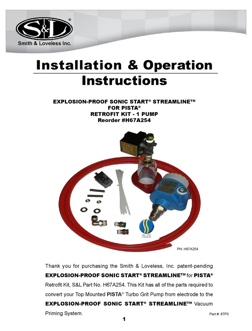
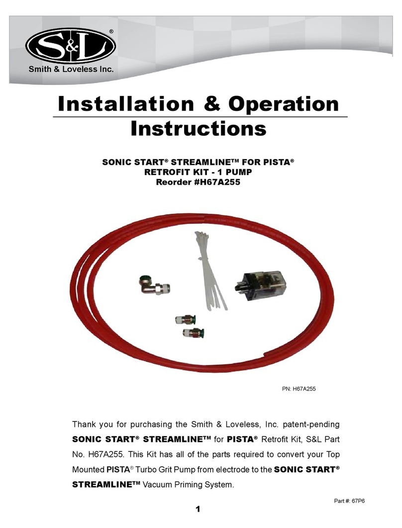
SMITH & LOVELESS SONIC START STREAMLINE H87A457 Installation instructions

1
SONIC START®STREAMLINETM RETROFIT KIT
EVERY PART REQUIRED TO UPGRADE
FROM SONIC START® TO SONIC START® STREAMLINE™
#H87A457 & #H87A459
Installation & Operation
Instructions
Smith & Loveless Inc.
Thank you for purchasing the Smith & Loveless, Inc. patented Sonic
Start®StreamlineTM Retrot Kit, S&L Part No. H87A457 & H87A459.
This kit is ideal for Smith & Loveless Vacuum Primed Pumps and Smith
& Loveless Vacuum Primed Pump Stations.
®
1Part #: 87P31

2
As you read this manual, please take extra notice of the bodily injury warnings
called out with the internationally known symbol seen here. We have inserted
these warnings to help ensure operator safety. Following the bodily injury
warning, one of the following three words will appear:
DANGER: Indicates an imminently hazardous situation which, if not avoid-
ed, will result in death or serious injury. These signs appear with a red back-
ground and white letters.
WARNING: Indicates a potentially hazardous situation which, if not avoided,
could result in death or serious injury. These signs appear with an orange
background and black letters.
CAUTION: Indicates a potentially hazardous situation which if not avoided
may result in minor or moderate injury. These signs appear with a yellow
background and black letters
OPERATOR SAFETY
TABLE OF CONTENTS
Topic Page
Operator Safety 2
Parts Included In Kit 3
Tools Required 4
Installation Steps 4
Operating Guide 19
Troubleshooting Guide 20
Recommended Replacement Parts 23
Warranty 23
Other Parts & Products 24
Keep these instructions with your equipment Operation & Maintenance Manual
once this kit is installed. This document also serves as the operation instructions
for the Sonic Start®Streamline™ System.
!
!
!
!

3
Item Quantity P/N Description
1 1 87B728 Dome & Solenoid Valve Assembly
2 2 6L200DH Stainless Steel Studs
3 2 6L65F Washers
4 2 6L30K Nuts
5 1 1L28B Close Nipple
6 1 1L764B Ball Valve
7 1 1L69B Pipe Plug
8 1 1L37B Street Tee
9 1 1L545A-2 DIN Connector Cable
10 6 5L150A Cable Ties
11 1 5L57C Cord Grip
12 1 5L57C-2 O-Ring for Cord Grip
13 1 5L57C-1 Nut for Cord Grip
14 1 4L406B Delay Timer
15 1 6L139CG Self Tapping Screw
16 2 5L75J Female Disconnect
17 1 87A455 Piping Assembly
18 12 ft. 1L142BC Tubing
19 1 87P31 Installation Instructions (This Document), not shown
PARTS INCLUDED IN KIT
Please make sure your kit contains all
of the parts and quantities noted in the
Item and Description sections above,
and assure that none of the parts are
damaged before starting to install this
kit. Report any damaged or missing
parts to the Smith & Loveless, Inc. Parts
Department at (800) 922-9048.
Your kit contains the following parts:
1
2
3
4
5
6
78
9
10
11
13
12
14
15
17
18
16
This manual is used for kits
H87A457 and H87A459.
Please note if you have
received kit H87A459 that
parts 1-4 on the list at the
left were installed on your
pump at the S&L factory
and will not be found in the
kit.

4
TOOLS REQUIRED
The following list of tools is required to complete this installation:
INSTALLATION STEPS
• Phillips Screwdriver
• Standard Screwdriver
• Adjustable Wrench or Set of Open End
Wrenches
• Socket Wrench and Extension, 3/8” drive
• ½” Socket
• 3/4” socket
• Wire, 14 gauge, red, green and white
• Wire cutters
• Wire strippers
• Wire crimpers
• Wire nuts
• Control Panel Schematic
• Teontape
• Plumbers’ Grease, Petroleum Jelly or
non pumice hand soap
• Drill – ½” drive
• 3/4” Drill Bit or Knockout (to put a
3/4” hole in the control panel)
• #20 Drill Bit
• Hammer
• Punch
• Knife
BEFORE YOU START!
Make sure you have the pump’s ow conditions monitored during this procedure to prevent
overow. Depending upon the ow conditions of the pump station, it may be necessary to pump
the wet well down to the “off” level oat. Some pump stations may require a Vac Truck on site
during this installation. Only work on one pump at a time, in case the wet well needs to be pumped
down. Close the plug valve for the pump that is going to be worked on.
CAUTION: Use proper personal safety equipment when installing this kit. Eye
protection, non-skid safety shoes, hard-hat, hearing protection and gloves must be
used for the appropriate condition. Failure to do so could result in bodily injury.
DANGER: Disconnect and lock out power before servicing the equipment. Failure to
do so could result in electrical shock, serious bodily injury or death.
!
!

5
Photo 1
Dome
Step 2:
Remove the existing dome assembly from
the motor adapter.
Step 1:
Turn off and lockout power to the unit.
Mounting Hardware
Compression Ring
Step 3:
Now apply plumbers grease, petroleum
jelly or non pumice hand soap to the o-ring
at the bottom of the dome assembly (Item
1). This will make it easy to install the
dome into the motor adapter or adapter
ring. Now install the dome into the motor
adapter or adapter ring. NOTE: Motor
adapter ring shown (see Photo 2).
Photo 2
1
Step 4:
Position the retainer compression ring of
the dome assembly (Item 1) so that the
holes line up with the studs (Item 2 or
existing). Install the washers (Item3) and
nuts (Item 4) to secure the retaining ring
(See Photo 3).
Photo 3
1 2
3
4
Compression Ring

6
Step 5:
Ifyoudo not havetheoptionalcompound
vaccum/air pressure gauges installed on
your station at the volute gauge port:
A. Remove the 1/4” pipe plug from
the volute discharge gauge port
(see Photo 4).
B. Put Teon® tape on both ends of the
close nipple (Item 5) and install
into the tapped hole on the volute
(see Photo 5).
C. Install the vacuum release ball valve
(Item 6) onto the close nipple
(Item 5) (see Photo 6).
D. Wrap the threads of the pipe plug
(Item 7) with Teon®tape and install
onto the other end of the vacuum
release ball valve (Item6)(seePhoto7).
OR
If you do have the optional pressure
gauges installed on your station:
A. Remove the gauge tubing from the
tubing tting on the volute discharge
(see Photo 8).
B. Remove the gauge piping assembly
from the volute (see Photo 9).
Photo 4
Photo 5
Photo 7
Photo 8
Photo 6
Photo 9
5 5 6
7
6

7
C. Put Teon® tape on the male threads
on the street tee (Item 8) and install
intothetappedholeon thevolute (see
Photo 10).
D. Put Teon® tape on the male threads
of the gauge piping assembly and
install on the street tee (Item 8) (see
Photo 11).
E. Put Teon® tape on both ends of the
close nipple (Item 5) and install into
the open port of the street tee (item
8)(see Photo 11).
F. Install the ball valve (Item 6) onto the
close nipple (Item 5) (see Photo 12).
G. Wrap the threads of the pipe plug
(Item 7) with Teon® tape and install
onto the other end of the ball valve
(see Photo 13).
H. Install the gauge tubing back into the
tubing tting of the gauge piping. Trim
the end of the tubing if necessary (see
Photo 13).
Photo 13
Photo 10
Photo 11
Photo 12
8
5
7
6
8

8
Step 6:
Close the ball valve (Item 6). The handle
should be perpendicular to the valve body
(Photo 14).
Step 7:
Find the solenoid valves on the control
panel wiring schematic. Typically they are
on page 2 and labeled SV1 and SV2. Look
to see if you have delay timers located on
the schematic right before the solenoids
(typically labeled TD1/TC and TD2/TC).
There are three different options for the
solenoid valve and delay timers and they
are:
Option 1 - Solenoid valve is mounted to
the control panel and there is already a
delay timer on the solenoid valve (most
stations before 2002). (see Diagram 1) If
you have this option, go to step 8.
Option 2 - Solenoid valve is mounted to
the control panel and there is no delay
timer on the solenoid valve (most stations
from 2002-2008) (see Diagram 2). If you
have this option, go to step 9.
Option 3 - Solenoid valve is mounted off
the vacuum pump and there is no delay
timer on the solenoid valve (usually on
FX stations or pump stations recently
upgraded to the larger ported solenoid
valve with kit H87A343A) (see Diagram
3). If you have this option, go to step 10.
Photo 14
Valve handle in closed position
Diagram 2 - Option 2 - Before
Diagram 1 - Option 1 - Before
Diagram 3 - Option 3 - Before
DANGER: Disconnect and lock
outpowerbeforeperformingany
electrical work. Failure to do so
could result in electrical shock, serious
bodily injury or death.
WARNING: All electrical work
should be performed by a
qualied electrician and per all
applicable codes. Failure to do so may
result in severe bodily injury or death.
!
!
6

9
Photo 17
12
11
Step 8:
OPTION 1: This is only for stations with
the solenoid valve mounted to the control
panel and with a delay timer on the
solenoid valve.
Connect the DIN connector (Item 9) to
the solenoid valve on the dome assembly
(Item 1) and tighten the connection screw
with a screw driver (see Photo 15). Run
the DIN connector cable (Item 9) back to
the control panel.
Run the cable along the motor conduit
cable and fasten it to the motor conduit
with cable ties (Item 10) (see Photo 16).
If a higher enclosure rating must be
maintained or if you want a separate cord
gripfortheDINconnectorcable(item9),
put a 3/4” hole in the control panel to install
the cord grip (item 11). Place the o-ring
(item 12) for the cord grip (item 11) onto
the cord grip body (item 11)(see photo
17) and run it up against the shoulder of
the cord grip.
OR
TheDINconnectorcable(item9) can be
run through an existing panel hole if the
enclosure is NEMA 1 rated. If you elect
to do it this way, a new hole in the control
panel does not need to be drilled.
Photo 15
1
9
Photo 16
910

10
Usethecord grip nut (item 13) to hold the
cord grip (item 11) in place. Run the DIN
connector cable (item 9) throughthecord
grip (item 11) or existing panel hole and
tighten the cord grip (item 11) to secure
the DIN connector cable (item 9) (see
Photo 18).
Find the connection where the solenoid
valve is wired to the black wire of the delay
timer. Typically, this is located in the wire
troughs (see Photo 19).
Connect the red wire of the DIN connector
cable (Item 9) to the black wire of the
existing delay timer. Connect the black
wire of the DIN connector cable (Item 9)
to neutral (see Photo 20) and connect
the white wire to ground (see Photo 21).
Photo 19
Wire Troughs
NOTE: Exact location will vary
depending on your conguration.
Photo 20 Photo 21
Photo 18
13
11

11
Diagram 4 shows the updated typical
schematic after changes have been made.
Removetheoldsolenoidvalvecompletely.
Itisrecommendedthattheholeisplugged
to protect the control panel (plug not
provided) (see Photo 22).
Make sure any loose wires have a wire nut
installedtotheendandthatallneutraland
ground wires are still tied together properly
(see Photo 23).
Go to step 11.
Photo 22
Photo 23
Diagram 4 - Option 1 - After
Step 9:
OPTION 2:This is only for stations with
the solenoid valve mounted to the control
panel and no delay timer on the solenoid
valve.
Connect the DIN connector (Item 9) to
the solenoid valve on the dome assembly
(Item 1) and tighten the connecting screw
with a screw driver (see Photo 24). Run
the DIN connector cable (Item 9) back to
the control panel.
Photo 24
1
9

12
Run the cable along the motor conduit and
fasten it to the motor conduit with cable
ties (Item 10) (see Photo 25).
If a higher enclosure rating must be
maintained or if you want a separate cord
gripfortheDINconnectorcable(item9),
put a 3/4” hole in the control panel to install
the cord grip (item 11). Place the o-ring
(item 12) for the cord grip (item 11) onto
the cord grip body (item 5)(see photo 26)
and run it up against the shoulder of the
cord grip.
OR
TheDINconnectorcable(item9) can be
run through an existing panel hole if the
enclosure is NEMA 1 rated. If you elect
to do it this way, a new hole in the control
panel does not need to be drilled.
Usethecord grip nut (item 13) to hold the
cord grip (item 11) in place (see Photo
27). Run the DIN connector cable (item 9)
through the cord grip (item 11) or existing
panel hole and tighten the cord grip (item
11) to secure the DIN connector cable
(item 9).
To install the new delay timer (Item 14) to
the back of the control panel, nd a spot in
the panel to mount the delay timer (Item
14)(see Photo 28).
Photo 28
14
Photo 27
13
11
Photo 26
12
11
Photo 25
910

13
Photo 29
Photo 30
15
14
Run a wire from the terminal block where
the solenoid valve was connected to one
of the pins on the delay timer (Item 14)
with one of the female disconnects (Item
16) (see Photo 32). Crimp the female
disconnect (Item 16) onto the wire to
secure it (see Photo 33).
Photo 32 Photo 33
16
14 16
Photo 31
NOTE: Exact location will vary
depending on your conguration.
Punch a mark on the panel through the
mounting hole on the timer (see Photo
29). Drill a hole with a #20 drill bit at the
punch mark.
Screw the self tapping screw (Item 15)
into the new hole to secure the timer to
the panel (see Photo 30).
The delay timer (Item 14) will be installed
inline directly before the solenoid valve.
Remove the numbered power wire from
the correct solenoid valve (not the ground
or neutral; this wire should be a red wire)
(see Photo 31). Many stations use wire
#4 for solenoid valve #1 and wire #6 for
solenoid valve #2, but consult your wiring
schematic for the correctly numbered wire
to remove.

14 Photo 37
Diagram 5 - Option 2 - After
Connect the red wire of the DIN connector
cable (Item 9) to the other tab of the delay
timer (Item 14) with the other female
disconnect (Item 16) (see Photo 34).
Secure the wire by crimping the female
disconnect (Item 16) .
Connect the black wire of the DIN
connector cable (Item 9) to neutral (see
Photo 35) and connect the white wire to
ground (see Photo 36).
Diagram5 shows a typical updated wiring
schematic with the delay timer (Item 14)
added.
Removetheoldsolenoidvalvecompletely.
It is recommended that the hole be
plugged to protect the control panel (plug
not provided). Make sure any loose wires
have a wire nut installed to the end and
that all neutral and ground wires are still
tied together properly.
Go to step 11.
Photo 34
16
14
Photo 36Photo 35
9
99

15
Step 10:
OPTION3:Thisisonlyforstationswiththe
solenoid valve mounted off the vacuum
pump and no delay timer on the solenoid
valve.
To install the new delay timer (Item 14) to
the back of the control panel, nd a spot
on the backpan to mount the delay timer
(see Photo 38).
Punch a mark on the panel through the
mounting hole on the timer. (see Photo
39) Drill a hole with a #20 drill bit at the
punch mark.
Screw the self tapping screw (Item 15)
into the new hole to secure the delay timer
(Item 14) to the panel (see Photo 40)
The delay timer (Item 14) will be installed
inline directly before the solenoid valve.
Run a wire from one of the terminals
on the delay timer (Item 14) with one of
the female disconnects (Item 16) (see
Photo 41) to the terminal block where
the red solenoid valve wire is connected.
(see Photo 43 next page) Remove the
existing red wire for the solenoid valve
from the terminal strip. Crimp the female
disconnect (Item 16) onto the wire to
secure it (see Photo 42).
Photo 40
15
14
Photo 39
Photo 38
14
Photo 42
16
14 16
Photo 41

16
Note: If the existing DIN connector will
reach the solenoid valve on the new dome
assembly, it can be used. Otherwise, use
the new DIN connector supplied with kit.
If the new DIN connector cable (Item 9)
is used, connect the black wire of the DIN
connector cable (Item 9) to neutral (see
Photo 44) and connect the white wire to
ground (see Photo 45).
Use a screwdriver to disconnect the DIN
connector on the existing solenoid valve.
Connect the new or existing DIN connector
cable (Item 9) to the new solenoid valve
(see Photo 46).
Wire the red wire of the DIN connector to
the other terminal of the delay timer (Item
14)with the other female disconnect (Item
16)(see Photo 47).
16
14
Photo 47
Photo 46
9
Photo 43
NOTE: Exact location will vary
depending on your conguration.
Photo 45Photo 44

17
Secure the wire by crimping the female
disconnect (Item 16)(see Photo 48).
Diagram 6 shows a typical updated schematic
with the delay timer (Item 14) added.
Step 11:
Remove all the vacuum ttings, vacuum tubing
and solenoid valve (if applicable) from the side
of the oat check valve that is not connected to
the vacuum pump. Apply Teon® tape to the
threads on the new piping assembly (Item 17)
and install it into the oat check valve. If there is
not enough space to install the piping assembly
(Item 17), the shut off valve and/or tee may be
removed from the assembly (see Photo 49).
Step 12:
Connect the vacuum tubing (Item 18) to the
quick disconnect tubing tting on the top of the
dome (Item 1)(see Photo 50). Run the tubing
from the dome to the new piping assembly
located next to the oat check valve (Item 17).
Insert the other end of the vacuum tubing (Item
18) into the quick disconnect 90 degree elbow
tting (Item 17) (see Photo 51).
Photo 49
17
Photo 51
18
117
Photo 50
18
Photo 48
16
Diagram 6 - Option 3 - After
Float Check Valve
Street Tee
Shut Off Valve
90-degree elbow

18
Step 13:
Run the vacuum tubing (Item 18) over to
thetopof theSonic Start® Streamline™
Vacuum Dome Assembly (Item 1) (see
Photo 52).
If your vacuum pumps are located under
the control panel, make sure there is an
arc in the tubing (Item 18) between the
dome and vacuum pump (see Photo 52)
Step 14:
Trim the vacuum tubing (Item18)tolength
so there are no large sags, but do leave a
little bit of slack (see Photo 52).
Step 15:
Remove any remaining vacuum tubing
from the previous sytem that is not being
used in the Sonic Start® Streamline™
Vacuum Priming System.
Step 16:
Perform a final check to make sure
everything is complete.
Check that all vacuum tubing
(Item 18) isinplaceandsecure
in the ttings (see Photo 53).
Check that the dome assembly
(Item1)issecureandrestrained
inthepumpadapter(seePhoto
54).
Check that all tools and unused
parts are removed from the
station.
Step 17:
Turn on the power and confirm that
the operation of the SONIC START®
StreamlineTM Prime Sensing System
is fully functional for this pump before
making any changes to other pumps.
Photo 54
11
Photo 53
20
Photo 52
118
Step 18:
Once the proper operation is conrmed
return to Step 1 if there are additional
pumps to upgrade.

19
Magnet
OPERATING
GUIDE
Liquid level in the pump priming chamber is
monitored by the SONIC START®resonant
frequency liquid level prime sensing probe
with piezoelectric drive and sensitive circuits
to detect frequency shifts when the SONIC
START® Prime Sensing Probe is covered by
liquid. If water covers the Sonic Start® Prime
Sensing Probe, it changes the natural frequency
andthe SonicStart®Relay, locatedinsideofthe
SONIC START® Prime Sensing Probe changes
state.
Sonic Start®Prime Sensing Probe
Indicating Lights
There are two (2) indicating lights in the
translucentplasticportionoftheSONICSTART®
Prime Sensing Probe. One light is Green and
one light is Red.
Power Indicating Light
A steady Green light indicates the SONIC
START® Prime Sensing Probe is receiving
power and can operate. The Green light will be
lit whenever the 120 VAC power for the pump
station or PISTA® Grit Chamber is turned on.
Primed Indicating Light
The Red light will be lit continuously when the
pump is not primed. The Red light will turn off
when the pump is primed.
Electrical Problems Indicating Light
A ashing Red light means that there is an
overload or short circuit in the SONIC START®
wiring or a problem with the SONIC START®
Prime Sensing Probe. See the Troubleshooting
Section of this manual to determine the problem.
Simulate The Priming Process
The SONIC START® comes with a means to
testtheSONIC START® Prime Sensing Probe.
This is done by changing the state of the relay
located inside of the SONIC START® Prime
Sensing Probe. Each SONIC START®comes
with a magnet that can be used to change the
state of the relay located inside of the SONIC
START® Prime Sensing Probe. This allows
the operator to simulate either a primed or not
primed operation. This is important for both
testing and troubleshooting the Sonic Start®.
To simulate the priming process, rst note which
state the SONIC START® is in:
Primed State (Green Light On,
Red Light Off) or
Not Primed State (Green Light
On, Red Light On).
Hold the magnet up against the target symbol
on the SONIC START® Prime Sensing Probe
for a few seconds to change the state of the
relay located inside the SONIC START® Prime
Sensing Probe. If the Red indicating light
changes state, the SONIC START® Prime
Sensing Probe is operating correctly.
Target Symbol

20
TROUBLESHOOTING
GUIDE
Troubleshooting 1
If the vacuum pump is running, but the pump
will not prime, follow the steps below until the
pump will prime.
1. Make sure there are no kinks in the
tubing and no cracks in the dome.
Replace any tubing that has been
kinked and replace any damaged
domes.
2. Remove the tubing from the dome. If
you can feel a vacuum on the tubing,
most likely there is a vacuum leak in
the system. Reinsert the tubing into
the dome and make sure that all of
the pieces of tubing are pushed in as
far as they will go, and are securely
installed into the tubing ttings.
TECHTIP: One method
that can be used to
check for leaks is to
apply shaving cream
on the connections of
the solenoid valve assembly, dome
assembly, and oat check valve. If
there is a leak in these parts, the
shaving cream will be sucked in at the
leak location. If the leak is conrmed
at a connection, tighten the ttings at
the leak location and try to prime the
pump again.
3. If tightening does not x the leak,
take the connection that is leaking
apart and put Teon tape or other
thread sealant on the male tting and
reassemble.
4. Check the reeds in the vacuum pump.
If the reeds are old and not providing
adequate vacuum, this could be an
additional reason you are having
priming problems.
5. Repeat steps 2 and 3 until all
leaks in the system are addressed.
6. If additional information or
assistance is needed, call
your Smith & Loveless, Inc.
Representative or the Smith &
Loveless, Inc. Parts Department at
(800) 922-9048.
Troubleshooting 2
If the pump runs, but it is not primed and both the
Red and Green indicating lights are Off follow
the steps below until the pump will prime.
1. If both the Red and Green indicating
lights on the SONIC START® Prime
Sensing Probe are not lit, the SONIC
START® is not getting power. You
have a power supply issue. Check
the Sonic Start®Din Connector
Cable (Item 9), and SONIC START®
Operating Module to make sure
everything is securely attached.
2. Continue checking the wiring until
the Green indicating light is lit. Once
power is restored to the SONIC
START® Prime Sensing Probe, the
pump will operate normally.
This manual suits for next models
1
Table of contents
Other SMITH & LOVELESS Water System manuals
Popular Water System manuals by other brands

Corsair
Corsair XC5 RGB Series quick start guide

Greenlife
Greenlife hybrid manager Installation and operation manual

Excalibur
Excalibur EWR 4050 Installation, operation & service manual

Culligan
Culligan Aquasential RO owner's guide

vollara
vollara W2000A manual

WaterGeneral
WaterGeneral RD-322 Installation & service manual
