Smith Performance Sprayers Industrial & Contractor Series User manual

Manual No. 183282
Rev A: 06/15/17
ECN17-010
5 1/2”X 8 1/2”Booklet
Do Not Return This Sprayer To The Store
For Help, Information or Parts, Call : 1-800-311-9903
The Fountainhead Group, Inc.
23 Garden St., New York Mills, NY 13417
1-800-311-9903
www.TheFountainheadGroup.com
www.smithperformancesprayers.com
CAUTION: Read and follow all instructions
Use and Care Manual
Stainless Steel
Compression Sprayer
Industrial and Contractor Series
S103E
#190448

Page 2
Do not return sprayer to store, if you experience problems or have questions contact
our toll free Customer Service Center, M-F 8A.M. - 5P.M., EST, at 1-800-311-9903, or
WARNING
The sprayer is operated with liquid under pressure. Failure to observe caution and to follow instructions
for operating and cleaning can cause tank, hose and other parts to be weakened and rupture under
pressure. This can result in serious injury from high pressure discharge of liquids or forcible ejection of
parts. Do not use ammable materials in this sprayer. Material could ignite or explode, causing serious
injury and/or possible death. For safe use of this product, you must read and follow all instructions before
use.
TEST SPRAYER WITH WATER BEFORE USING ANY CHEMICALS.
CAUTION
Always empty, clean and dry tank, pump system, shut-o, hose, and extension after each use. FAILURE TO
DO SO MAY WEAKEN SPRAYER COMPONENTS, CAUSING COMPONENTS TO RUPTURE WHEN PRESSURIZED.
Additionally, FAILURE TO CLEAN AND PROPERLY MAINTAIN YOUR SPRAYER WILL VOID MANUFACTURER’S
WARRANTY.
WARNING
ALWAYS CLEAN THE SPRAYER AND SHUT-OFF THOROUGHLY AFTER EACH USE
OR WHEN CHANGING APPLICATIONS AS DESCRIBED IN THE CLEANING SECTION.
FAILURE TO COMPLETELY CLEAN MAY CAUSE CROSS-CONTAMINATION.
SAFETY PRECAUTIONS
• Read owner’s manual completely before operating this sprayer.
• Always use goggles, gloves, and protective clothing when using sprayer. Refer to the appropriate
technical bulletin for the chemical being sprayed for additional protective clothing required.
• Read and follow all instructions and cautions on label, material safety data sheets and technical bulletins
of products used in this sprayer.
• Never use ammable liquids, chlorine, bleach, caustics, acids, hot water, or other corrosive solutions or
heat, pressure or gas producing chemicals in the tank for the S103E Sprayer.
• Do not leave sprayer in the sun when not in use.
• Spray when air is calm to prevent drift of chemicals.
• Do not use sprayer near open ame or anything that could cause ignition of the spray.
• Always inspect hose and all hose connections before each use. A damaged hose, or loose hose
connection can result in unintended exposure to the pressurized chemical, resulting in serious injury or
property damage.
• Do not lift or carry sprayer by the hose, shut-o valve, or extension. Carry by pump handle only,
making sure handle is properly locked in place before lifting.
• Do not pressurize with any mechanical device such as an air compressor, since this can create a
dangerous pressure level and bursting of parts resulting in serious injury. Only use original pump.
• Do not store chemicals in this tank.
• Always release pressure when sprayer is not in use and before removing pump from tank.
• Do not stand with face or body over top of tank when pumping or loosening pump, to prevent pump or
solution from striking you, resulting in serious injury.
• Clean and rinse sprayer thoroughly after each use.
• Never attempt to alter sprayer from original condition.
• Always use replacement parts from original manufacturer.
• Keep the sprayer and all chemicals out of the reach of children.

Page 3
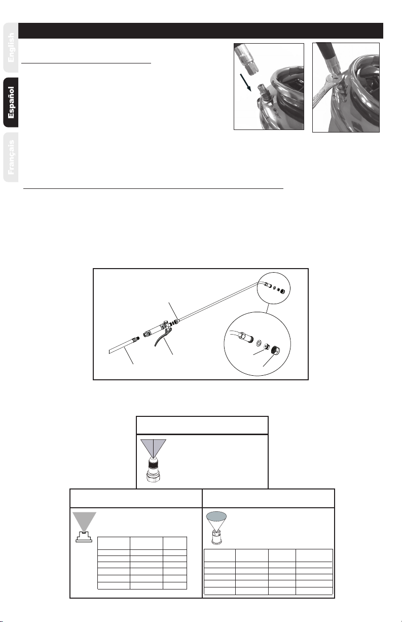
ASSEMBLY INSTRUCTIONS
Assemble Hose To Tank
1. Wrap teon tape around tank tting threads 2X in
clockwise direction, if needed.
2. Align hose and screw on to tank. (See Figure A).
3. Tighten with a 5/8”wrench. (See Figure B).
Figure B
Figure A
Assemble Hose, Extension, Shut-O & Nozzle
1. Attach hose to shut-o and tighten securely using a 9/16”wrench. Do not overtighten. Use a 3/4” wrench
to hold the shut-o handle while tightening the hose. (See Figure C)
2. Install the extension onto the shut-o assembly and tighten the nut securely using a 13/16”wrench.
(See Figure C)
3. Install selected nozzle into the extension nut and tighten nut securely using a 13/16”wrench.
(See Figure C)
80° FAN .07 GPM #4 GREEN
80°
80°
80°
80°
SPRAY
ANGLE: SPRAY
PATTERN:
FAN
FAN
FAN
FAN
FLOW
RATE:
.10 GPM
.13 GPM
.10 GPM
.20 GPM
COLOR
#6 RED
#10 BLACK
#8 GRAY
#12 BROWN
65° FAN .2 GPM
80°
80°
80°
95°
SPRAY
ANGLE: SPRAY
PATTERN:
FAN
FAN
FAN
FAN
FLOW
RATE:
.2 GPM
.5 GPM
.4 GPM
.5 GPM
110° FAN 1 GPM
BRASS FLAT FAN TIP
NOZZLE USES: CERAMIC CONEJET TIP
NOZZLE USES:
1. Industrial and Concrete Series (Orange)
Used on 1. Turf and Argiculture Series (Green)
2. Industrial and Concrete Series (Orange)
3. Cleaning and Restore Series (Blue)
4. Pest Control Series (White)
Used on
BRASS ADJUSTABLE
FAN NOZZLE USES:
1. Industrial and Concrete Series (Orange)
Used on
Figure C
HOSE
SHUT-OFF
EXTENSION
NUT
NOZZLE

Page 4
OPERATING INSTRUCTIONS
Filling
IMPORTANT: Always make sure the pressure is
released from the tank before lling or servicing.
1. Pull up on the knob of the pressure release
valve until all the pressure is released from the
tank. (See Figure D.)
Shut-O
1. Direct nozzle away from you and squeeze shut-o
lever to begin spraying.
2. This model does have a locking trigger.
Figure D
Pump Clamp Tab
Pump Unlocking And Pressurizing
TO PRESSURIZE: Push down on the handle to depress
coil spring and turn handle 1/4 turn counterclockwise to
unlock handle. Pressurize the sprayer by pumping the
handle in a smooth up and down motion. Push down on
the handle to depress coil spring and turn handle 1/4 turn
clockwise, then allow handle to raise into lock position.
TO UNLOCK PUMP: Turn handle counterclockwise
until 4-prong clamp is loose, then rotate clamp
counterclockwise aligning the tabs with the slots
in the neck of the tank and remove the pump.
TO LOCK PUMP: Align clamp tabs with the slots in the
neck of the tank and lower the pump assembly, rotate
the 4-tab clamp clockwise to the stop position and
rotate the handle clockwise to tighten, seal and lock the
tank cover.

Page 5
OPERATING INSTRUCTIONS CONTINUED
Steps To Cleaning Your Sprayer
*** To prevent clogging issues, after each use clean your sprayer.***
1. Release pressure in your sprayer via pressure relief valve. Do not undo handle without releasing pressure.
2. Empty remaining chemical back into original lling container.
3. Fill sprayer with water, place pump back into tank, and tighten.
4. Aggressively shake the water in the tank to try and get residue o of the inside walls of the sprayer. Repeat
step if necessary, each time relling with fresh water.
5. Pressurize the sprayer and spray water for 30-45 seconds into a disposable reservoir, then release pressure
and remove the pump from the tank.
6. Tip and empty tank, then set tank upright. Hold wand and shut-o above the tank and depress the
shut-o. The liquid will drain into the tank, empty again.
7. Repeat the steps above as necessary.
8. Allow tank to air dry by leaving the pump outside of tank over night. The next day, replace the pump to
keep debris out of the tank.
Pump Lubrication
Pump should be periodically oiled by applying 10 to
12 drops of light oil down the pump rod through the
opening in the pump cap as shown.
MAINTENANCE
Sprayer Storage
1. Sprayer tank should be hung upside down, with the pump removed.
2. Do not store or leave any solution in the tank after use.
3. Store in a warm, dry location out of direct sunlight.
4. Keep the sprayer and all chemicals out of reach of children.

Page 6
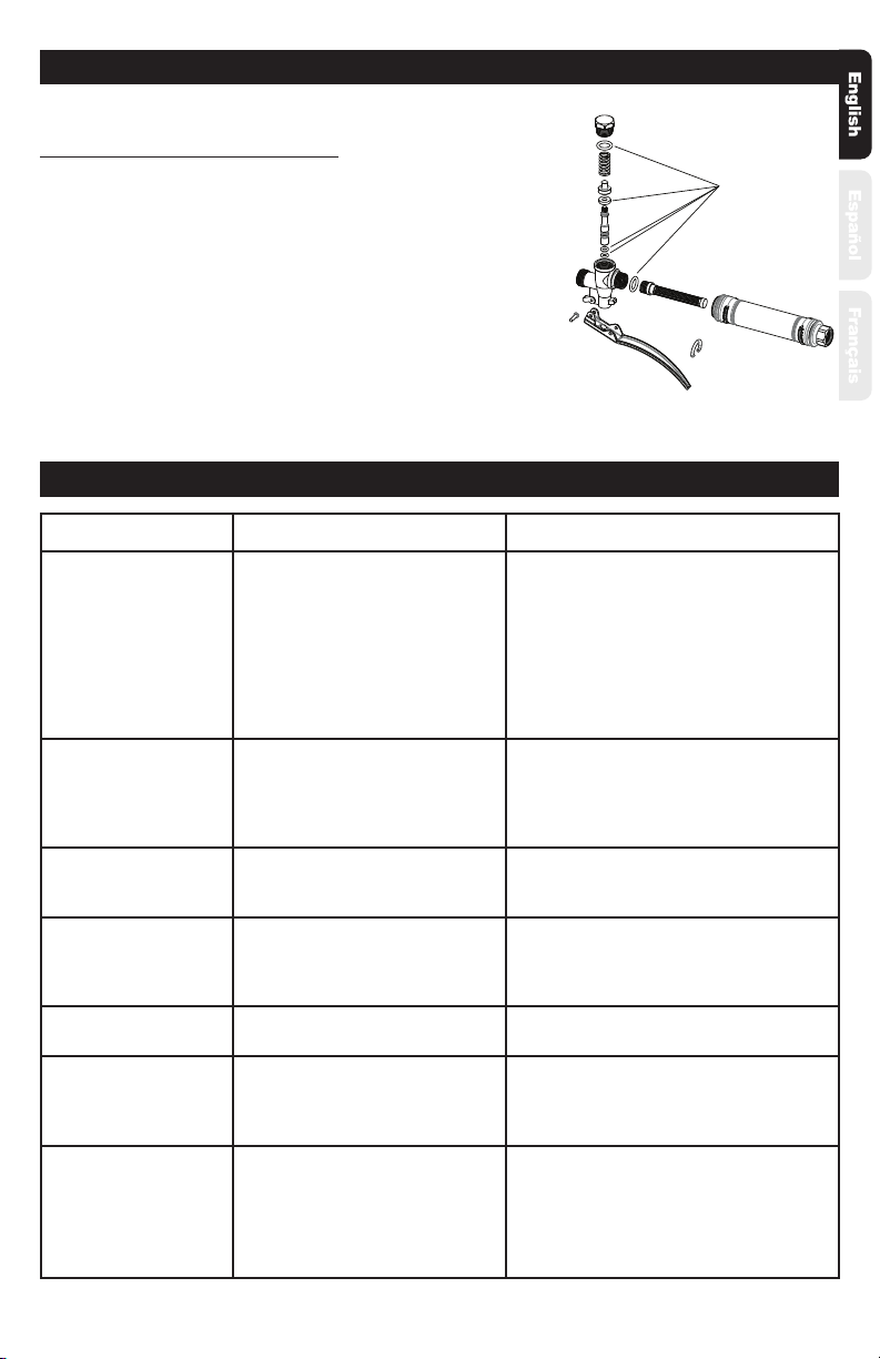
Pump Disassembly & Reassembly
NOTE: Remove pump from tank prior to disassembly.
Nozzle Maintenance
1. If nozzle clogs, remove and disassemble the nozzle assembly.
2. Clean the openings of any obstructions and reassemble.
3. The brass nozzles should be cleaned with toothbrush and detergent. Don’t use metal brush or sharp
objects on the nozzle. For tough clogs soak brass nozzle in xylene and clean with a brush.
1. Inspect tank cover o-ring. If worn or damaged, remove and replace. (See Figure E)
2. To remove tank cover from pump barrel, while rmly gripping tank cover, grasp pump barrel and
unscrew by turning counterclockwise as shown. (See Figure F) A strap wrench may be required to
loosen barrel.
3. Inspect barrel o-ring. If worn or damaged, remove and replace. Lubricate o-ring with petroleum jelly.
(See Figure G)
4. Inspect piston o-ring. If worn or damaged, remove and replace. Lubricate o-ring with petroleum jelly.
(See Figure H)
5. Inspect check valve in bottom of barrel. If worn or damaged, remove and replace by pressing into
hole in bottom of barrel. (See Figure J)
6. Insert the pump handle/piston assembly into the barrel. While rmly gripping the tank cover, thread
the pump barrel into the cover and tighten by turning clockwise. (See Figure K) A strap wrench may be
required to tighten barrel.
MAINTENANCE CONTINUED
Figure F
Figure E Figure G
Figure H Figure J Figure K
Page 7
TROUBLE LOOK FOR REMEDY
Sprayer leaks at pump or
sprayer does not build
pressure.
1. Dirt or debris on tank cover
o-ring. (#3H).
2. Chipped, torn, swollen, or
defective tank cover o-ring (3H).
3. Check valve (#3S) at bottom of
pump assembly.
4. Worn or damaged o-ring (#3L)
on piston.
1. Clean dirt or debris from o-ring (#3H) or
closure.
2. Remove old o-ring (#3H) and replace with
new as described in Pump Disassembly &
Reassembly section.
3. Replace if missing or damaged as described
in Pump Disassembly & Reassembly section.
4. Replace if worn or damaged as described in
Pump Disassembly & Reassembly section.
Sprayer material
overows through pump
barrel or pump handle
rises when handle is
unlocked.
1. Dirt or debris under check
valve (#3S) on pump.
2. Chipped, torn, or swollen
pump check valve (#3S).
1. Clean check valve (#3S) and valve sealing
surface on pump.
2. Replace check valve (#3S) as described
in Pump Disassembly & Reassembly section.
Hose leaks at tank or
shut-o.
1. Loose hose at tank.
2. Cracked, swollen, or faulty hose.
3. Loose hose at shut-o.
1. Tighten hose nut at tank.
2. Replace hose.
3. Tighten hose at shut-o.
Sprayer is dicult to
pump.
1. Damaged piston o-ring (#3L)
2. Piston o-ring (#3L) is dry.
1. Replace piston o-ring as described in
Pump Disassembly & Reassembly section.
2. Lubricate piston o-ring as described
in Pump Disassembly & Reassembly section.
Sprayer tank leaks. Evidence of spray material
escaping from the tank. Replace entire sprayer.
Nozzle drips when
shut-o lever is released.
1. Dirt or debris in shut-o valve.
2. Damaged o-rings or seals in
shut-o (Kit #10).
1. Clean shut-o as described in Shut-o
Maintenance section.
2. Service shut-o seals as described in
Maintenance service (Kit #10).
Nozzle tip leaks, poor
spray pattern, partial
spray or complete
stoppage.
1. Spray extension or nozzle
clogged.
2. Dirty or clogged nozzle tip.
1. Remove nozzle and clean as described in
Nozzle Maintenance section.
2. Clean the nozzle tip with a soft brush.
TROUBLESHOOTING
Shut-O Maintenance (Repair Kit)
Always depressurize sprayer before maintenance by activating
shut-o and spraying contents out.
1. Unscrew the handle from the shut-o assembly.
2. Unscrew valve cap and remove valve stem components and seals as
shown. Clean components with cool clean water.
3. Clean any debris from inside the handle and shut-o body. Check
for any wear of o-rings or seals and replace as necessary.
4. Reassemble the components as shown and tighten the handle and
valve cap securely.
MAINTENANCE CONTINUED
SEALS

Page 8
KITS, PARTS & ACCESSORIES
KIT #3
1
2
3A
3B
3D
3C
3E
3F
3G
3H
3J
3K
3L
3M
3N
3P
3R
3S
3C
6
8-1 8-2 8-3 8-4 8-5
7-1 7-2 7-3 7-4 7-5 7-6 8-6
10G
10F
10B
KIT #10
D
A
C
B
KIT #4 5
11-1
11-2
12
SHUT-OFF
9
10A
10B
10H
10G
10D 10C
10E
10F
10G
10C
10D
10E
10A
10H
Page 9
KITS, PARTS & ACCESSORIES CONTINUED
3A 182485 HANDLE, PUMP
3B 182711 HANDLE LOCKING COLLAR
3C 182704 SPRING (2)
3D 182484 4-TAB CLAMP
3E 182714 TANK COVER
3F 182712 FLAT WASHER
3G 182713 RETAINING RING
3H 182519 O-RING 105mm x 5.7mm, V
3J 182715 PUMP ROD
3K 182706 VALVE SEAT
3L 182523 O-RING 30mm x 4mm, V
3M 182707 PISTON PLATE
3N 182708 LOCKNUT
3P 182524 O-RING 46mm x 3.5mm,V
3R 182710 PUMP BARREL
3S 182535 CHECK VALVE, PUMP, V
KIT #3 182522 PUMP Viton
(Brown O-rings & Gasket)
KEY# PART# DESCRIPTION
5 182677 SHOULDER HARNESS
6 182567 NOZZLE, ADJUSTABLE, BRASS
7
-1 182578 FLAT FAN TIP, BRASS, .2 GPM-65°
-2 176042 FLAT FAN TIP, BRASS, .2 GPM-80°
-3 176116 FLAT FAN TIP, BRASS, .4 GPM-80°
-4 176171 FLAT FAN TIP, BRASS, .5 GPM-80°
-5 182577 FLAT FAN TIP, BRASS, .5 GPM-95°
-6 182576 FLAT FAN TIP, BRASS, 1 GPM-110°
8
-1 182795 NOZZLE, #4 GREEN POLY, .07 GPM-80°
-2 182796 NOZZLE, #6 RED POLY, .10 GPM-80°
-3 182797 NOZZLE, #10 BLACK POLY, .10 GPM-80°
-4 182784 NOZZLE, #8 GRAY POLY, .13 GPM-80°
-5 182798 NOZZLE, #12 BROWN POLY, .20 GPM-80°
-6 182785 NOZZLE, #8 BRASS CONICAL
9 183300 SHUT-OFF
A 182519 O-RING 105mm x 5.7mm, VITON
B 182535 CHECK VALVE, PUMP VITON
C 182523 O-RING 30mm x 4mm, VITON
D 182524 O-RING, 46mm x 3.5mm, VITON
KIT #4 182644 PUMP GASKETS VITON
(Brown O-rings & Gasket)
KIT #10 183525 SHUT-OFF SERVICE KIT
10A 182474 O-RING, 1.9mm x 4.2mm, VITON
10B 183304 VALVE STEM, BRASS
10C 182476 SEAL, VALVE, VITON
10D 183305 VALVE BASE, BRASS
10E 183306 SPRING, VALVE
10F 183303 CAP, VALVE
10G 182468 O-RING, 2.4mm x 11.2mm, VITON
10H 182467 FILTER
KEY# PART# DESCRIPTION
182521 3.5 GALLON TANK, VITON
(INCLUDES KEY #2)
2 182678 VITON PRV ASSEMBLY
1
KEY# PART# DESCRIPTION
11
-1 183294 24”WAND ASSEMBLY, BRASS
-2 183296 NUT, BRASS CAP
12 183381 HOSE ASSEMBLY
SERVICE KITS, PARTS & ACCESSORIES ARE AVAILABLE BY CONTACTING
The Fountainhead Group, Inc. - Customer Service Center
Monday - Friday 8 A.M. - 5 P.M., EST
Toll Free: 1-800-311-9903
or
e-mail: [email protected]
or
Access online at: www.TheFountainheadGroup.com
www.smithperformancesprayers.com

No devuelva este atomizador a la tienda
Para obtener ayuda, información o partes, llame al:
1-800-311-9903
The Fountainhead Group, Inc.
23 Garden St., New York Mills, NY 13417
1-800-311-9903
www.TheFountainheadGroup.com
www.smithperformancesprayers.com
PRECAUCIÓN: Lea y siga todas las instrucciones
Serie industrial y para contratista
S103E
#190448
Atomizador industrial de
acero inoxidable
Manual de uso y cuidado
Manual No. 183282
Rev A: 06/15/17
ECN17-010
5 1/2”X 8 1/2”Booklet

No devuelva el atomizador a la tienda, si tiene problemas, o si tiene preguntas póngase en
contacto con nuestro Centro de Servicio al Cliente al número gratuito, de lunes a viernes
de 8:00 a.m. a 5:00 p.m., hora del Este, al 1-800-311-9903, o por correo electrónico:
ADVERTENCIA
El atomizador funciona con líquido a presión. El no proceder con precaución ni seguir las instrucciones de
operación y limpieza puede ocasionar que el tanque, la manguera y otras partes se debiliten y se agrieten
al someterse a presión. Esto puede ocasionar lesiones graves por descarga de líquidos a alta presión o por
expulsión forzada de las piezas. No utilice materiales inamables en este atomizador. El material podría
encenderse o explotar, causar lesiones graves y/o posiblemente la muerte. Para un uso seguro de este
producto, debe leer y seguir todas las instrucciones antes de usarlo.
PRUEBE EL ATOMIZADOR CON AGUA ANTES DE UTILIZAR
CUALQUIER PRODUCTO QUÍMICO.
PRECAUCIÓN
Siempre vacíe, limpie y seque el tanque, el sistema de bombeo, el dispositivo de cierre, la manguera y la
extensión después de cada uso. EL NO HACERLO PUEDE DEBILITAR LOS COMPONENTES DEL ATOMIZADOR,
OCASIONANDO QUE SE AGRIETEN AL APLICAR PRESIÓN. Además, NO LIMPIAR NI DAR EL MANTENIMIENTO
ADECUADAMENTE ANULARÁ LA GARANTÍA DEL FABRICANTE DE SU ATOMIZADOR .
ADVERTENCIA
LIMPIE SIEMPRE EL ATOMIZADOR Y APÁGUELO COMPLETAMENTE DESPUÉS DE CADA USO O AL
CAMBIAR DE APLICACIONES COMO SE INDICA EN LA SECCIÓN DE LIMPIEZA. NO LIMPIARLO
COMPLETAMENTE PUEDE CAUSAR CONTAMINACIÓN CRUZADA.
PRECAUCIONES DE SEGURIDAD
• Lea el manual del propietario antes de operar este equipo.
• Use siempre gafas de seguridad, guantes y ropa de protección cuando utilice el atomizador. Consulte el
boletín técnico apropiado para ver la ropa de protección requerida para el producto químico a ser rociado.
• Lea y siga todas las instrucciones y precauciones de las etiquetas, de las hojas de datos de seguridad y de
los boletines técnicos de los productos utilizados en este atomizador.
• Nunca use líquidos inamables, cloro, blanqueador, agua caliente, productos cáusticos, u otras soluciones
corrosivas o calor, presión o productos químicos que produzcan gases en el tanque del atomizador S103E.
• No deje el atomizador en el sol cuando no esté en uso.
• Rocíe cuando el aire está en calma para evitar la dispersión de sustancias químicas.
• No utilice el atomizador cerca de llamas abiertas o de cualquier otra cosa que pueda causar la ignición del
producto pulverizado.
• Inspeccione siempre la manguera y todas las conexiones de la manguera antes de cada uso. Una
manguera dañada, o una conexión suelta puede provocar una exposición involuntaria al producto
químico a presión, lo que puede conducir a lesiones graves o a daños materiales.
• No levante ni transporte el atomizador tomándolo por la manguera, por la válvula de cierre, o por la
extensión. Transpórtelo sólo con el asa de la bomba , asegurándose de que el asa esté correctamente
asegurada antes de levantar la bomba.
• No lo someta a presión con ningún dispositivo mecánico como por ejemplo un compresor de aire, ya que
esto puede crear un nivel de presión peligroso y la rotura de piezas que puede dar lugar a lesiones graves.
Sólo utilice la bomba original.
• No almacene productos químicos en este tanque.
• Libere siempre la presión cuando el atomizador no esté en uso y antes de retirar la bomba del tanque.
• No ponga la cara o el cuerpo sobre la parte superior del tanque al estar bombeando o al desenganchar la
bomba, para evitar que la bomba o la solución lo impacte y ocasione lesiones graves.
• Limpie y enjuague perfectamente el atomizador después de cada uso.
• Nunca intente alterar el atomizador de su estado original.
• Use siempre piezas de repuesto del fabricante original.
• Mantenga el atomizador y todos los productos químicos fuera del alcance de los niños.
Página 11
Página 12
INSTRUCCIONES DE ENSAMBLAJE
Ensamble la manguera en el tanque
1. Enrolle 2 vueltas de cinta de teón hacia la derecha
alrededor de la conexión del tanque, si es necesario.
2. Alinee la manguera y atorníllela al tanque. (Vea la gura A).
3. Apriétela rmemente con una llave de 5/8”.
(Vea la gura B).
Figura B
Figura A
Ensamble la manguera, la extensión, el dispositivo de cierre y la boquilla
1. Conecte la manguera al dispositivo de cierre y apriete rmemente usando una llave de 9/16”. No apriete
demasiado. Utilice una llave de 3/4”para sujetar el mango del dispositivo de cierre mientras aprieta la
manguera. (Vea la gura C).
2. Instale la extensión en el conjunto del dispositivo de cierre y apriete la tuerca rmemente con una llave
de 13/16”. (Vea la gura C).
3. Instale la boquilla seleccionada en la tuerca de la extensión y apriete la tuerca rmemente con una llave
de 13/16”. (Vea la gura C).
USOS DE BOQUILLAS DE
ABANICO AJUSTABLE DE BRONCE:
Utilizadas en 1. Serie para césped y agricultura (Verde)
2. Serie industrial y de concreto (Naranja)
3. Serie para limpieza y restauración (Azul)
4. Serie para control de plagas (Blanco)
Utilizadas en
USO DE BOQUILLAS DE PUNTA
DE BRONCE DE ABANICO PLANO: USO DE BOQUILLAS DE PUNTA DE
CERÁMICA DE CHORRO CÓNICO:
ABANICO
ABANICO
ABANICO
ABANICO
ABANICO
65°
80°
80°
80°
95°
110° ABANICO
ÁNGULO DE
ATOMIZADO:
.2 GPM
.2 GPM
.5 GPM
.4 GPM
.5 GPM
1 GPM
TASA DE
FLUJO:
PATRÓN DE
ATOMIZADO:
80° .07 GPM #4 VERDE
80°
80°
80°
80°
.10 GPM
.13 GPM
.10 GPM
.20 GPM
COLOR
#6 ROJO
#10 NEGRO
#8 GRIS
#12 MARRÓN
TASA DE
FLUJO:
PATRÓN DE
ATOMIZADO:
ABANICO
ABANICO
ABANICO
ABANICO
ABANICO
ÁNGULO DE
ATOMIZADO:
Utilizadas en
1. Serie industrial y de concreto (Naranja)
1. Serie industrial y de concreto (Naranja)
Figura C
Manguera
Cierre
Extensión
Nuez
Boquilla

INSTRUCCIONES DE OPERACIÓN
Llenado
IMPORTANTE: Asegúrese siempre de liberar la presión del
tanque antes de llenarlo o de darle servicio.
1. Jale la perilla de la válvula de liberación de presión hasta
liberar toda la presión del tanque. (Vea la gura D).
Dispositivo de cierre
1. Dirija la boquilla lejos de usted y apriete la palanca para empezar
a rociar.
2. Este modelo tiene una disparadora de bloqueo.
Figura D
Lengüeta de la abrazadera de la bomba
Desbloqueo y presurizado de la bomba
PARA PRESURIZAR: Presurice el atomizador bombe-
ando con el asa en un movimiento suave ascendente y
descendente. Empuje el asa hacia abajo para presionar
el resorte helicoidal y gire el asa 1/4 de vuelta hacia la
derecha, y luego deje que el asa se eleve hasta su posición
de bloqueo.
PARA DESBLOQUEAR LA BOMBA: Gire el asa hacia
la izquierda hasta que quede suelta la abrazadera
de 4 puntas, a continuación, gire la abrazadera
hacia la izquierda alineando las pestañas con las
ranuras en el cuello del tanque y retire la bomba.
PARA BLOQUEAR LA BOMBA: Alinee las lengüetas de
la abrazadera con las ranuras en el cuello del tanque
y baje la bomba, gire la pestaña de la abrazadera de 4
puntas hacia la derecha a la posición de tope y gire el
asa hacia la derecha para apretar, sellar y cerrar la tapa
del depósito.
Página 13

Página 14
OPERATING INSTRUCTIONS CONTINUED
Pasos para limpiar el atomizador
*** Para evitar problemas de obstrucción, después de cada uso limpie el atomizador.***
1. Libere la presión en el atomizador a través de la válvula de alivio de presión. No suelte la manija sin
liberar antes la presión.
2. Descargue el producto químico remanente en su recipiente original.
3. Llene el atomizador con agua, vuelva a colocar la bomba en el tanque, y apriétela.
4. Agite vigorosamente el agua en el tanque para tratar de disolver los residuos de las paredes interiores
del atomizador. Repita este paso, cada vez que rellene el tanque con agua.
5. Presurice el pulverizador y rocíe el agua durante 30 a 45 segundos en un depósito desechable, luego
libere la presión y quite la bomba del tanque.
6. Incline y vacíe el tanque, y a continuación póngalo en posición vertical. Sostenga la extensión y el
dispositivo de cierre por encima del tanque y presione el dispositivo de cierre. El líquido drenará dentro
del tanque, vuelva a vaciarlo.
7. Repita los pasos anteriores según sea necesario.
8. Seque el tanque al aire, dejando la bomba fuera del tanque durante la noche. Al día siguiente, vuelva a
poner la bomba para impedir que los residuos entren al tanque.
Lubricación de la bomba
La bomba debe ser lubricada periódicamente aplicando
de 10 a 12 gotas de aceite ligero abajo del eje de la bomba
a través de la abertura en la tapa de la bomba como se
muestra.
MANTENIMIENTO
Almacenamiento del atomizador
1. El tanque del atomizador se debe colgar boca abajo, habiendo quitado la bomba.
2. No almacene ni deje ninguna solución en el tanque después de usarlo.
3. Almacénelo en un lugar templado y seco, lejos de la luz solar directa.
4. Mantenga el atomizador y todos los productos químicos fuera del alcance de los niños.

Desmontaje y montaje de la bomba
NOTA: Retire la bomba del tanque antes de desmontarla.
Mantenimiento de la boquilla
1. Si se obstruye la boquilla, quítela y desármela.
2. Limpie las obstrucciones de las aberturas y vuelva a armarla.
3. Las boquillas de bronce deben limpiarse con un cepillo de dientes y detergente. No utilice un cepillo
metálico ni objetos alados en la boquilla. Para obstrucciones difíciles remoje la boquilla de bronce en
xileno y límpiela con un cepillo.
1. Inspeccione la junta tórica de la tapa del tanque. Si está desgastada o dañada, quítela y reemplácela.
(Vea la gura E).
2. Para retirar la cubierta del tanque del cilindro de la bomba, mientras sujeta rmemente la tapa del
tanque, agarre el cilindro de la bomba y desenrósquelo girando hacia la izquierda como se muestra.
(Vea la gura F) Podría ser necesario una llave de correa para aojar el cilindro.
3. Inspeccione la junta tórica del cilindro. Si está desgastada o dañada, quítela y reemplácela. Lubrique la
junta tórica con vaselina. (Vea la gura G).
4. Inspeccione la junta tórica del pistón. Si está desgastada o dañada, quítela y reemplácela. Lubrique la
junta tórica con vaselina. (Vea la gura H).
5. Inspeccione la válvula de retención en la parte inferior del cilindro. Si está desgastada o dañada, quítela y
reemplácela haciendo presión dentro del oricio en la parte inferior del cilindro. (Vea la gura J).
6. Introduzca la manija/pistón de la bomba en el cilindro. Mientras sujeta rmemente la tapa del tanque,
enrosque el cilindro de la bomba en la tapa y apriételo girándolo hacia la derecha (Vea la gura K)
Podría ser necesario una llave de correa para apretar el cilindro.
CONTINÚA MANTENIMIENTO
Figura FFigura E Figura G
Figura H Figura J Figura K
Página 15

Mantenimiento del dispositivo de cierre de la válvula
(Juego de reparación)
Despresurice siempre el atomizador antes de darle mantenimiento
activando el dispositivo de cierre y atomizando el contenido.
1. Desenrosque la manija del dispositivo de cierre.
2. Desenrosque la tapa de la válvula y retire los componentes del vástago de
la válvula y los sellos como se muestra. Limpie los componentes con agua
limpia y fría.
3. Limpie todos los residuos del interior de la manija y del dispositivo de cierre.
Verique si hay algún desgaste de la junta, de la junta tórica o de los sellos
mientras lo lava con agua fría y limpia.
4. Vuelva a ensamblar los componentes como se muestra y apriete todas las
conexiones.
CONTINÚA MANTENIMIENTO
PROBLEMA BUSCAR SOLUCIÓN
El atomizador tiene una
fuga en la bomba o no
adquiere
presión.
1. Suciedad o residuos en la junta
tórica de la tapa del tanque (#3H).
2. Junta tórica de la tapa del tanque
astillada, rasgada, dilatada, o
defectuosa (3H).
3. Válvula de retención (#3S) en la
parte inferior de la bomba.
4. Junta tórica del pistón gastada o
dañada (#3L).
1. Limpie la suciedad o los residuos de la junta
tórica (#3F) o el cierre.
2. Retire la junta tórica (#3H) y reemplácela
con una nueva como se describe en la sección
Desensamblar y volver a ensamblar la bomba.
3. Reemplace si falta o está dañada, como se
describe en la sección Desensamblar y volver a
ensamblar la bomba.
4. Reemplace si está gastada o dañada como se
describe en la sección Desensamblar y volver a
ensamblar la bomba.
El material del
atomizador se
derrama por el cilindro de
la bomba o el mango de
la bomba se eleva cuando
se lo destraba.
1. Suciedad o residuos debajo de
la válvula de retención (# 3S) en la
bomba.
2. Válvula de retención de la bomba
(#3S) astillada, rasgada, o dilatada.
1. Limpie la válvula de retención (# 3S) y la
supercie sellada de la válvula en la bomba.
2. Reemplace la válvula de retención (#3S) como
se describe en la sección Desensamblar y volver
a ensamblar la bomba.
Fugas de la manguera en
el tanque o en el
dispositivo de cierre.
1. Manguera suelta en el tanque.
2. Manguera agrietada, dilatada o
defectuosa.
3. Manguera suelta en el dispositivo
de cierre.
1. Apriete la tuerca de la manguera en el tanque.
2. Cambie la manguera.
3. Apriete la manguera en el dispositivo de cierre.
Atomizador difícil de
bombear.
1. La junta tórica del pistón (#3L) está
dañada.
2. La junta tórica del pistón (#3L) está
seca.
1. Reemplace la junta tórica del pistón como se
describe en la sección Desensamblar y volver a
ensamblar la bomba.
2. Lubrique la junta tórica del pistón como se
describe en la sección Desensamblar y volver a
ensamblar la bomba.
El tanque del atomizador
tiene una fuga.
Hay evidencia de escape de material
de rociado del tanque. Reemplace todo el atomizador.
La boquilla gotea cuando
se suelta la palanca del
dispositivo de cierre.
1. Suciedad o residuos en la válvula
de cierre.
2. Juntas tóricas o sellos en el cierre
dañados (Juego #10)
1. Limpie el dispositivo de cierre tal como se
describe en la sección de Mantenimiento del
dispositivo de cierre.
2. Dele mantenimiento a los sellos del dispositivo
de cierre como se describe en Servicio de
mantenimiento (Juegos #10).
La punta de la boquilla
tiene fugas, un patrón
de rociado débil, rociado
parcial o un bloqueo
completo.
1. La extensión de rociado o la
boquilla están obstruidos.
2. La punta de la boquilla está sucia u
obstruida.
1. Retire la boquilla y límpiela como se describe en
la sección Mantenimiento de la boquilla.
2. Limpie la punta de la boquilla con un cepillo
suave.
SOLUCIÓN DE PROBLEMAS
Página 16
Juntas tóricas
y sellos

JUEGOS, PARTES Y ACCESORIOS
JUEGO #3
1
2
3A
3B
3D
3C
3E
3F
3G
3H
3J
3K
3L
3M
3N
3P
3R
3S
3C
6
8-1 8-2 8-3 8-4 8-5
7-1 7-2 7-3 7-4 7-5 7-6 8-6
D
A
C
B
JUEGO #4
5
11-1
11-2
12
Página 17
10G
10F
10B
JUEGO #10
CIERRE
9
10A
10B
10H
10G
10D 10C
10E
10F
10G
10C
10D
10E
10A
10H

KITS, PARTS & ACCESSORIES CONTINUED
3A 182485 ASA DE LA BOMBA
3B 182711 MANGO DEL COLLARÍN DE CIERRE
3C 182704 RESORTES (2)
3D 182484 ABRAZADERA DE 4 PUNTAS
3E 182714 TAPA DEL TANQUE
3F 182712 ARANDELA PLANA
3G 182713 ANILLO DE RETENCIÓN
3H 182519 JUNTA TÓRICA 105 mm x 5.7
mm, V
3J 182715 VARILLA DE LA BOMBA
3K 182706 ASIENTO DE LA VÁLVULA
3L 182523 JUNTA TÓRICA 30 mm x 4 mm, V
3M 182707 PLACA DEL PISTÓN
3N 182708 CONTRATUERCA
3P 182524 JUNTA TÓRICA 46 mm x 3.5 mm, V
3R 182710 CILINDRO PARA BOMBA
3S 182535 VÁLVULA DE RETENCIÓN PARA
BOMBA, V
JUEGO #3 182522 BOMBA, Viton
(Juntas tóricas y empaques marrón)
# DE
CLAVE
# DE
PIEZA
DESCRIPCIÓN
5 182677 ARNÉS PARA HOMBRO
6 182567 BOQUILLA AJUSTABLE DE BRONCE
7
-1 182578 ABANICO PLANO CON PUNTA DE
POLICARBONATO, .2 GALONES POR
MINUTO-65°
-2 176042 ABANICO PLANO CON PUNTA DE BRONCE,
.2 GALONES POR MINUTO-80°
-3 176116 ABANICO PLANO CON PUNTA DE LATÓN, .4
GALONES POR MINUTO-80°
-4 176171 ABANICO PLANO CON PUNTA DE BRONCE,
.5 GALONES POR MINUTO-80°
-5 182577 ABANICO PLANO CON PUNTA DE
POLICARBONATO, .5 GALONES POR
MINUTO-95°
-6 182576 ABANICO PLANO CON PUNTA DE BRONCE,
1 GALÓN POR MINUTO-110°
8
-1 182795 BOQUILLA, #4 VERDE DE POLICARBONATO,
.07 GALONES POR MINUTO-80°
-2 182796 BOQUILLA, #6 ROJA DE POLICARBONATO,
.10 GALONES POR MINUTO-80°
-3 182797 BOQUILLA, #10 NEGRA DE
POLICARBONATO, .10 GALONES POR
MINUTO-80°
-4 182784 BOQUILLA, #8 GRIS DE POLICARBONATO,
.13 GALONES POR MINUTO-80°
-5 182798 BOQUILLA, #12 MARRÓN DE
POLICARBONATO, .20 GALONES POR
MINUTO-80°
-6 182785 BOQUILLA CÓNICA, #8 DE BRONCE
9 183300 DISPOSITIVO DE CIERRE
A 182519 JUNTA TÓRICA 105 mm x 5.7 mm,
VITON
B 182535 VÁLVULA DE RETENCIÓN PARA
BOMBA, VITON
C 182523 JUNTA TÓRICA 30 mm x 4 mm,
VITON
D 182524 JUNTA TÓRICA 46 mm x 3.5 mm,
VITON
JUEGO #4 182644 EMPAQUETADURAS DE
LA BOMBA, VITON
(Juntas tóricas y empaques marrón)
JUEGO #10 183525 JUEGO PARA SERVICIO DE
DISPOSITIVO DE CIERRE
10A 182474 JUNTA TÓRICA, 1.9mm x 4.2mm, VITON
10B 183304 VÁSTAGO DE LA VÁLVULA DE BRONCE
10C 182476 VÁLVULA DEL SELLO, VITON
10D 183305 BASE DE LA VÁLVULA DE BRONCE
10E 183306 RESORTE DE LA VÁLVULA
10F 183303 TAPA DE LA VÁLVULA
10G 182468 JUNTA TÓRICA, 2.4mm x 11.2mm, VITON
10H 182467 FILTRO
# DE
CLAVE
# DE
PIEZA
DESCRIPCIÓN
1
182521 TANQUE DE 3.5 GALONES, VITON
(INCLUYE LLAVE #2)
2 182678 ENSAMBLAJE DEL PRV VITON
# DE
CLAVE
# DE
PIEZA
DESCRIPCIÓN
11 -1 183294 ENSAMBLE DE EXTENSIÓN DE 24”
PARA BRONCE
-2 183296 TUERCA DE LA TAPA DE BRONCE
12 183381 ENSAMBLAJE DE LA MANGUERA
Página 18

Página 19
LOS JUEGOS PARA SERVICIO, LAS PIEZAS Y LOS ACCESORIOS ESTÁN
DISPONIBLES CONTACTANDO A
The Fountainhead Group, Inc. - Centro de Servicio al Cliente
Lunes a viernes de 8 am a 5 pm hora del este
Número gratuito: 1-800-311-9903
o al
correo electrónico: Info@TheFGI.com
o al
en línea en: www.TheFountainheadGroup.com
www.smithperformancesprayers.com

Ne pas rapporter ce pulvérisateur au magasin de vente.
Pour contacter les services Assistance, Renseignements et
Pièces détachées, appeler le: +1-800-311-9903
The Fountainhead Group, Inc.
23 Garden St., New York Mills, NY 13417
1-800-311-9903
www.TheFountainheadGroup.com
www.smithperformancesprayers.com
Notice d’utilisation et d’entretien
Série Industrie et entreprises du bâtiment
S103E
#190448
Pulvérisateur à pression
préalable en acier inoxydable
ATTENTION: lire attentivement et suivre
scrupuleusement le mode d’emploi.
Manual No. 183282
Rev A: 06/15/17
ECN17-010
5 1/2”X 8 1/2”Booklet
Other manuals for Industrial & Contractor Series
2
This manual suits for next models
2
Table of contents
Languages:
Other Smith Performance Sprayers Paint Sprayer manuals

Smith Performance Sprayers
Smith Performance Sprayers S103E User manual

Smith Performance Sprayers
Smith Performance Sprayers PERFORMANCE S100 User manual

Smith Performance Sprayers
Smith Performance Sprayers 190450 User manual

Smith Performance Sprayers
Smith Performance Sprayers S103EX User manual

Smith Performance Sprayers
Smith Performance Sprayers S103E User manual

Smith Performance Sprayers
Smith Performance Sprayers Industrial & Contractor Series User manual

Smith Performance Sprayers
Smith Performance Sprayers Industrial & Contractor Series User manual


