Smiths Graseby MS16A Operating manual

Smiths Medical Publications
This publication has been compiled and approved by Smiths
Medical for use with their respective products. It is supplied in
this format to permit users to access the text and illustrations
for their own use e.g. training and educational purposes.
Users of the equipment must ensure that they have read and
understood the contents of the complete manual including the
warnings and cautions and have been trained in the correct use
of the product.
Smiths Medical cannot be held responsible for the accuracy and
any resulting incident arising from information that has been
extracted from this publication and compiled into the users
documentation.
This publication maybe subject to revision and it is the users
responsibility to ensure that the correct version of manual/
text/illustration is used in conjunction with the equipment.
Technical Service
Manual
Part Number 00SM-0105-6
Issue 6 (February 2005)
© 2005 Smiths Medical family of companies. All rights reserved.
Graseby®MS16A
Syringe Driver
SM0105-COV-6.PMD 2/23/2005, 12:12 PM1

MS16A Syringe Driver
Technical Ser vice Manual Issue 6 (February 2005) Page i
Smiths Medical
Published by Smiths Medical.
All possible care has been taken in the preparation of this
publication, but Smiths Medical, accepts no liability for any
inaccuracies that may be found.
Smiths Medical reserves the right to make changes without notice
both to this publication and to the product which it describes.
Copyright © 2005 Smiths Medical family of companies. All rights
reserved.
No part of this publication may be reproduced, transmitted,
transcribed, or stored in a retrieval system or translated into any
human or computer language in any form or by any means without
the prior permission of Smiths Medical.
Smiths Medical MD, Inc.
1265 Grey Fox Road, St. Paul, MN 55112, U.S.A.
European Representative:
Smiths Medical International Limited
Watford, Hertfordshire,
United Kingdom, WD24 4LG
http://www.smiths-medical.com
Registered in England. Company number 362847
Trademarks and acknowledgements:
“Graseby” and “Smiths” are trademarks of the Smiths Medical family
of companies.
All other trademarks are acknowledged as the property of their
respective owners.
SM0105-CON-6.PMD 2/23/2005, 12:12 PM1

MS16A Syringe Driver
Page ii Issue 6 (February 2005) Technical Service Manual
Smiths Medical
DROCEREUSSI
eussI
.oN egnahcrofnosaeR segaP
detceffe etaD
5launaMfoeussi-eRllA0002yaM
6etaroproC.deddastnairavSUdnaxobkcoL
.egnahc.d.i llA5002yraurbeF
SM0105-CON-6.PMD 2/23/2005, 12:12 PM2

MS16A Syringe Driver
Technical Ser vice Manual Issue 6 (February 2005) Page iii
Smiths Medical
Scope of this manual
This manual enables service personnel to service and repair the
MS16A Syringe Driver. It has been updated to incorporate Lockbox
information and the US variant.
Related manuals
Refer to the following Instruction Manual when more detailed
operating information is required. The Service Manual contains basic
driver operation information only.
zMS16A Syringe Driver, MS26 Syringe Driver Instruction
Manual, part number 0105-0549-A
Smiths Medical service contacts
In the event of any queries or problems that cannot be resolved by
this manual, please contact the appropriate Service/ Repair Centre.
UK address
SMITHS MEDICAL INTERNATIONAL LIMITED
Repair Centre
WATFORD
WD24 4LG
ENGLAND
TEL: (+44) (0) 1923 246434 FAX: (+44) (0) 1923 447773
Web: www.smiths-medical.co.uk
USA service address
MARCAL MEDICAL INC.
1114 BENFIELD BLVD, SUITE H
MILLERSVILLE
MARYLAND
21108-2540
TEL: (410) 987 4001 FAX: (410) 987 4004
Web: www.marcalmedical.com
email: [email protected]
SM0105-CON-6.PMD 2/23/2005, 12:12 PM3

MS16A Syringe Driver
Page iv Issue 6 (February 2005) Technical Service Manual
Smiths Medical
Contents
Chapter 1 - Product Overview
Description ............................................................................................................. 1 - 3
Controls ................................................................................................................. 1 - 4
Operation ............................................................................................................... 1 - 4
Packed set ............................................................................................................. 1 - 5
Accessories and consumables ............................................................................. 1 - 6
Chapter 2 - Specification and Standards
Specification .......................................................................................................... 2 - 3
Type ....................................................................................................................... 2 - 3
Infusion time ........................................................................................................... 2 - 3
Rate range .............................................................................................................. 2 - 3
Motor operating interval .......................................................................................... 2 - 3
Drive accuracy ....................................................................................................... 2 - 3
Drive force .............................................................................................................. 2 - 3
Actuator movement ................................................................................................ 2 - 3
Actuator stroke ....................................................................................................... 2 - 3
Syringe sizes.......................................................................................................... 2 - 3
Occlusion pressure ................................................................................................. 2 - 3
Controls .................................................................................................................. 2 - 3
Alarm ...................................................................................................................... 2 - 3
Indicator ................................................................................................................. 2 - 4
Battery type ............................................................................................................ 2 - 4
Battery life .............................................................................................................. 2 - 4
Accuracy of delivery ............................................................................................... 2 - 4
Dimensions ............................................................................................................ 2 - 4
Weight .................................................................................................................... 2 - 4
Operating conditions ............................................................................................... 2 - 4
Transport and storage ............................................................................................. 2 - 4
Materials ................................................................................................................ 2 - 4
Standards .............................................................................................................. 2 - 5
Electrical safety...................................................................................................... 2 - 5
EMC ....................................................................................................................... 2 - 5
Biological evaluation ............................................................................................... 2 - 5
Packaging ............................................................................................................... 2 - 5
Medical device directive 93/42/EEC ....................................................................... 2 - 5
Quality system standards used .............................................................................. 2 - 5
Symbols ................................................................................................................. 2 - 5
Disposal ................................................................................................................. 2 - 6
Chapter 3 - Circuit Descriptions
Circuit descriptions ................................................................................................ 3 - 3
Logic ...................................................................................................................... 3 - 3
Start ....................................................................................................................... 3 - 3
Motor drive ............................................................................................................. 3 - 3
Primary guard ......................................................................................................... 3 - 4
Secondary guard .................................................................................................... 3 - 4
Switch-off alarm...................................................................................................... 3 - 4
Test circuit .............................................................................................................. 3 - 5
Safety features ....................................................................................................... 3 - 5
Low battery indication ............................................................................................. 3 - 5
MS16A Circuit diagram ........................................................................................... 3 - 6
MS16A Printed circuit board layout......................................................................... 3 - 7
SM0105-CON-6.PMD 2/23/2005, 12:12 PM4

MS16A Syringe Driver
Technical Ser vice Manual Issue 6 (February 2005) Page v
Smiths Medical
Chapter 4 - Disassembly and Assembly
General .................................................................................................................. 4 - 3
Tools, equipment and materials required ................................................................ 4 - 3
Removal and dismantling procedures .................................................................... 4 - 5
Case separation...................................................................................................... 4 - 5
Leadscrew and bearing assembly removal .............................................................. 4 - 5
Actuator and back bearing disassembly ................................................................. 4 - 5
PCB removal .......................................................................................................... 4 - 5
Motor and gearbox disassembly ............................................................................. 4 - 6
Assembly procedures ............................................................................................ 4 - 7
Motor and gearbox assembly .................................................................................. 4 - 7
PCB assembly ....................................................................................................... 4 - 7
Actuator and bearing ............................................................................................... 4 - 9
Leadscrew and bearing assembly ........................................................................... 4 - 9
Case assembly ...................................................................................................... 4 - 10
Lockbox ............................................................................................................... 4 - 12
Chapter 5 - Service Test Procedures
Service Test Procedures........................................................................................ 5 - 3
Tools and equipment ............................................................................................... 5 - 3
Adjustments potentiometers ................................................................................... 5 - 4
Service Testing....................................................................................................... 5 - 5
Cam follower adjustment ........................................................................................ 5 - 5
9 Volt thrust test ..................................................................................................... 5 - 7
7 Volt thrust test ..................................................................................................... 5 - 7
Guard test .............................................................................................................. 5 - 8
Flash frequency ...................................................................................................... 5 - 8
Timer and feed rate tests ........................................................................................ 5 - 8
Cam alignment ....................................................................................................... 5 - 9
Half nut slip ............................................................................................................ 5 - 9
Rate switch test...................................................................................................... 5 - 9
Current tests ........................................................................................................... 5 - 9
Sounder check ...................................................................................................... 5 - 10
General .................................................................................................................. 5 - 10
Test Checklist - MS16A ........................................................................................ 5 - 11
Chapter 6 - Maintenance
Maintenance.......................................................................................................... 6 - 3
Cleaning ................................................................................................................ 6 - 3
Annual performance check ................................................................................... 6 - 3
Battery replacement .............................................................................................. 6 - 4
Continuous alarm conversion ............................................................................... 6 - 5
Basic troubleshooting ........................................................................................... 6 - 6
Chapter 7 - Parts List
General assembly of the MS16A ........................................................................... 7 - 3
MS16A PCB assembly .......................................................................................... 7 - 7
SM0105-CON-6.PMD 2/23/2005, 12:12 PM5

MS16A Syringe Driver
Page vi Issue 6 (February 2005) Technical Service Manual
Smiths Medical
Figures
1 - 1 MS16A Hourly rate syringe driver .................................................................. 1 - 3
1 - 2 Lockbox ......................................................................................................... 1 - 3
1 - 3 MS16A Controls ............................................................................................ 1 - 4
1 - 4 Package contents .......................................................................................... 1 - 5
3 - 1 MS16A Circuit diagram .................................................................................. 3 - 6
3 - 2 MS16A Printed circuit board layout ................................................................ 3 - 7
4 - 1 MS16A exploded view ................................................................................... 4 - 4
4 - 2 Release piezo-transducer assembly .............................................................. 4 - 6
4 - 3 Orientation of dials and rate switches ............................................................ 4 - 7
4 - 4 Foam pad position ......................................................................................... 4 - 8
4 - 5 Piezo-transducer wiring.................................................................................. 4 - 9
4 - 6 Sealant application ....................................................................................... 4 - 10
4 - 7 Lockbox ........................................................................................................ 4 - 12
5 - 1 Cam and cam follower ................................................................................... 5 - 5
5 - 2 Camswitch operating timing ........................................................................... 5 - 5
5 - 3 Typical waveform for one pulse ...................................................................... 5 - 6
5 - 4 Using the cam adjustment tool ...................................................................... 5 - 7
5 - 5 Thrust rig set-up ............................................................................................. 5 - 7
6 - 1 Battery replacement ...................................................................................... 6 - 4
6 - 2 Continuous alarm conversion ......................................................................... 6 - 5
7 - 1 Exploded view of the MS16A Syringe Driver .................................................. 7 - 4
7 - 2 MS16A PCB assembly .................................................................................. 7 - 7
SM0105-CON-6.PMD 2/23/2005, 12:12 PM6

MS16A Syringe Driver
Technical Ser vice Manual Issue 6 (February 2005) Page vii
Smiths Medical
Warnings
Warnings tell you about dangerous conditions that may occur, and
which could lead to death or serious injury to the user or patient if
you do not obey all of the instructions in this manual.
1. Remember the rate is set in milliMETRES
NOT
milliLITRES. The correct rate is essential to
prevent serious injury or death to the patient.
2. Any damaged pumps must be thoroughly tested by a competent person in accordance with the
procedures in this service manual before re-use with a patient. Failure to observe this may result
in patient injury or death.
2. Completely prime the administration set, and remove all air from both the administration set and
the syringe before measuring the mm of fluid length, otherwise the rate calculation will be
incorrect.
3. The driver must only be used with the syringe rubber securing strap fixed firmly in place, thus
preventing an uncontrolled infusion to the patient that could result in serious injury or death.
4. Never take a syringe that is not empty off the driver if it is still connected to the patient.
The infusion line must first be clamped or disconnected to prevent serious injury or death to the
patient.
5. The use of spare parts other than those recommended is not advised, and may affect the correct
operation of the driver, resulting in injury or death.
6. The syringe driver must not be used for infusing medication where pulsatile delivery action is
unacceptable.
7. The syringe driver must not be used in environments with flammable gas mixtures or with oxygen-
enriched atmospheres.
8. If the syringe driver is used in the lockbox, the alarm volume will be reduced.
SM0105-CON-6.PMD 2/23/2005, 12:12 PM7

MS16A Syringe Driver
Page viii Issue 6 (February 2005) Technical Service Manual
Smiths Medical
Cautions
Cautions tell you about dangerous conditions that can occur which
may cause damage to the pump if you do not obey all of the
instructions in this manual.
A damaged pump must never be put into active service, as it
may be a hazard to patients through under- or over-infusing.
1. To prevent serious damage to the driver it must
not
be immersed in any liquids or exposed to
strong organic solvents. If immersion occurs or the driver is subject to a serious spillage or
wetting incident, it must be thoroughly tested by a competent person in accordance with the
procedures in this service manual before re-use with a patient.
2. Wipe off spills immediately. Do not allow fluid or residues to remain on the pump.
3. The pump is not designed to be autoclaved, steam-sterilised, ETO sterilised or subjected to
temperatures in excess of 45° C (113° F). Failure to observe this caution may cause serious damage
to the pump.
4. To avoid possible malfunction of the pump, do not expose the pump to X- rays, gamma rays or
other ionizing radiation, or to the RF interference or strong electric / magnetic fields emitted (for
example) by arc welding equipment or mobile transmitting equipment.
5. Moving parts of the driver do not require lubrication during their lifetime. Worn or stiff parts
should be replaced.
6. Handling the printed circuit board is required during disassembly/ assembly. A static controlled
work station including a conductive mat and grounded wrist strap should be used to provide
protection against electrostatic discharge (ESD) or circuit board damage could result.
Take care to avoid contamination of the exposed switches, circuit tracks and components, e.g. by
the entry of solder particles.
7. Refer all service, repair, testing and calibrations to suitably qualified technical personnel.
Unauthorised modifications to the driver must not be carried out.
8. Federal law restricts these Syringe Drivers for use by or on the order of a physician. This applies to
drivers distributed
only
within the United States.
SM0105-CON-6.PMD 2/23/2005, 12:12 PM8

MS16A Syringe Driver
Technical Ser vice Manual Issue 6 (February 2005) Page ix
Smiths Medical
Glossary
Abbreviations
The following abbreviations are used in this Manual.
Abbreviation Meaning
ABS Acrylonitrile Butadiene Styrene
C Centigrade or capacitor
cNm Centinewton metre
DC Direct Current
gm grams
h/hr hour
hPa Hectopascal (=100 pascals)
IC Integrated Circuit
Kg Kilogram
Kgf Kilogram force
KHz Kilohertz
LED Light Emitting Diode
ml Millilitre
mm Millimetre
N Newton
PCB Printed Circuit Board
R Resistor
RH Relative Humidity
Sec Second
SW Switch
TR Transistor
V Volts
SM0105-CON-6.PMD 2/23/2005, 12:12 PM9

MS16A Syringe Driver
Page x Issue 6 (February 2005) Technical Service Manual
Smiths Medical
SM0105-CON-6.PMD 2/23/2005, 12:12 PM10
1
Graseby®MS16A
Syringe Driver
Chapter 1
Product Overview
SM0105-1-6.PMD 2/23/2005, 2:54 PM1

Technical Service Manual Issue 6 (February 2005) 1 — 3
Smiths Medical MS16A Syringe Driver
1
Chapter 1 - Product Overview
Figure 1-1 MS16A Hourly rate syringe driver
Description
The MS16A Syringe Driver (Figure 1-1) is a portable, battery-
operated device, designed for the continuous infusion of small
volumes of liquid from commercially available disposable syringes.
The driver operates over time spans ranging from less than 30
minutes to 60 hours.
The syringe plunger is operated by a linear actuator, at rates ranging
from 1 to 99 mm/hour (mm PER). The rate required is set by
adjusting two digital rotary switches.
Most brands of syringe can be fitted to the driver, and the volumetric
delivery depends on the size of the syringe being used. A millimetre
scale is provided on the front of the driver to measure the stroke
length of the syringe, so that the rate in mm/hour may be calculated.
For added security, the syringe driver can be secured in a
transparent plastic, lockable box (see Figure 1-2).
When fitted, the box minimises the risk of tampering with the
infusion.
Figure 1-2 Lockbox
SM0105-1-6.PMD 2/23/2005, 2:54 PM3
Issue 6 (February 2005) Technical Service Manual
Smiths Medical
1 — 4
MS16A Syringe Driver
1
The clear plastic lockbox is hinged at the back and features a lock at
the front. The syringe is held in place on the driver by the securing
strap and the infusion line passed through the slot at the front of the
box. When the mm PER setting has been selected and the START/
TEST pushbutton pressed, the loaded driver is located in the box
which is then locked. The patient controls (Figure 1-3) may be viewed
through the clear window at the side of the lockbox.
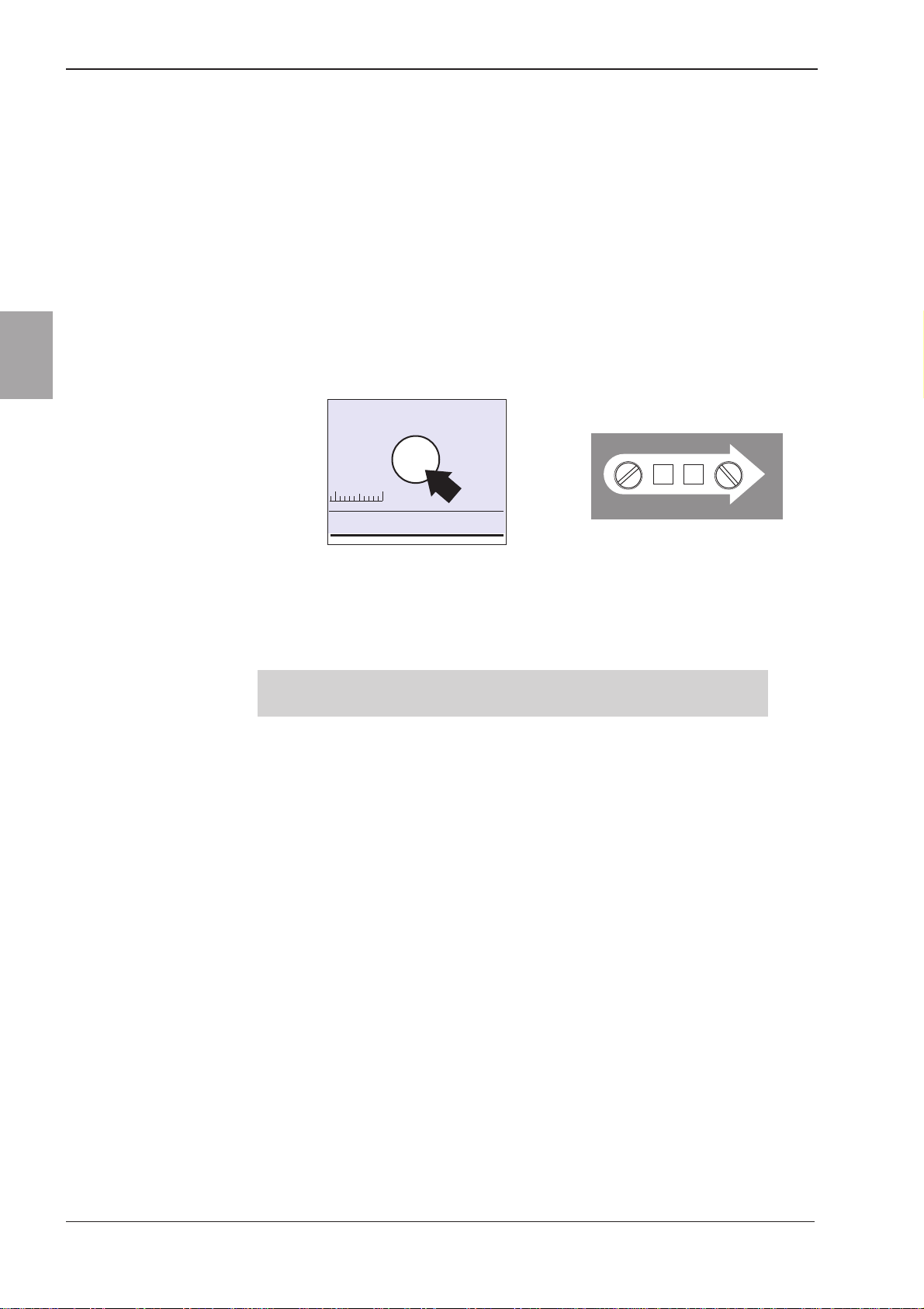
Controls
Patient controls (Figure 1-3) consist of two rotary set rate mm PER
slotted switches, and a START/TEST pushbutton.
START/TEST
50 60mm
GM0418-A
mm PER
9
GM0307-A
0
Figure 1-3 MS16A Controls
Operation
Note: For detailed operating information, refer to the MS16A, MS26
Instruction Manual, part number 0105-0549.
To start an infusion, fit a primed syringe and press the START/TEST
pushbutton.
When held down, the START/TEST pushbutton tests a safety cut-out
circuit. When released, it starts the drive circuit. Once started, the
front panel LED flashes approximately every second.
When the plunger reaches the end of travel (syringe empty) or is
occluded, the driver switches off, the LED stops flashing and an
audible alarm sounds.
If the START/TEST pushbutton is held down for more than 3 seconds,
the alarm sounds, the driver stops and the LED stops flashing.
If required, the driver can be modified to sound a continuous tone
when the driver stops. See Chapter 6, Maintenance for modification
instructions.
For additional protection, the syringe driver can be secured in a
Lockbox.
SM0105-1-6.PMD 2/23/2005, 2:54 PM4
Technical Service Manual Issue 6 (February 2005) 1 — 5
Smiths Medical MS16A Syringe Driver
1
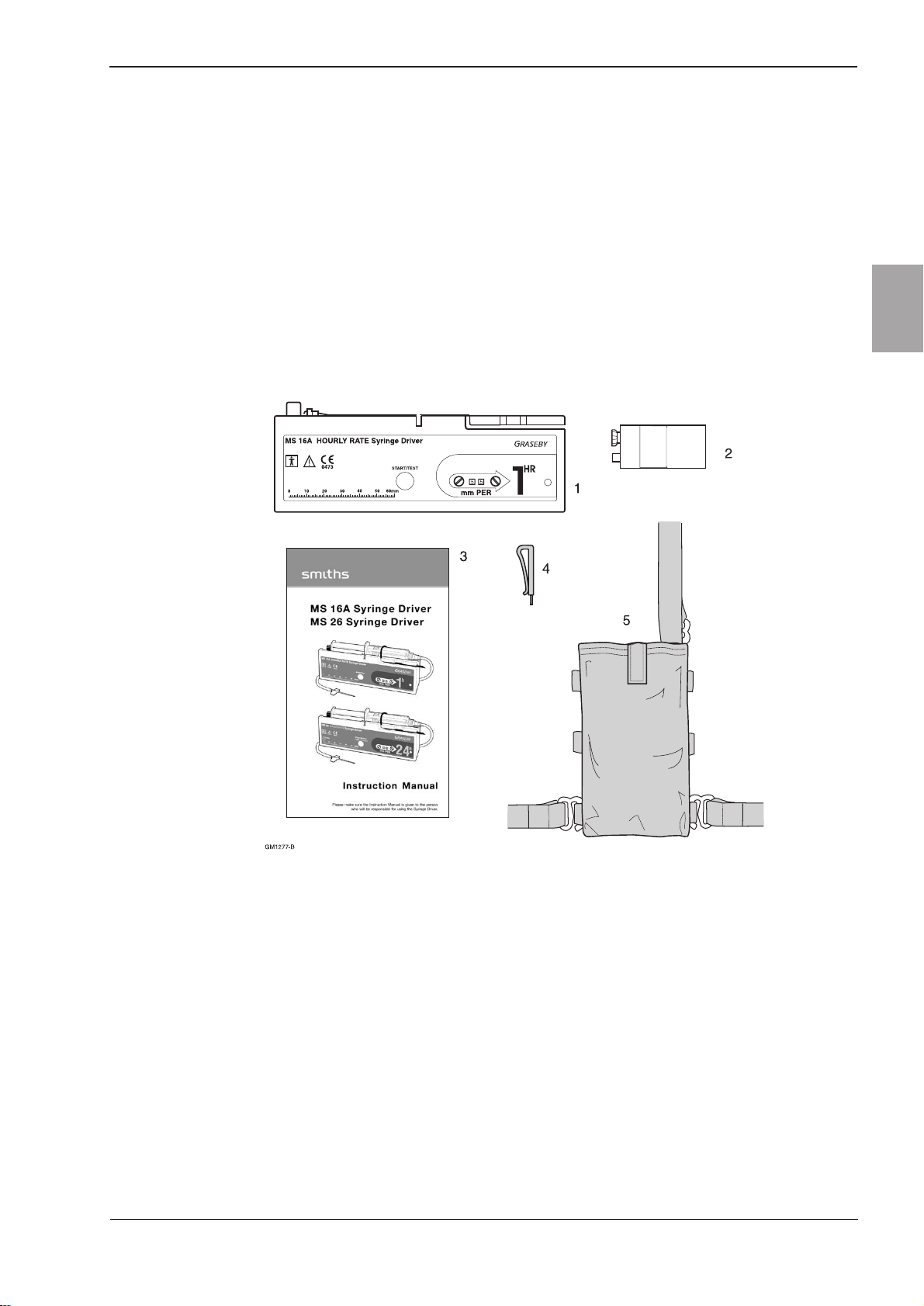
Packed set
The MS16A packed set (part number 0105-0504) is supplied with the
following items:-
1. MS16ASyringe Driver.
2. Battery, type IEC 6LR61.
3. Instruction manual.
4. Rate adjuster.
5. Shoulder holster (not US version).
6. Clear cover (not shown).
Figure 1-4 Package contents
SM0105-1-6.PMD 2/23/2005, 2:54 PM5

Issue 6 (February 2005) Technical Service Manual
Smiths Medical
1 — 6
MS16A Syringe Driver
1
Accessories and consumables
Item Description Part number
100 cm infusion set PVC line with 25 gauge needle. 0105-0029
Subcutaneous BD 10 ml syringe, Tegaderm dressing 0105-0117
infusionpack alcohol wipe, transfer needle,
100 cm infusion set.
Syringe driver Provides a secure base to stand the 0105-0108
non-slip base syringe drive on a flat surface.
Cover Clear rigid plastic to protect the syringe 0105-0529
driver and syringe.
Holster Washable, soft fabric holster with cover 0105-0027
Instruction manual Instructions for use. Guide to subcutaneous 0105-0549
analgesia, technical and performance
specifications.
Rate adjuster Tool to turn slotted rate switches. 0105-0023
Training pack A full package of presentation, instruction TPF-00130
and testing materials.
Lockbox A transparent plastic, lockable security 0105-0640
container (includes two keys). See page 1-3.
SM0105-1-6.PMD 2/23/2005, 2:54 PM6

2
Graseby®MS16A
Syringe Driver
Chapter 2
Specification and Standards
SM0105-2-6.PMD 2/23/2005, 2:55 PM1

Technical Service Manual Issue 6 (February 2005) 2 — 3
Smiths Medical MS16A Syringe Driver
2
Chapter 2 - Specification and Standards
Type:
Syringe driver with motor driven linear actuator, pulsed motion. Internal 9V
alkaline battery power source. Digital electronic rate control.
Automatic switch off when the syringe is empty.
Infusion time:
< 30 min. - 60 hours
Rate range:
Variable delivery rate of 0 - 99 mm/h in steps of 1 mm/h.
Motor operating interval:
420 ÷ rate = seconds
Drive accuracy:
The accuracy of the linear drive mechanism that pushes the syringe plunger
forward: ± 5%
Drive force:
The force the linear drive mechanism that pushes the syringe plunger forward can
produce: >3 Kg
Actuator movement:
0.12 mm every time motor turns.
Actuator stroke:
60 mm available (depends on syringe).
Syringe sizes:
2 ml to 35 ml
The holster supplied will enclose most types of syringe up to 20 ml capacity.
Occlusion pressure:
3 - 5 Kg
Maximum actuator force 50 N (5 Kgf) @ 9 V
Controls:
START/TEST and mm PER rate adjusters (tens and units digit controls).
Alarm:
Audiblefrequency: 3 kHz ± 0.5 kHz (end of travel: occlusion).
Duration: 5 - 20 secs.
Volume: Audible at 1m with normal or corrected hearing
SM0105-2-6.PMD 2/23/2005, 2:55 PM3

Issue 6 (February 2005) Technical Service Manual
Smiths Medical
2 — 4
MS16A Syringe Driver
2
Indicator:
Low battery level: 7.0 V to 5.5 V (LED stops flashing)
Flashperiod:1.05 secs ± 2%
Yellow solid state LED
Green solid state LED (US)
Battery type:
PP3 size. 9 V, primary alkaline, IEC 6LR61 (or 6LF22) type.
(Duracell MN1604 recommended)
Battery life:
50 full deliveries depending on the operating conditions and battery condition.
Automatic switch off at end of plunger travel.
Accuracy of delivery:
The rate of the actuator is accurate to within plus or minus 5% of the rate set on
the rotary switches.
Dimensions (without syringe):
Height: 53.0 ± 0.5 mm
Width: 166.0 ± 1.0 mm
Depth: 23.0 ± 1.0 mm
Weight (including battery):
190 gm.
Operating conditions:
+10° C to +40° C. 30% to 75% RH (non-condensing).
700 hPa to 1060 hPa
Transport and storage conditions:
-40° C to +70° C. 10% to 100% RH (non-condensing).
500 hPa to 1060 hPa
Materials:
Case and battery cover - ABS RTA50 injection moulding.
Labels - 125 micron fine matt Lexan.
Other materials - nitrile rubber, small plastic parts -Acetal (25% glass filled
Kemetal) and PA-GF (glass-filled nylon).
Metal parts - stainless steel, mild steel.
Circuit board - epoxy glass fabric.
Holster - elasticated soft-backed fabric.
Note:All materials used in this product are latex free.
SM0105-2-6.PMD 2/23/2005, 2:55 PM4
Table of contents
Other Smiths Medical Equipment manuals

Popular Medical Equipment manuals by other brands

Otto Bock
Otto Bock E-MAG Active 17B203-L Instructions for use

ROHO
ROHO ADAPTOR PAD Operation manual

BeautyRelax
BeautyRelax BR-2610 user manual

Pressalit
Pressalit MCT 3 Operation and maintenance manual

MPS
MPS M.C. Rexx QD2000 Series Use Care and Service Parts Manual

Hospira
Hospira Plum 360 Technical & service manual


