SMT 600REY User manual
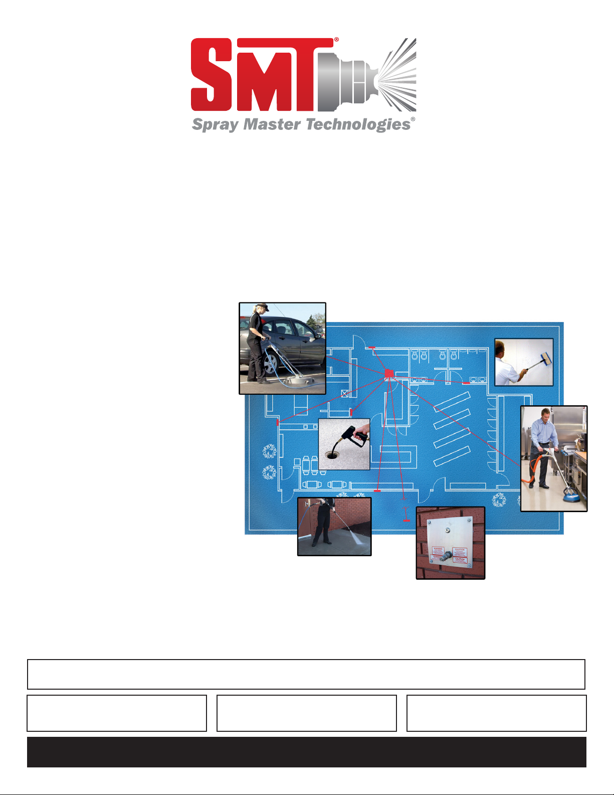
Express Service Manual
Central Systems
600REY, 600WCY, 2000REY
You have just purchased the best
spray washer on the market today.
It incorporates the very latest in
technological advances. To assure you
the best and safest performance as
well as longest equipment life, please
read the enclosed information.
After reading the material in this
manual, should you have a service
problem or need help, please call our
toll free number 1-800-548-3373 or
(479) 636-5776.
TERMS: All parts will be shipped with
check in advance or C.O.D. Commercial
accounts are allowed 15 day terms
from date on invoice with approved
credit.
FREIGHT: All freight will be paid by
the customer. Special consideration
will be given to items under warranty
coverage.
NOTE: Specications found in this manual subject to change without notice.
FOR COMMERCIAL USE ONLY
IMPORTANT DOCUMENT - DO NOT DISCARD
Date PurchasedSerial NumberModel Number
SprayMasterTech.com

2
SMT WARRANTY – LIMITED Eective June 23, 2017
Parts – Spray Master Technologies warrants parts for wall mounted and rack mounted 600 series and 2000 series units to be free
from defects in material or workmanship for a period of 2 years from the date of shipment from the factory excluding items listed
below.
Spray Master Technologies warrants parts for all other units (wall mounted 1100 series and all portable units) to be free from
defects in material or workmanship for a period of 1 year from the date of shipment from the factory excluding items listed below.
This warranty is limited to the original purchaser and includes repairing or replacing parts which manufacturer’s investigation
shows to be defective at the time of shipment from the factory. All parts subject to this warranty shall be returned F.O.B. Spray
Master Technologies, Rogers, Arkansas for examination, repair, or replacement.
Excluded Items – The follow items are excluded: spray guns, wands, hoses, nozzles, Hummer Jet Sr & Jr, casters and handles. These
items are covered by the above warranty for 90 days from the date of purchase for defects in materials or workmanship.
Labor and Travel – Labor and travel to repair or replace defective parts shall be covered for a period of 1 year from date of
shipment (90 days on the excluded items).
Items Voiding Warranty – The following voids all warranty claims on Spray Master Technologies products: Accidental breakage;
abuse; misuse; failures caused by incorrect installation (if not factory installed); failure to correctly wire the system at the electrical
source; chemical or mineral buildup in the pumps and water lines caused by untreated or unltered tap, hard, or recaptured
water; excessive hot water temperatures exceeding 120° Fahrenheit (49° Celsius); using bleach as an injected chemical; injecting
harsh or corrosive chemicals in non-compatible equipment.
www.spraymastertech.com
Phone: (479) 636-5776 • Fax: (479) 636-3245 • 115 E. Linden • Rogers, Arkansas 72756 USA
SMT-WARRANTY-Rev 1-170623-EN Specications are subject to change without notice Printed in the U.S.A.
Returned Goods Policy
Any item returned for warranty consideration or for credit must
have a RETURN AUTHORIZATION NUMBER. Call our Customer
Service Department and discuss the nature of your request.
Please note that all items returned must be returned F.O.B. Rogers,
Arkansas. No collect or C.O.D. shipments will be accepted unless
prior arrangements with our Customer Service Department have
been made. A restocking fee may be applied to items for credit that
are not under warranty. To reach our Customer Service Department
call (800) 548-3373 or (479) 636-5776, or write to Spray Master
Technologies, 115 E. Linden Street, Rogers, Arkansas 72756.
Receiving
Damage: Report any damage to the shipping carton or contents
to the freight carrier. File a claim with the carrier within 10 days if
damage is evident. The manufacturer is not responsible for damage
to the equipment caused by the freight carrier.
Package Contents: Carefully check the contents of the shipping
cartons to ensure the contents agree with the packing list. If items
are missing or if you have any questions, please call our customer
service department at (800) 548-3373 or (479) 636-5776.
Table of Contents
Receiving 2
Returned Goods Policy 2
Warranty 2
Service 3
Service Requirements 3
Express Service Program 3
Model Identification 3
Theory of Operation - Mechanical 4
Theory of Operation - Electrical 5-8
Wiring Diagram 7-8
Central System Diagnostic Chart 9-11
600REY / WCY Parts Breakdown / List 12
2000REY Parts Breakdown / List 13
Recess Mount Remote Parts Breakdown / List 14
Surface Remote Parts Breakdown / List 15
Spray Gun Parts Breakdown / List 15
Hummer Jet Jr. Parts Breakdown / List 16
Hummer Jet Sr. Parts Breakdown / List 17
SMT-300HDR Parts Breakdown / List 18

3
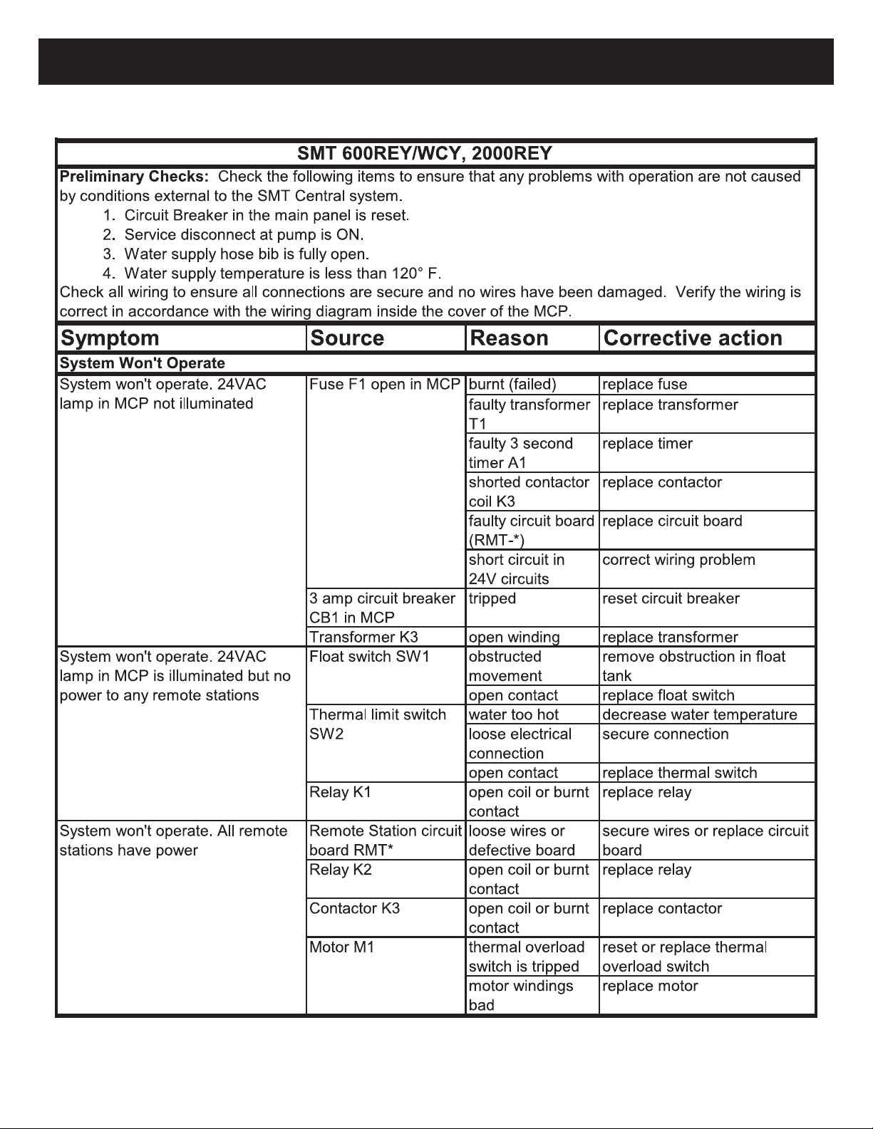
If a problem occurs, please refer to the
“Diagnostic and Maintenance Chart” in the
product Service Manual. Also, refer to the
CAT Pumps and General Pumps Service
Manuals provided with your system. If the
problem is not resolved, then please call
our toll free customer service number:
1-800-548-3373 or (479) 636-5776
The complete model number located on the serial
number label identies the series, type, and operating
specications of the system.
Service Requirements
Water:
• Flow: minimum 5 GPM at 30 PSI (3/4”
hose bib connection)
• Temperature: 40° to 120° F (maximum
120° F)
Electric:
• SMT 600 Series:
208-230V/20Amp (single phase) Dedi-
cated Circuit with Ground Fault breaker.
(NEMA 6-15R) Rated for wet location at
the unit.
• SMT 2000 Series:
208-230V/30Amp (single phase) dedi-
cated circuit with ground fault breaker.
(Nema L630R) rated for wet locations at
the unit.
• International:
See Serial Number Plate on machine
Model IdenticationService
Express Service Program
If you have a problem, we can solve it QUICKLY and EFFICIENTLY.
Your Spray Master Technologies pressure cleaning system has
been designed for rapid and easy repairs. Some, you can do,
others we will do.
With the“EXPRESS SERVICE” program, your machine has been
divided into six major component groups. These groups consist of:
Group #1: Pump, Unloader, Injector, In/out hoses
Group #2: Motor, Switch, and Cord Set
Group #3: Float Tank Assembly
Group #4: High Pressure Hose
Group #5: Spray Gun Assembly
Group #6: Accessories and Miscellaneous Parts
Like circuit boards on a computer, these groups can be
exchanged as a complete unit. The advantage is your savings in
time and money.
With a toll free call to experienced service technicians at Spray
Master Technologies, the problem can usually be diagnosed to
one of the six component groups by answering a few questions.
The person doing the parts replacement doesn’t need to have
any equipment knowledge. He/she need only be able to loosen
and tighten a few bolts. The“Express Service” exchange program
eliminates having an inexperienced person trying to repair a
complicated part.
If you do your own“GROUP” exchange, you won’t be paying for
those high labor rates and expensive service calls. With a few
basic tools, the defective component group can be removed and
replaced or sent to the factory for repair by a qualied technician
with minimum downtime. To further expedite the repair, either
you or your dealer can stock spare components“groups”. However,
with express mail services, rarely does it take more than 48 hours to
receive a component. This is usually faster and less expensive than
many service companies can make a service call.
The enclosed information shows all components groups and
accessories. Our trained personnel are ready to help. If you need
service, try our “EXPRESS SERVICE” plan. It will save you time and
money.
Model #: SMT 600 RE Y 22 20 04 0850
Series
SMT 600
SMT 2000
Type
-RE = Rack Mount System
-WC = Wall Mount System
Chemical Injection
Y = Before the Pump
X = After Pump
Pump Flow Rate (gallons per minute)
22 = 2.2 GPM 36 = 3.6 GPM
29 = 2.9 GPM 40 = 4.0 GPM
Motor Horsepower
20 = 2 HP Motor5 0 = 5 HP Motor
Nozzle Size
04 = #4 Nozzle 05= # 5.0 75 = # 7.5 Nozzle0 8 = #8 Nozzle
Max Operating Pressure
0850 = 850 PSI 1100 = 1100 PSI2 000 = 2000 PSI
4
General Principle of Pressure Washers.
Pressure in Spray Master Technologies and most other pressure
washers is produced by forcing a xed gallons per minute
(GPM) volume of water through an orice. The xed volume of
water is provided by a positive displacement pump, which will
produce a specic GPM of water ow regardless of the operating
pressure. The orice is a part of the nozzle on the end of the
Theory of Operation - Mechanical
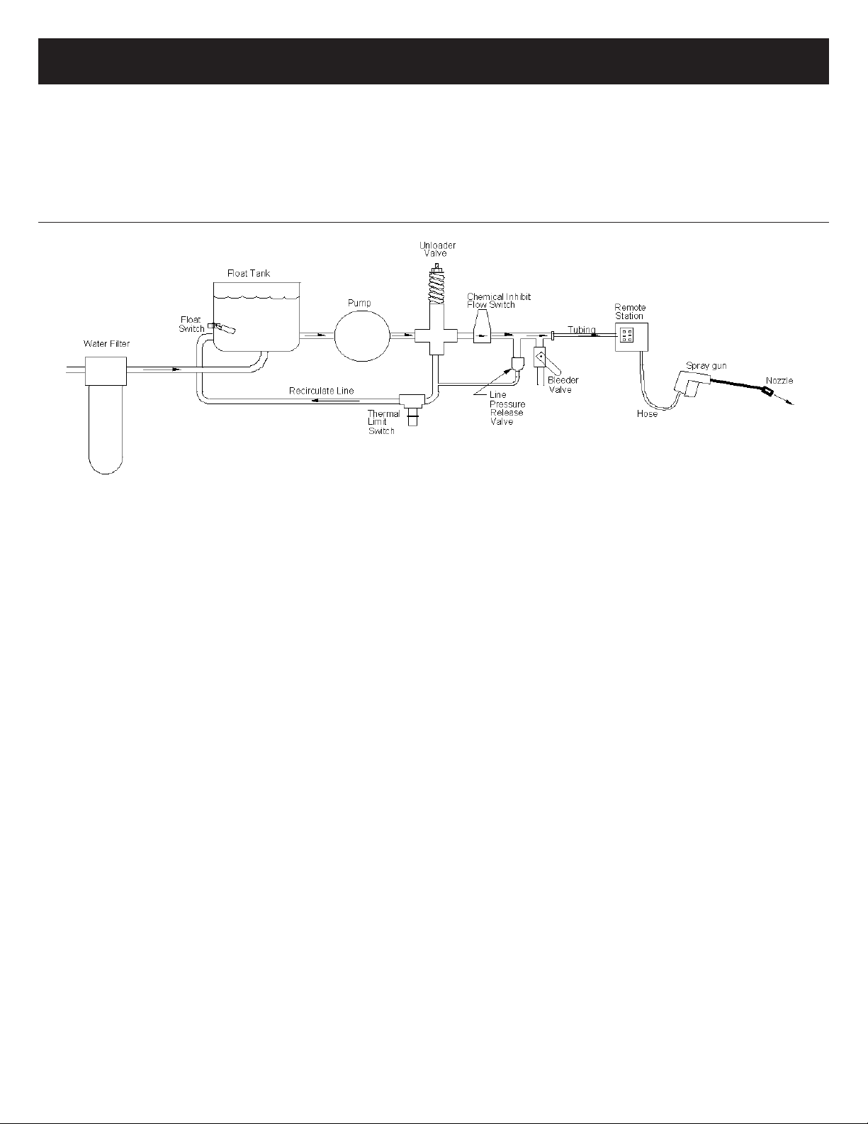
Figure 1. Simplied SMT Central Pressure Cleaning System
The water supply source to the system must provide a minimum
ow of ve gallons per minute at 30 PSI, and should be ltered
through a high quality lter to eliminate contaminates that will
cause wear and shorten the life of the pump. The output from the
lter enters the oat tank through one or two oat valves within
the tank. The oat tank maintains a minimum water source for
the pump and is monitored by the oat switch. If the water level
falls below the oat switch, the system is disabled to prevent
damage that would occur from running the pump dry.
When the pump is in operation, it draws water from the oat
tank and pumps it out to the unloader assembly. The unloader
assembly directs the water through the system to the spray gun
if the spray gun is open, or it diverts the water back to the oat
tank, through the re-circulate path, if the spray gun is closed. In
addition, the unloader is used to set the maximum operating
pressure of the system.
From the high-pressure output of the unloader, the water ows
through the chemical inhibit ow-switch, past the bleeder valve
assembly to the interconnecting high-pressure tubing and out to
all the remote stations. The pump can service up to ten remote
stations. Each remote station is equipped with a quick-connect
port for connection of a high-pressure hose.
spray gun. The volume of water and the orice size can be varied,
resulting in a corresponding change in the operating pressure
of the system. The following paragraphs explain the function of
system components and ow sequence in SMT pressure cleaning
systems. This brief theory of operation will provide a service tech
with information necessary to quickly diagnose and correct any
malfunction of the system.
Water Flow
Refer to Figure 1, Simplied SMT Central Pressure Cleaning
System, for the following discussion. The key plumbing
components of a basic SMT Central Pressure Wash System
consists of 1) water lter, 2) water supply oat tank, 3) oat
switch, 4) pump, 5) unloader valve, 6) chemical inhibit ow
switch, 7) bleeder valve, 8) interconnecting hi-pressure tubing, 9)
remote stations, 10) hi-pressure hose, 11) spray gun/nozzle, 12)
line pressure release valve and 13) thermal limit switch.
From the remote station, the water ows through the hose to
the spray gun. The water passes through the spray gun when
the gun-trigger is activated and ows to the nozzle at the end of
the lance. As the water is forced through the orice in the nozzle,
pressure builds within the system. The size of the orice in the
nozzle determines the maximum pressure that can be achieved
with the ow rate provided by the pump. The smaller the orice,
the higher the pressure. Most SMT systems are equipped with a
dual nozzle selector and two nozzles. The nozzle with the small
orice will produce high pressure, while the nozzle with the large
orice produces low pressure.
Note: Selecting the correct nozzle size
for the system is critical to the correct
operation and cleaning eectiveness.
A nozzle with too small an orice will
result in less water ow and reduced
cleaning eectiveness and may result
in too high pressure, overloading the
motor. A nozzle too large will result in
lower pressure and reduced cleaning
eectiveness.
During operation, when the spray gun trigger is released,
pressure builds in the system until it overcomes the tension on
the unloader spring and activates the unloader assembly. When
the unloader assembly is activated, it locks pressure into the
output line to the spray gun and redirects the ow of water, at
low pressure, through the recirculate line back to the system oat
tank. Recirculation will continue until the line pressure is reduced
by reactivating the trigger on the spray gun. This unloading
feature prolongs the life of the pump and motor by removing the
strain on the pump and motor during periods when the spray
gun is inactive.
5
Theory of Operation - Electrical
Electrical Requirements
The electrical requirements for the SMT Central Pressure Cleaning
system depends on the SMT model installed. Regardless of model,
all central systems must be powered by a dedicated circuit with a
Ground Fault Circuit Interrupter (GFCI) breaker in the main breaker
panel. Electrical service requirements are:
2000REY: (Nema L630R) 208/230 Volt, 30 Amp rated for wet locations
at the unit.
600REY/WCY: (NEMA 6-15R) 208/230 Volt, 20 Amp Rated for wet
location at the unit.
Line voltage to the system is supplied from the dedicated outlet
through power cord into the SMT Master Control Panel (MCP) to
the input side of contactor K3.
Motor Drive Circuit
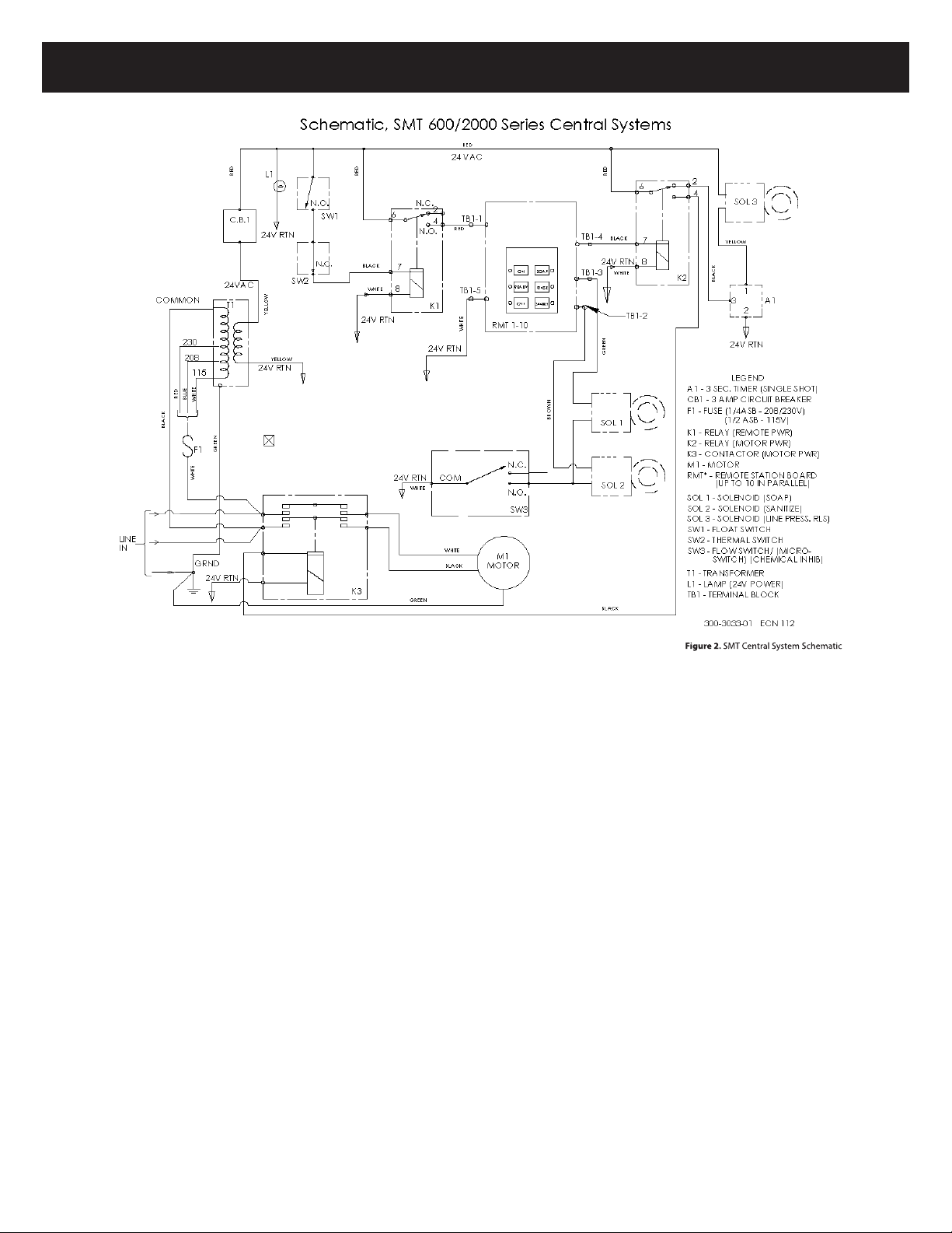
Refer to Figures 2 and 4 (schematic and wiring diagram of the SMT
electrical circuits). When contactor K3 is energized by the control
circuit, the line voltage is applied through the contactor to the
motor. The motor starts up, drives the pump and produces water
ow.
Control Circuits
Control circuits within SMT central systems are 24 Volt AC low
voltage. The control circuits include the 24V AC power circuit,
water condition sensors circuit, remote stations circuit, motor
control circuit, chemical control circuits and the line pressure
release circuit.
24V AC power circuit provides low voltage AC for all control
circuits. Line voltage to the system is picked o of the contactor
line terminals and applied through fuse (FI) to the multi-tap input
of the 24V transformer (T1). F1 requires a ¼ amp slow-blow fuse
for 208 and 230 volt inputs. Voltage is applied to Transformer (T1)
through one of three leads of the primary winding. The multi-tap
primary leads permit system operation on 208 or 230 volts AC.
The 24V output is routed through 3 amp circuit breaker (CB1)
to the 24V AC Power indicator (LI) and the rest of the control
circuits. Current ow through all circuits returns to the transformer
through the 24V AC return line. The 24V AC is connected to Float
Switch (SW1), Remote Station Power Relay (K1), Motor Drive Relay
(K2), and to the Line Pressure Release Solenoid (SOL 3).
Water condition sensor circuits provide protection to the pump
when adverse water conditions exist. The sensors will remove
power from the remote stations when the water supply level is
too low or water temperature exceeds 120° F. Float Switch (SW1)
is closed when the water level in the oat tank is above the
minimum operating level for the pump, completing the circuit
through Thermal Limit Switch (SW2) which will energize Relay (K1)
and apply power to all Remote Stations (RMT-*). Thermal Limit
Switch (SW2) is normally closed. When water temperature within
the system exceeds 120°F, Thermal Limit Switch (SW2) will open
and remove power from the remote stations.
(continued on next page)
6
Theory of Operation - Electrical (cont.)
Remote station control circuits facilitate remote operation of
the pump and consists of up to ten remote stations (TB1 – TB10),
ve conductor shielded cable and 5-pole Terminal Block (TB1). All
signals to and from the remote stations enter and exit the Master
Control Panel through terminal block (TB1). Signal lines to/from
the remote are:
Red wire – 24V AC power (out to remote station)
White wire – 24V AC return (out to remote station)
Black wire – 24V AC motor control signal (in from remote
station)
Green wire – 24V AC soap control signal (in from remote
station)
Brown wire – 24V AC sanitizer control signal (in from
remote station)
All remote stations are connected in parallel through the 5
conductor shielded cable. Each remote is spliced into the main
trunk of the control cable by color matching and connecting the
wires at each splice.
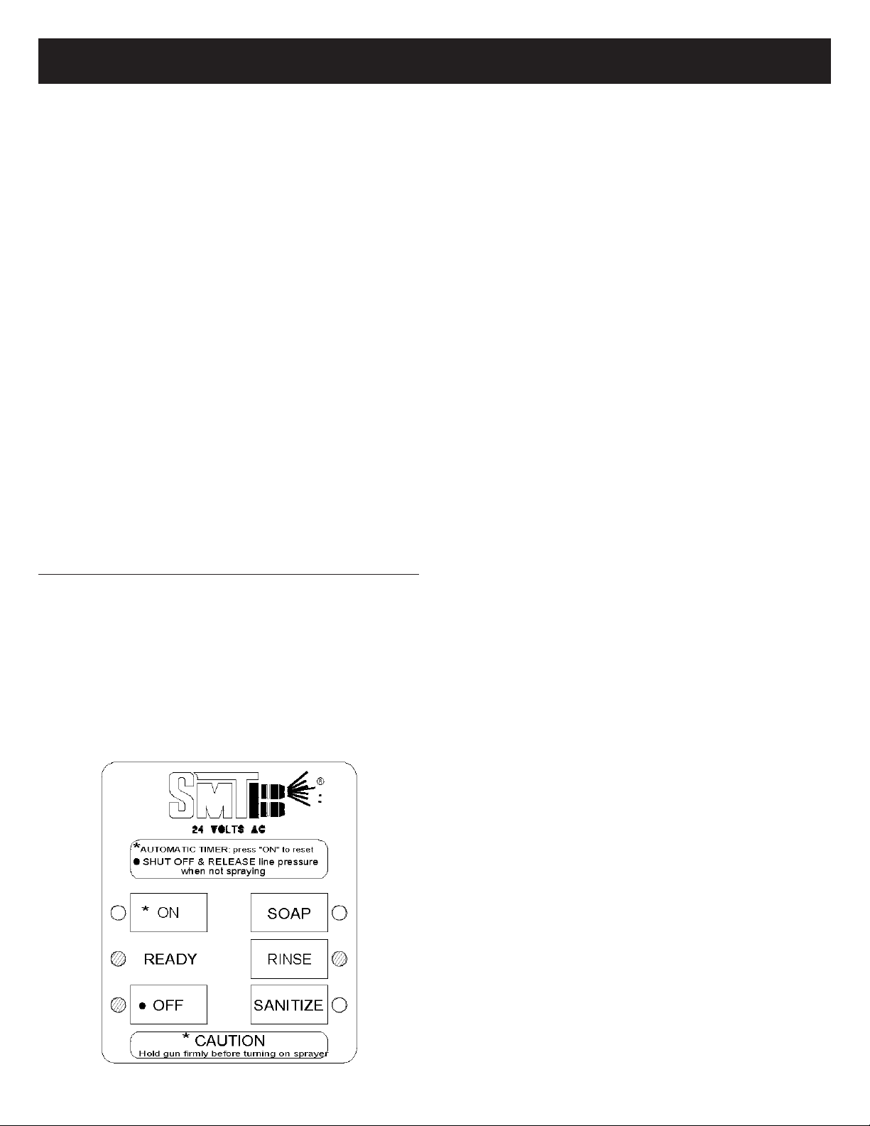
Refer to Figure 3, Remote Station Control Panel. When power
is initially applied to each remote station, the Remote Station
Control Panel will power-up in the “READY” state with the
indications and outputs as shown.
Touch pad Control Lead/ Output
Button Lamp Signal Wire Signal
ON o Motor control Black 0 volt
READY on n/a
OFF on n/a
SOAP o Soap control Green 0 volt
RINSE on n/a
SANITIZE o Sanitizer control Brown 0 volt
The remote stations will remain in the “READY” state until it is
operated with the touch-pad buttons on its control panel or
another remote is operated. When the “ON”button is pressed,
the “ON”lamp illuminates, the“READY” lamp and “OFF”lamp will
extinguish, and 24V AC will be present at the motor control signal
output (black wire). The motor control output must be active for
either the soap or sanitize controls to be active regardless of what
the soap or sanitize lamps may indicate.
Note: The motor control lead (black) is both an output and input
for the remote station. When any remote station is turned to “ON”
the 24V AC out from that remote station is applied to the motor
control circuit and to the Motor Control lead (black) of all other
remote stations. The 24V AC applied by the active remote station
to all other remote stations becomes an “inhibit” input signal. The
inhibit signal will force the remotes out of the “READY” state and
disable them.
The Motor control circuit is the signal control path from the
remote station to turn on the pump. When the ON button is
pressed on the remote station, the motor control signal (24V AC) is
sent through the 5-conductor control cable black wire to Terminal
Block (TB1) pin 4 in the Master Control Panel. From TB1-4, 24V
AC is sent to the coil of Motor Control Relay (K2). When K2 closes,
24VAC power is applied through its contacts to the coil of Motor
Contactor (K3) to turn on the pump motor (M1).
Chemical Control Circuits are driven by the remote station
circuit boards and control the ow of chemical in the system.
The chemical control circuits become functional only when the
pump is ON. While the pump is running, the operator may select
either Soap or Sanitizer using the Remote Station Control Panel.
The Soap circuitry and the Sanitize circuitry operation is identical.
When the operator selects Soap, the remote station Control Panel
will send 24V AC out the green lead through the 5-conductor
cable to Terminal Block (TB1) pin 3 of the Master Control Panel.
From TB1-3 the 24V AC is routed to the coil of Soap Solenoid
(SOL 1). SOL1 is connected in series with Chemical Inhibit Switch
(SW3) to the 24V AC return. If SW3 is closed, indicating that water
is owing out to the spray gun, the Solenoid is activated and
chemical is injected into the owing water. If the spray gun is
closed and the water is re-circulated to the oat tank rather than
through the ow switch, the ow switch SW3 is open and the
chemical solenoids are disabled. Only one chemical control circuit
can be enabled at a time.
The Line Pressure Release Circuit controls the Line Pressure
Release Valve (SOL3) to automatically release pressure from the
system, upon turning the pump o. The line pressure release
circuit is driven by the normally closed output of Motor Control
Relay (K2). When the pump is turned “OFF” by the control panel,
Relay K2 is de-energized, sending 24V AC from the relay to solid
state 3-Second Timer (A1) pin 3. Upon receiving the 24V AC signal,
A1 energizes SOL3 for three seconds to open the solenoid and
release any pressure that may remain in the pressurized output
lines. SOL3 is de-energized and closes the Line Pressure Release
Valve at the end of three seconds, or immediately upon turning
the pump back “ON
Figure 3. SMT Remote Station Panel

7
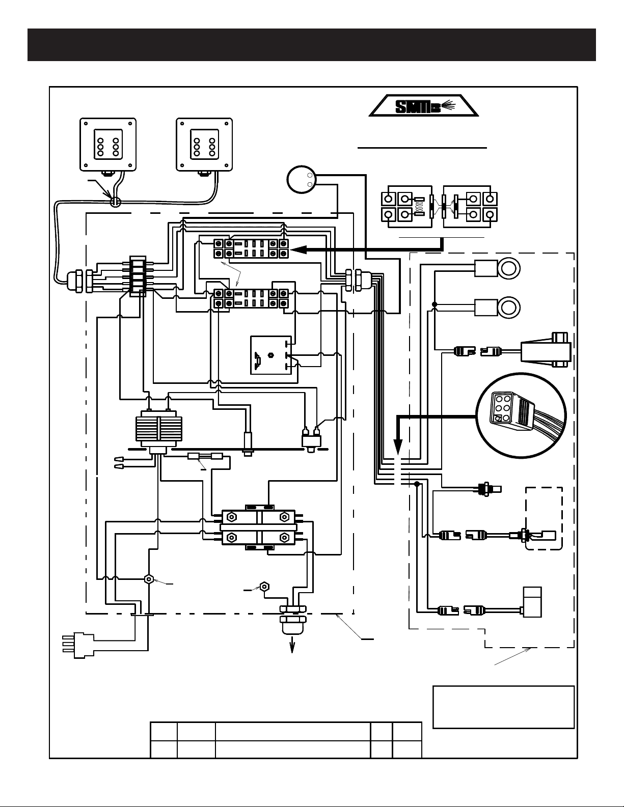
Figure 4. SMT Central System Wiring Diagram
Theory of Operation - Electrical (cont.) Wiring Diagram
1
2
34
56
3-AMP
MANUAL
RESET
BREAKER
LINE (L1)
LINE (L2) OR NEUTRAL
GREEN
GREEN
WHITE
BLACK
CONTACTOR
LEAD (TO MOTOR)
WARNING:
GFCI REQUIRED IN SUPPLY CIRCUIT.
ALL CONNECTIONS MUST BE RATED
FOR WET LOCATIONS, MUST
COM-
PLY WITH ELECTRICAL CODES.
WIRING DIAGRAM, CENTRAL SYSTEMS
ROGERS,ARK. 72756
SPRAY MASTER TECHNOLOGIES
MASTER CONTROL PANEL
30 AMP
CAUTION: HIGH VOLTAGE
WARNING: DISCONNECT POWER BEFORE SERVICING
208, 230, VOLT SYSTEMS
N.C.
GROUND
LUG
208/230 VAC
200-1025
1
2
34
56
LUG
RED
BRO WN
GREEN
BLACK
WHITE
BRO WN
RED
GREEN
BLACK
WHITE
WHITE
BLACK
BLACK
BLACK
RELAY,
TIME DELAY
RED
RED
YELLOW
BLACK
BLACK
FUSE,
1/4 AMP, SB
N.O.
N.C.
RED
300-2849
300-2887 SOCKET, WITH
300-2888 RELAY, SPDT
5 POLE
BARRIER STRIP
300-2837
REMOTE STATION BOX
24 VOLT, 5/6 CONDUCTOR SHIELDED CABLE
REMOTE STATION BOX
SPLICE -
ISOLATE COLORS
TO COLORS:
RED TO RED ETC.
24 VAC 24 VAC
GREEN
YELLOW
COMMON
BLUE WIRE
NOT USED
AC+
AC-
LOAD
YELLOW
WHITE
WHITE
300-2885
GROUND
(OPTIONAL 20 AMP
FOR SMT 600)
WHITE
SEE VOLTAGE
WIRING LABLE ON
TRANSFORMER
N.C.
5
6
1
3
4
2
N.C.
1
2
3
MULTI-
CONNECTOR
WIRE ROUTING
FROM CONNECTOR
300-2888/300-2887 SOCKET/RELAY DETAIL
6
5
4
BROWN
WHITE
WHITE
GREEN
BLACK
BLACK
SALES & SERVICE - 1-800-548-3373
TRANSFORMER
300-2861
300-2482
RED
BLACK OR WHITE
LED (24V)
N.O.
33
111
77
WHITE
RMT-1 RMT-2
TB1
K1
K2
F1
L1
SOL 3
SW1
SW2
M1
K3
T1
CB1
SW3
SOL 1
SOL 2
A1
1
2
3
4
5
HOUR
ME T ER
(OPTIONAL)
+
-
BLACK
WHITE
12
Add Powr Cord to Master Control Panel
Tom
6/28/18
SMT 600REY,600WCY
SHIEL DE D DRAIN WIRE
GREEN
Pump Assembly
Incoming Power Cord
208V / 15A Nema 6-15R
SOLENOID
FLOAT TANK
SWITCH
THERMAL SWITCH
SOLENOID
SOAP
SANITIZE
PRESSURE RELIEF
SOLENOID
SWITCH
FLOW
CHG
ECN#
DESCRIPTION OF CHG
DATE
BY
8
Figure 5. SMT Central System Wiring Diagram
Theory of Operation - Electrical (cont.) Wiring Diagram
1
2
34
56
3-AMP
MANUAL
RESET
BREAKER
LINE (L1)
LINE (L2) OR NEUTRAL
GREEN
GREEN
WHITE
BLACK
CONTACTOR
LEAD (TO MOTOR)
WARNING:
GFCI REQUIRED IN SUPPLY CIRCUIT.
ALL CONNECTIONS MUST BE RATED
FOR WET LOCATIONS, MUST
COM-
PLY WITH ELECTRICAL CODES.
WIRING DIAGRAM, CENTRAL SYSTEMS
ROGERS,ARK. 72756
SPRAY MASTER TECHNOLOGIES
MASTER CONTROL PANEL
30 AMP
CAUTION: HIGH VOLTAGE
WARNING: DISCONNECT POWER BEFORE SERVICING
208, 230, VOLT SYSTEMS
N.C.
GROUND
LUG
208/230 VAC
200-1025
1
2
34
56
LUG
RED
BRO WN
GREEN
BLACK
WHITE
BRO WN
RED
GREEN
BLACK
WHITE
WHITE
BLACK
BLACK
BLACK
RELAY,
TIME DELAY
RED
RED
YELLOW
BLACK
BLACK
FUSE,
1/4 AMP, SB
N.O.
N.C.
RED
300-2849
300-2887 SOCKET, WITH
300-2888 RELAY, SPDT
5 POLE
BARRIER STRIP
300-2837
REMOTE STATION BOX
24 VOLT, 5/6 CONDUCTOR SHIELDED CABLE
REMOTE STATION BOX
SPLICE -
ISOLATE COLORS
TO COLORS:
RED TO RED ETC.
24 VAC 24 VAC
GREEN
YELLOW
COMMON
BLUE WIRE
NOT USED
AC+
AC-
LOAD
YELLOW
WHITE
WHITE
300-2885
GROUND
(OPTIONAL 20 AMP
FOR SMT 600)
WHITE
SEE VOLTAGE
WIRING LABLE ON
TRANSFORMER
N.C.
5
6
1
3
4
2
N.C.
1
2
3
MULTI-
CONNECTOR
WIRE ROUTING
FROM CONNECTOR
300-2888/300-2887 SOCKET/RELAY DETAIL
6
5
4
BROWN
WHITE
WHITE
GREEN
BLACK
BLACK
SALES & SERVICE - 1-800-548-3373
TRANSFORMER
300-2861
300-2482
RED
BLACK OR WHITE
LED (24V)
N.O.
33
111
77
WHITE
RMT-1 RMT-2
TB1
K1
K2
F1
L1
SOL 3
SW1
SW2
M1
K3
T1
CB1
SW3
SOL 1
SOL 2
A1
1
2
3
4
5
HOUR
ME T ER
(OPTIONAL)
+
-
BLACK
WHITE
12
Add Powr Cord to Master Control Panel
Tom
6/28/18
SMT 2000REY
SHIEL DE D DRAIN WIRE
GREEN
Pump Assembly
Incoming Power Cord
208V-230V / 30A Nema L630R
SOLENOID
FLOAT TANK
SWITCH
THERMAL SWITCH
SOLENOID
SOAP
SANITIZE
PRESSURE RELIEF
SOLENOID
SWITCH
FLOW
CHG
ECN#
DESCRIPTION OF CHG
DATE
BY
9
(continued on next page)
Central System Diagnostic Chart
10
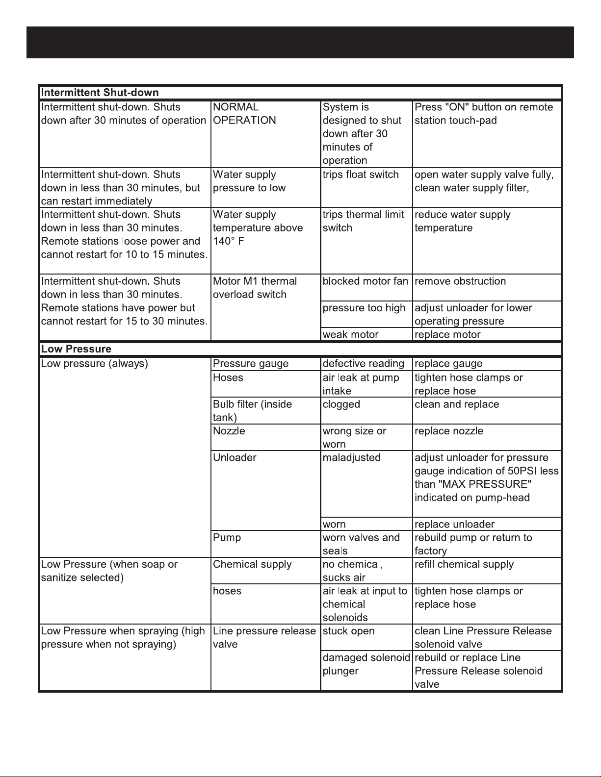
Central System Diagnostic Chart (cont.)
(continued on next page)
11
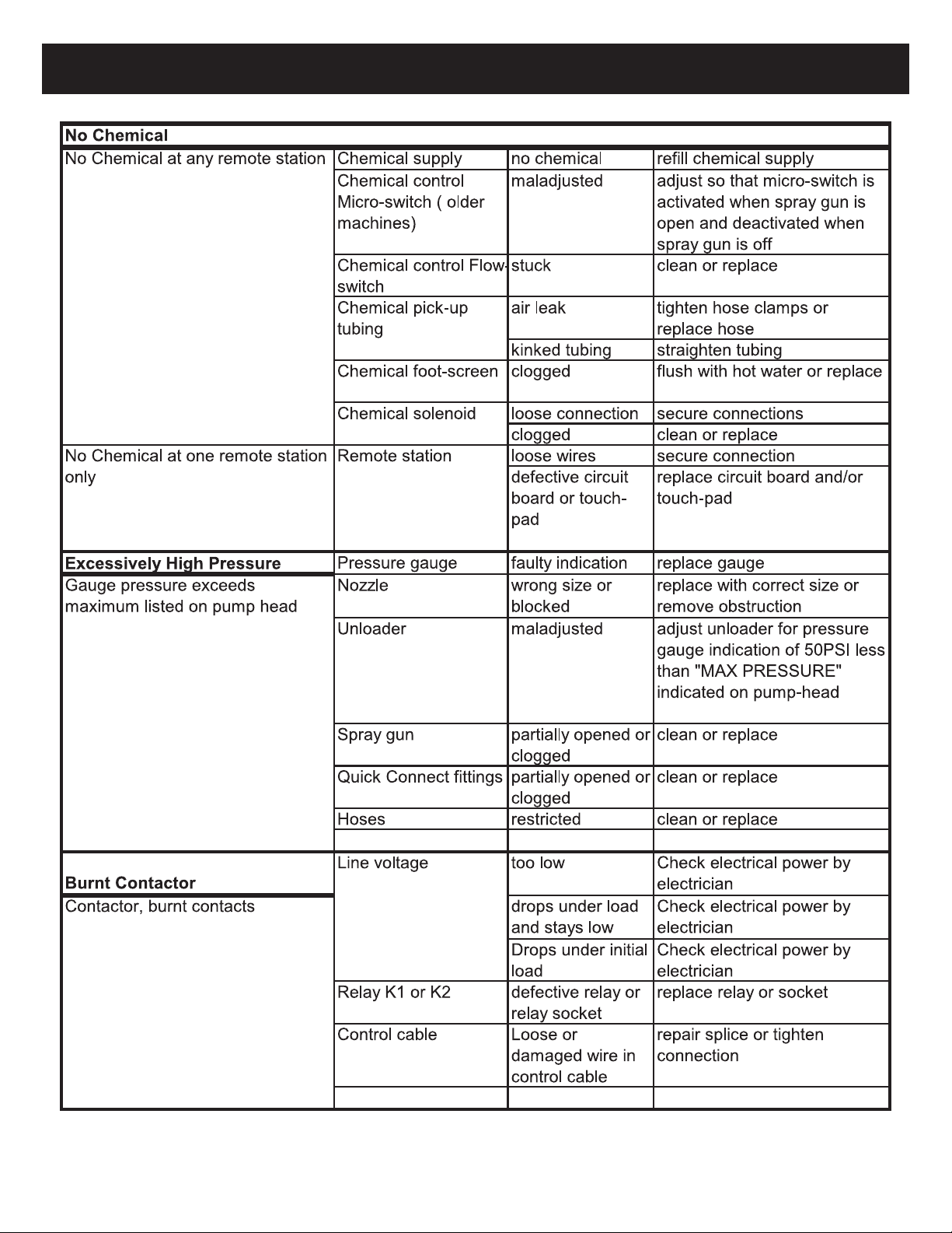
Central System Diagnostic Chart (cont.)
12
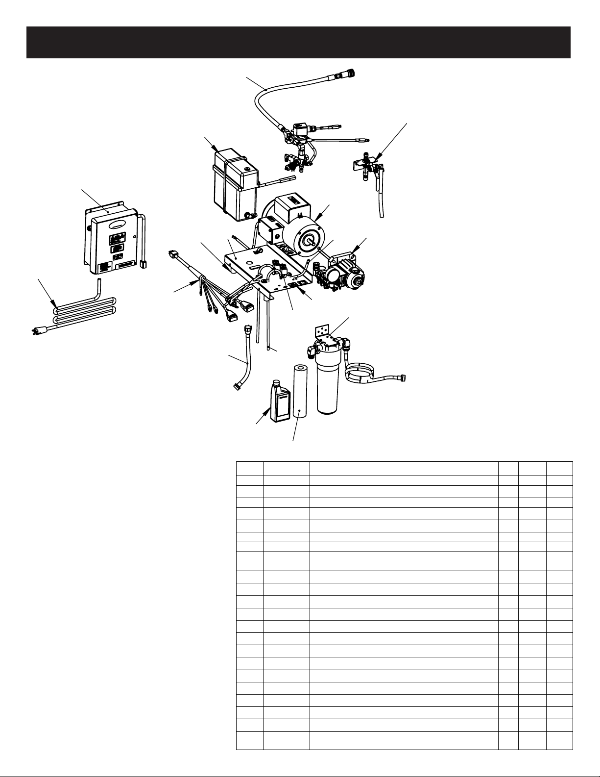
600REY / WCY Parts Breakdown / List
Figure 6.
600REY/WCY Exploded View
7
8
18
1
6
4
511
12
14
13
15
16
10
9
2
3
17
Item 5. 300-0838 is the
item changing for ETL.
ITEM
PART No.
DESCRIPTION
QTY.
Length
U/M
1
300-1733
Unloader, 600REY/WCY w/Flow Switch
1
Ea
Unloader Assy, 600REY/WCY, Hi-Temp
2
300-2756
Frame, Plt, 600W, SS, 600 Wlmnt Series
1
Ea
3
300-0494
Hardware: 600REY, Working Assy, Phan
1
Ea
4
300-1885
Panel Master Control, 600 Control Sys
1
Ea
5
300-0838
Pwr Cord, 6', 240V, 15A, Nema 6-15
1
Ea
6
300-0403
Tank, 600WD/REY/WCY w/Float Switch
1
Ea
7
300-0041
Motor Assy, 600REY/WCY, 208-230V, Prwrd
1
Ea
300-0040
Motor Assy, 600REY/WCY, 115V, Prewired
300-0642
Motor Assy, 600REY/WCY, 220V, HZ, Prwrd
8
300-2582
Pump, 600WCY, 2.2G w/Oil, Ga & Ftngs
1
Ea
300-2583
Pump, 600WCY, 2.9G w/Oil, Ga & Ftngs
9
300-1518
Tubing, 1/4" ID, Clear Nylex Reinforced
1
Ea
10
300-0477
Solenoid Chemical Assy, 600REY/WCY
1
Ea
11
300-2840
Harness, Pump Assy, Branched 6 Pin
1
Ea
12
300-3120
Tubing, Vinyl, 1/4 ID x 3/8 OD, Clear
2 8
�
13
300-3808
Hose, Water Supply 6' FM Ballcock
1
Ea
14
300-2693
Filter Assy, Water Supply
1
Ea
15
300-3543
Oil,16oz Btls, General Pmp, 100216
1
Ea
16
300-3623
Replacement Filter, 5 Micron, 2.5x10
1
Ea
17
300-0495
Hardware: 600REY, Final Assy, Phan
1
Ea
18
300-1967
Valve, Bleeder 3/8 Tube, Central System
1
Ea
600REY, Unit
01
DO NOT SCALE DRAWING
SHEET 1 OF 1
07/05/18
Thomas Schwirian
UNLESS OTHERWISE SPECIFIED:
SCALE: 1:50
WEIGHT:
REV
A
SIZE
Description:
NAME
DATE
COMMENTS:
ENG APPR.
CHECKED
DRAWN
FINISH
MATERIAL
INTERPRET GEOMETRIC
TOLERANCING PER:
DIMENSIONS ARE IN INCHES
TOLERANCES:
FRACTIONAL
ANGULAR: MACH
BEND
TWO PLACE DECIMAL
THREE PLACE DECIMAL
PROPRIETARY AND CONFIDENTIAL
THE INFORMATION CONTAINED IN THIS
DRAWING IS THE SOLE PROPERTY OF
ASSEMBLED PRODUCTS CORP. ANY
REPRODUCTION IN PART OR AS A WHOLE
WITHOUT THE WRITTEN PERMISSION OF
ASSEMBLED PRODUCTS CORP. IS
PROHIBITED.
Assembled Products Corp.
300-5286
DWG. NO.
7
8
18
1
6
4
511
12
14
13
15
16
10
9
2
3
17
Item 5. 300-0838 is the
item changing for ETL.
ITEM
PART No.
DESCRIPTION
QTY.
Length
U/M
1
300-1733
Unloader, 600REY/WCY w/Flow Switch
1
Ea
Unloader Assy, 600REY/WCY, Hi-Temp
2
300-2756
Frame, Plt, 600W, SS, 600 Wlmnt Series
1
Ea
3
300-0494
Hardware: 600REY, Working Assy, Phan
1
Ea
4
300-1885
Panel Master Control, 600 Control Sys
1
Ea
5
300-0838
Pwr Cord, 6', 240V, 15A, Nema 6-15
1
Ea
6
300-0403
Tank, 600WD/REY/WCY w/Float Switch
1
Ea
7
300-0041
Motor Assy, 600REY/WCY, 208-230V, Prwrd
1
Ea
300-0040
Motor Assy, 600REY/WCY, 115V, Prewired
300-0642
Motor Assy, 600REY/WCY, 220V, HZ, Prwrd
8
300-2582
Pump, 600WCY, 2.2G w/Oil, Ga & Ftngs
1
Ea
300-2583
Pump, 600WCY, 2.9G w/Oil, Ga & Ftngs
9
300-1518
Tubing, 1/4" ID, Clear Nylex Reinforced
1
Ea
10
300-0477
Solenoid Chemical Assy, 600REY/WCY
1
Ea
11
300-2840
Harness, Pump Assy, Branched 6 Pin
1
Ea
12
300-3120
Tubing, Vinyl, 1/4 ID x 3/8 OD, Clear
2 8
�
13
300-3808
Hose, Water Supply 6' FM Ballcock
1
Ea
14
300-2693
Filter Assy, Water Supply
1
Ea
15
300-3543
Oil,16oz Btls, General Pmp, 100216
1
Ea
16
300-3623
Replacement Filter, 5 Micron, 2.5x10
1
Ea
17
300-0495
Hardware: 600REY, Final Assy, Phan
1
Ea
18
300-1967
Valve, Bleeder 3/8 Tube, Central System
1
Ea
600REY, Unit
01
DO NOT SCALE DRAWING
SHEET 1 OF 1
07/05/18
Thomas Schwirian
UNLESS OTHERWISE SPECIFIED:
SCALE: 1:50
WEIGHT:
REV
A
SIZE
Description:
NAME
DATE
COMMENTS:
ENG APPR.
CHECKED
DRAWN
FINISH
MATERIAL
INTERPRET GEOMETRIC
TOLERANCING PER:
DIMENSIONS ARE IN INCHES
TOLERANCES:
FRACTIONAL
ANGULAR: MACH
BEND
TWO PLACE DECIMAL
THREE PLACE DECIMAL
PROPRIETARY AND CONFIDENTIAL
THE INFORMATION CONTAINED IN THIS
DRAWING IS THE SOLE PROPERTY OF
ASSEMBLED PRODUCTS CORP. ANY
REPRODUCTION IN PART OR AS A WHOLE
WITHOUT THE WRITTEN PERMISSION OF
ASSEMBLED PRODUCTS CORP. IS
PROHIBITED.
Assembled Products Corp.
300-5286
DWG. NO.
13
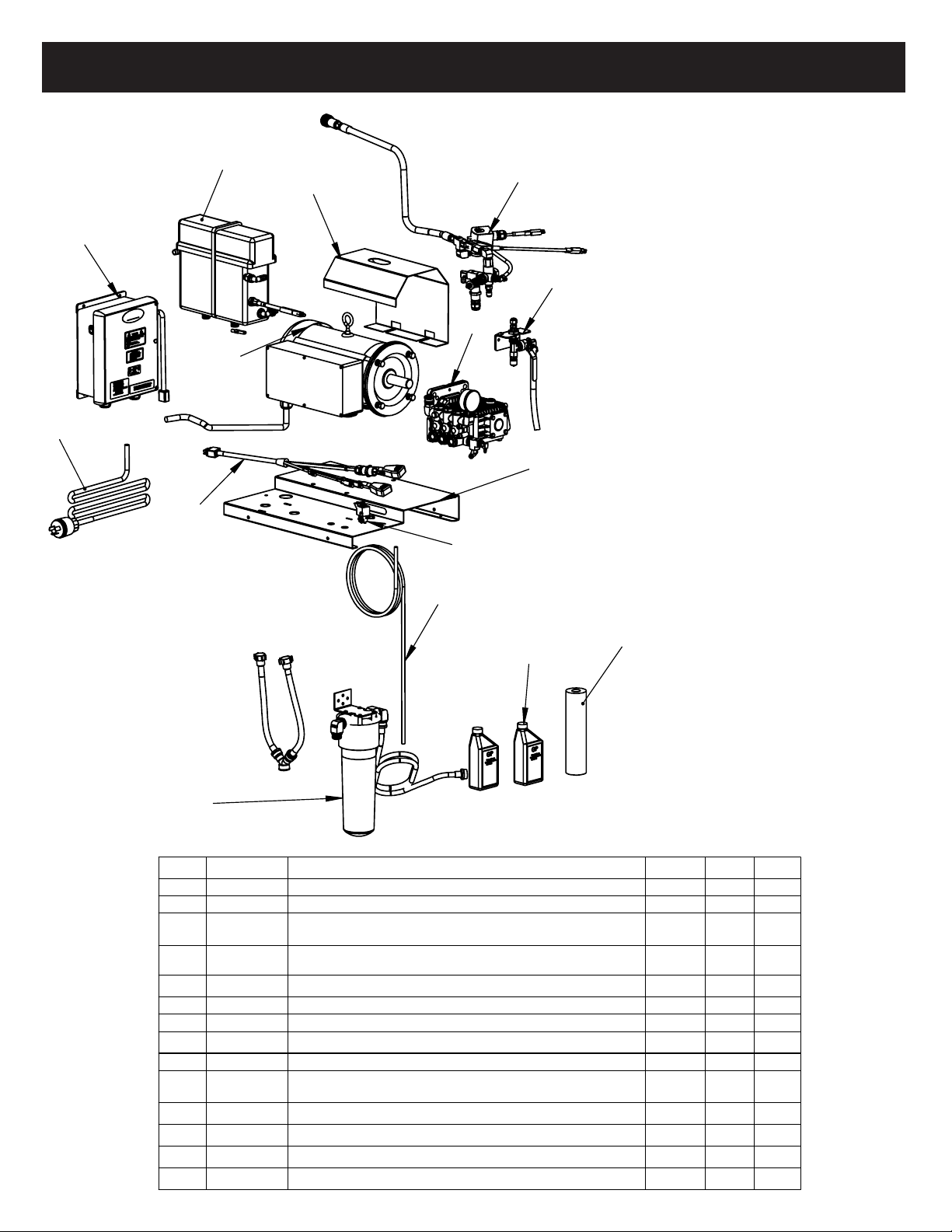
2000REY Parts Breakdown / List
Figure 7.
2000REY Exploded View
6
8
9
1
2
5
7
3
10
1
4
14
12
13
11
Item 9. 300-0840 is the
item changing for ETL
ITEM
PART No.
DESCRIPTION
QTY.
Length
U/M
1
300-1732
Unloader, 2000REY/WCY w/Flow Switch
1
2
300-1831
Frame Plate, 2000REY, SS
1
3
300-2584
Pump, 2000REY/WCY, 3.6G, Oil, Ga & Ftngs Price/Roll
1
4
300-2665
Cover, 5HP Motor, 16Ga, SS, 2000PE/REY
1
5
300-0442
Solenoid, Chemical Assy w/Fi�ngs
1
6
300-1671
Tank, 2000REY w/Float Switch
1
7
300-2840
Harness, Pump Assy, Branched 6 Pin
1
8
300-1883
Panel Master Control, 2000 Control Sys
1
9
300-0840
Pwr Cord, 6', 20V, 30A, Nema L630
1
10
300-1967
Valve, Bleeder 3/8 Tube, Central System
1
11
300-2700
Filter Assy, Water Supply, 2000 REY
1
12
300-3623
Replacement Filter, 5 Micron, 2.5x10
1
13
300-7605
Oil,16oz Btls, General Pmp, 100216
2
14
300-3120
Tubing, Vinyl, 1/4 ID x 3/8 OD, Clear
1 8
Ft
2000REY, Unit
SHEET 1 OF 1
01/03/18
SCALE: 1:50
WEIGHT:
REV
A
SIZE
Description:
DATE
Assembled Products Corp.
300-5074
DWG. NO.
6
8
9
1
2
5
7
3
10
1
4
14
12
13
11
Item 9. 300-0840 is the
item changing for ETL
ITEM
PART No.
DESCRIPTION
QTY.
Length
U/M
1
300-1732
Unloader, 2000REY/WCY w/Flow Switch
1
2
300-1831
Frame Plate, 2000REY, SS
1
3
300-2584
Pump, 2000REY/WCY, 3.6G, Oil, Ga & Ftngs Price/Roll
1
4
300-2665
Cover, 5HP Motor, 16Ga, SS, 2000PE/REY
1
5
300-0442
Solenoid, Chemical Assy w/Fi�ngs
1
6
300-1671
Tank, 2000REY w/Float Switch
1
7
300-2840
Harness, Pump Assy, Branched 6 Pin
1
8
300-1883
Panel Master Control, 2000 Control Sys
1
9
300-0840
Pwr Cord, 6', 20V, 30A, Nema L630
1
10
300-1967
Valve, Bleeder 3/8 Tube, Central System
1
11
300-2700
Filter Assy, Water Supply, 2000 REY
1
12
300-3623
Replacement Filter, 5 Micron, 2.5x10
1
13
300-7605
Oil,16oz Btls, General Pmp, 100216
2
14
300-3120
Tubing, Vinyl, 1/4 ID x 3/8 OD, Clear
1 8
Ft
2000REY, Unit
SHEET 1 OF 1
01/03/18
SCALE: 1:50
WEIGHT:
REV
A
SIZE
Description:
DATE
Assembled Products Corp.
300-5074
DWG. NO.
14
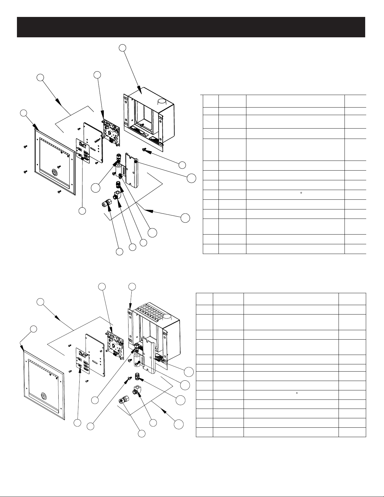
Recess Mount Remote Parts Breakdown / List
1
1
Figure 9.
Recess Remote
Exploded View
Figure 10.
Recess Remote
With Gripper
Exploded View

15
ENCLOSURE, REMOTE, LOW PROFILE
REDUCER, 3/8"MPT X 1/4"FPT,HEX BRASS
ADAPTER, STRAIGHT 3/8" TUBE X 1/4" MPT
BULKHEAD FITTING, 3/8" NPT
NIPPLE, HEX, 3/8", BRASS
COUPLER, Q.C., SHUTOFF, MALE PLUG, 3/8" FP
SCREW, #6-32 X 3/8"
PANEL, CONTROL, REMOTE STATION, SS, LOW PROFILE
ENCLOSURE, REMOTE, LOW PROFILE
REDUCER, 3/8"MPT X 1/4"FPT,HEX BRASS
ADAPTER, STRAIGHT 3/8" TUBE X 1/4" MPT
BULKHEAD FITTING, 3/8" NPT
NIPPLE, HEX, 3/8", BRASS
COUPLER, Q.C., SHUTOFF, MALE PLUG, 3/8" FP
SCREW, #6-32 X 3/8"
PANEL, CONTROL, REMOTE STATION, SS, LOW PROFILE
Surface Remote Parts Breakdown / List
ENCLOSURE, REMOTE, LOW PROFILE
REDUCER, 3/8"MPT X 1/4"FPT,HEX BRASS
ADAPTER, STRAIGHT 3/8" TUBE X 1/4" MPT
BULKHEAD FITTING, 3/8" NPT
NIPPLE, HEX, 3/8", BRASS
COUPLER, Q.C., SHUTOFF, MALE PLUG, 3/8" FP
SCREW, #6-32 X 3/8"
PANEL, CONTROL, REMOTE STATION, SS, LOW PROFILE
Figure 8.
Surface Remote
Exploded View
Spray Gun Parts Breakdown / List
Figure 11.
Spray Gun
Exploded View

16
HJJR Parts Breakdown / List
Figure 12.
HJJR
Exploded View
17
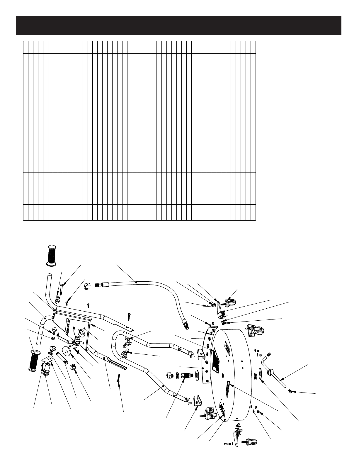
Hummer Jet Sr. Parts Breakdown / List
MODEL-HUMMER JET SR #2.5 NOZ
ITEM P ART# DES CR IPTIO N Q TY.
1 300-2939 GRIP, 7/8" X 5", WITH FLANGE BLACK
2
2 300-1644 BRACKET, M OUN T, QUICK CONNECT FOR HUMM ER JET S R
1
3 000-0041 CONNECT, QUIUCK S-O SOCKET 3/8" FPT, BRASS
1
4 300-1110 ELBOW, STREET, 3/8"M X F, 90° BRASS
4
5 300-1360 NIPPLE, 3/8"" X 4"" BRASS
1
6 300-1400
VALVE, BALL, 3/8"FPT X 3/8"FPT 3/16-24 THREAD MOUNT H O LES
1
7 3 0 0- 4 1 1 6 D E C A L, H U M M E R J ET, V A LVE P LATE 1
8 3 0 0 -3 8 5 1 P LA TE , V ALV E M O U N T F O R HU M M ER JET S R
1
9 300-4120 HAN DLE, U PPER ASSEM BLY HU M M ER JET SR., FO R M E D TU B E
2
10 300-0283
H O S E, H I- P RES , 3 /8 " X 2 8 " , B LU 3 /8 " M P T S W IV EL F ITTIN G (X 2 )
1
11 300-4117
SW IVEL, HI SPEED, HI PRESSU RE BU LKHEAD FITTING, 3/8" N P T
1
12 300-3909 T-HANDLE ONLY, HUMMER BOLT
1
13 300-4115
HAN DLE, LOW ER ASSEM BLY HUM M ER JET SR., FO RM ED TU BE
1
14 300-3896 DECAL, "WARNING: DO NOT USE ..
1
15 300-3899 BRACKET SET, HANDLE MOUNT, SET OF 2 (LEFT & R IG H T)
1
16 300-4130 DECK, HUMMER JET SR, ROUND STAINLESS,
1
17 300-3895 DECAL, "WARNING, KEEP HANDS.."
2
18 300-4118 WAND, ROTARY, T-BAR 18" HUMMER JET, 86-812
1
19 300-3893 NOZZLE, 1/8 M EG, #15O25, SS 15 DEG, #2.5 O RIFICE
2
20 300-4030 DECAL, LOGO, "SMT" RAISED PLASTIC, TRAPEZO ID 1
21 300-2818 BRACKET, CASTER, HUMMER JET SR 1/8" SS.,90 DEG.
4
22 300-2772
CASTER, SWIVEL, 3"DIA X1 1/4"W STEM 3/8-16 X 1". HUMMER
4
23 020-0058 WASHER,3/8X11/16X.094,LOCK,SS 4
24 021-0049 NUT,.375-18,HN,SS
4
25 300-1940 CAP BLK.313X.5 VINYL ROUND END
4
26 022-0005 BOLT,.25-20X.75,PHTS,SS 16
27 021-0038 NUT,.25-20.HN,NYLON LOCK,SS
12
28 020-0085 WASHER,1/4X9/16X.04,FLAT,SS
12
29 020-0053 WASHER,1 1/8X2 1/2X.1,FLAT,SS
2
30 300-3711 SKIRT, SPLASH,
1
31 300-3927 SPACER, COVED 5/16""
4
32 023-0137 SCREW,10-24X.375,BHCS,CZ
2
33 025-0014 BOLT,.25-2X 3,HH,CZ,5 1
34 023-0132 SCREW,#12X.75,HHFS,TEK,CZ
1
35 022-0023 SCREW,8-32X.5,PHTS,SS
9
36 020-0082 WASHER,.75X1X.125,RUBBER 1
37 300-1922 CAP, 2", VINYL, BLACK
1
38 020-0059 WASHER,#10X7/16X.061,FLAT,SS
9
39 021-0039 NUT,8-32,HN,NYLON LOCK,SS 9
40 023-0170 BOLT,.3125-18x2.25,SADDLE BOLT CZ
2
41 023-0105 SCREW,#8X.5,HHFS,TEK,CZ
4
42 029-0007 SCREW COVER,HINGED
2
43 000-0025 SPACER, ROUND TO FLAT,PLASTIC
4
44 300-3276 BOX, SHIPPING, HUM MER JETSR. 28"X24"X14"
1
45 021-0038 NUT,.25-20,HN,NYLON LOCK,SS
1
46 300-1911 COVER, PROTECTOR, NUT 1
Figure 13.
HJSR
Exploded View

18
IT EM P A R T # D E S C R IP T IO N Q TY.
1 300-2395 REEL, HEAVY DUTY, BLACK 1
2 000-1312 CLAM P, HOSE, 5/8", W /VINYL COAT 1
3 020-0061 W ASHER, FLAT, 2" O D X .88" ID,ZINC 1
4 300-1768 ASSY- SW IVEL, HOSE REEL 1
5 3 0 0-0 3 4 4 H A N D LE, H O SE R EEL, 4 " B LAC K P LASTIC 1
6 3 0 0 -1 6 47 D ECAL, "FO R SALES AND SERVICE" 1
7 022-0004 BO LT, HEX, 5/16-18 X1 4
8 300-1111 ELBOW , STREET, 1/2" M PT X 1/2" FPT 1
9 000-0039 CO UPLER, 1/2" X 3/8" FPT, BRASS 1
10 021-0034 NUT, 5/16-18 4
11 021-0018 NUT, .25-20, HN X .5 PHTS 3
12 022-0037 BOLT, .25-20 X .5 PHTS 3
13 300-0604 B R A K E, R E E L, A D JU S T A B LE F O R H EA V Y D U TY H O S E R EEL 1
NOT SHOWN 300-1845 DECAL, " SM T HD REEL" 1
14 300-0100 GRIP, HANDLE, HO SE REEL 1
15 300-2394 FRAME, HOSE REEL, HS, SQUARE 1
16 020-0085 W ASHER, 1/4 X9/16 X .04, FLAT, SS 1
17 021-0018 NUT, .25-20 HN NYLON LOCK 1
18 300-1911 CAP, PLASTIC PROTECTOR BLACK 1
19 000-1182 DECAL "PROTECT FROM FREEZING" 1
20 300-4063 DECAL " STO RE INDOO RS" 1
21 300-0091 BUM PER/FO OT RUBBER, HOSE REEL 2
22 300-0099 PLUG, SQUARE TUBING, PLASTIC 2
23 020-0028 W ASHER, 1/4 X 3/4 X .075 FLAT, CZ 2
24 023-0077 #10 X 1" TEK SCRW 2
25 300-1387 W HEEL, 10.5" DIAM ., 5/8" HUB 2
26 000-1123 C A P , R O U N D , LP E -B LK 1 1 /8 2
27 000-0014 CO LLAR, 5/8", #2 X 569 2
28
020-0050
W ASH E R , 3 /8 X 1 1 /2 X .1 , F LA T C Z 2
29 300-0175 HANGER, SPRAYGUN 1
30 022-0020 BOLT, .25-20 X 1.74=5 2
31 300-0147 HO SE, 12' , UM BILICAL 1
SMT-300HDR Parts Breakdown / List
Figure 14.
300 HDR
Exploded View

19

SMT-CSYSEXPRESS-SM-Rev 1-180719-EN Price and specifications are subject to change without notice . Printed in the USA.
115 E. Linden • Rogers, Arkansas 72756 USA
(479) 636-5776 • Fax: (479) 636-3245
www.SprayMasterTech.com
800-548-3373
Other manuals for 600REY
1
This manual suits for next models
2
Table of contents
Popular Cleaning Equipment manuals by other brands

HERKULES
HERKULES G550 owner's manual

Kärcher
Kärcher BRC 40/22 C instructions

IBS Scherer
IBS Scherer BK-50 Translation of the original instructions

THERMA-KLEEN
THERMA-KLEEN Ultra Propane 600 Operator's manual

Lincoln Electric
Lincoln Electric WELDLINE OPTICLEAN II Use and maintenance instructions

Getinge
Getinge Castle 7900 installation instructions


