JohnDow Industries JDI-6EV User manual

™
6 & 20-GALLON FLUID EVACUATOR
AND OIL DRAINS USER’S MANUAL
Part No. JDI-6EV and Part No. JDI-20EV
151 Snyder Ave.
Barberton, OH 44203
Rev 2/2021
READ AND SAVE THIS MANUAL
6
0242510513
3
FOR SERVICE ASSISTANCE, CALL 800-433-0708 OR VISIT JOHNDOW.COM

DANGER
WARNING
CAUTION
NOTICE
DANGER
WARNING
CAUTION
NOTICE
DANGER
WARNING
CAUTION
NOTICE
Indicates a hazardous situation that, if not avoided, could
result in death or serious injury.
Indicates a hazardous situation that, if not avoided, could
result in minor or moderate injury.
Indicates information considered important, but not
hazard-related.
2FOR SERVICE ASSISTANCE, CALL 800-433-0708 OR VISIT JOHNDOW.COM
GETTING STARTED
CAPACITY AND DIMENSIONS
U.S. ENVIRONMENTAL REGULATIONS
Product Specication JDI-6EV JDI-20EV
Tank Capacity 6.5 gallons (24.6 liters) 20 gallons (75.5 liters)
Overall Dimensions - H x W x D (in) 35” x 16” x 15” 38” x 19” x 21”
Overall Dimensions - H x W x D (cm) 89 x 41 x 38 97 x 48 x 53
Weight (Empty) 32 lb (14.5 kg) 50 lb (22.7 kg)
Air Supply Pressure (Evacuate Fluid into Drain) 100-120 PSI (6.9 - 8.2 MPa) Max.
Air Supply Pressure (Evacuate Drain) 10 PSI (0.7 MPa) Max.
• Hot motor oil removed from the engine may exceed 220°F and cause severe burns or injuries.
• Opening a hot system can cause these uids to be forcibly sprayed in all directions.
• Allow oil temperature to reach 194°F or less before extracting.
• Do not exceed 120 PSI (8.3 bar) supply pressure when generating the vacuum.
• Never exceed the MAX vacuum reading on the vacuum gauge.
• Wear proper personal safety equipment. Use extreme care when handling to prevent burns or injury.
• Do no leave the bowl unattended while creating the vacuum.
• Do not use if vacuum gauge is damaged. Replace immediately.
• Tank should be in good condition with no visible leaks. Repair leaks and clean up spills and properly dispose of
waste material.
• Monitor uid level in bowl and on drain. DO NOT overll.
• Closely monitor the ow out of the discharge hose to prevent spills when evacuating oil from the drain.
• Inspect all hoses and probes before use for cracks, kinks, damage, or blisters. Replace damaged hoses or
probes immediately.
• Close all valves when the oil drain is not being lled or emptied.
Before assembly, ensure you have all parts according to the components list below. If any parts are missing or
damaged, contact us for replacement.
General Information
Read equipment manual and this material before using this tank.
• Certain automotive uids are considered to be compatible for recycling used oil per the US Environmental
Agency (EPA). Other types of uids may not be mixed with used motor oil and must be handled separate-
ly. See denitions below:
Used Oil Includes:
• Snythetic Oil
• Engine Oil
• Transmission Oil
• Brake Fluid
• Hydraulic Oil
Cutting/Metal Oils
Used Oil Does Not Include:
• Antifreeze
• Gasoline
• Kerosene
• Petroleum Distillates and Solvents
• Vegetable or Animal Oils

3
FOR SERVICE ASSISTANCE, CALL 800-433-0708 OR VISIT JOHNDOW.COM
COMPONENTS
4
3
5
1
7
98
13
18
101112
14
15
6
2
17
16
A
1
2
6
4
3
18
17
16
5
7
9
10
11 12 13 14 15
22
23
DETAIL A
SCALE 1 : 2
20
21
Item
No. Description JDI-6EV
Replacement Parts
JDI-20EV
Replacement Parts
1 Oil Drain – –
2 Vacuum Gauge 6EV-1 6EV-1
3Venturi Vacuum Generator 6EV-2 6EV-2
4 Suction Hose 6EV-3 6EV-3
5Probe Tube 6EV-6 6EV-6
6 Drain Handle – –
7 Evacuation Hose 25HDC-1 25HDC-1
8 Caster – 20DCE-1
9Fixed Wheel 20DCE-7 20DCE-7
10 Flexible Probe (5mmx700mm) - Red PR5-700 PR5-700
11 Flexible Probe (6mmx700mm) - Green PR6-700 PR6-700
12 Flexible Probe (8mmx700mm) - Yellow PR8-700 PR8-700
13 Metal Probe (5mmx700mm) PRM5-700 PRM5-700
14 Metal Probe (6mmx700mm) PRM6-700 PRM6-700
15 Flexible Probe (7mmx1000mm) - Clear PR7-1000 PR7-1000
16 WYE Adapter 25HDC-Y-ADAP 25HDC-Y-ADAP
17 Safety Valve 20DCE-4 20DCE-4
18 Ball Valve AV-38 AV-38
19 Sight Glass S-KIT S-KIT
20 Probe Link O-Rings (4 Pack) EV-ORING –
21 Probe Link 6EV-DP –
22 1/2” Female Quick-Connect Fitting HA-15231-00 –
23 1/2” Male Quick-Connect Fitting HA-15232-00 –
JDI-6EV JDI-20EV
Items Not Shown
(2) Lock washers, (2) Large at washers, (2) Small at washers, (2) Cap nuts, (1) BMW adapter
ADP-BMW, (1) Mercedes-Benz adapter ADP-MCD, and (1) Volkswagen adapter ADP-VW.

4. FOR SERVICE ASSISTANCE, CALL 800-433-0708 OR VISIT JOHNDOW.COM
Generating the Vacuum:
Extracting Oil from Vehicle:
Emptying the Drain:
Maintenance & Storage:
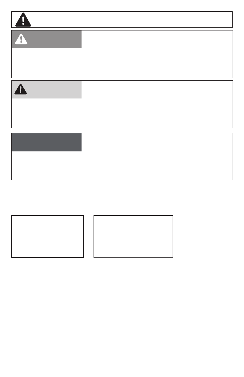
1. Close all ball valves as shown including:
A. Air shut off valve [A]
B. Below venturi [B] to tank
C. Probe coupler connection [C]
D. Air into tank (with safety valve) [D], used to empty tank
E. Discharge hose [E] at base of tank
2. Connect air supply to the venturi port (quick connect air tting
not included) [3]. Supply air pressure should be
between 100 and 120 PSI to achieve optimum vacuum.
3. To generate the vacuum inside the tank, open air supply [A]
and venturi valves [B]. Monitor the vacuum gauge and turn off
the air when the gauge is in the green zone by closing the ball
valves [A & B]. Disconnect the air supply. The tank is ready to
extract oil.
1. Select the appropriate size probe [10-15] and insert into the
engine oil dip stick tube or gear case port.
2. Remove protective cap from suction hose [4] and connect to
the probe connector.
3. To begin the extraction of oil from the vehicle / gear case,
open the probe coupler ball valve [C].
4. When complete, close valve [C] and remove probe.
1. Place hook end of Evacuation Hose [7] in the used oil
collection tank.
2. Close all ball valves except the ball valve below the evacua-
tion hose connector [E].
3. Connect shop air to the tank connector [D] (with safety valve).
Do not exceed 10 PSI supply pressure.
4. To evacuate the used oil from the drain, open the tank ball
valve [D].
5. When drain is empty, close tank ball valve [D] and disconnect
air supply.
1. Periodically check ttings for visible leaks. Service as necessary.
2. Keep cap on end of suction hose and keep all ball valves closed when not in use.
E
D
C
A
B
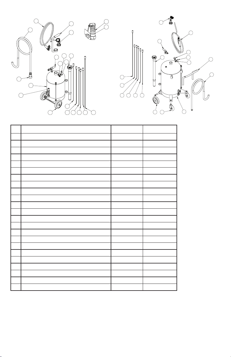
ASSEMBLY INSTRUCTIONS FOR JDI-6EV
ASSEMBLY INSTRUCTIONS FOR JDI-20EV
1. Place Probe Tube [5] in rings on side of Tank [1].
2. Place Flexible Probes [10, 11, 12, 15] and Metal Probes [13, 14] in Probe Tube [5].
3. Secure handle [6] to Tank using 4mm Hex Wrench.
4. Screw on Vacuum Gauge Kit Assembly [2] and hand tighten.
5. Connect 1” diameter Evacuation Hose [7], tighten with 1-1/16” Wrench.
JDI-6EV: 4mm Hex Wench JDI-20EV: 3/4” Wrench, 1/2” Wrench, Phillips Head Screwdriver
1. Assemble Front Casters [8], Washers, Lock Washers and Cap Nuts using 3/4” Wrench.
2. Assemble Rear Fixed Wheels [9], Washers and Screws using 1/2” Wrench.
3. Place Probe Tube [5] in rings on side of Tank [1].
4. Place Flexible Probes [10, 11, 12, 15] and Metal Probes [13, 14] in Probe Tube.
5. Secure Handle [6] to Tank using Phillips Head Screwdriver.
6. Screw on Vacuum Gauge Assembly [2] and hand tighten.
TOOLS & SUPPLIES NEEDED (not included)
This manual suits for next models
1
Table of contents
Popular Cleaning Equipment manuals by other brands

Edic
Edic PTAC Owner's/operator's manual

Meec tools
Meec tools 011387 operating instructions

ICE COBOTICS
ICE COBOTICS SoftBank Robotics Whiz quick start guide

Ultrawave
Ultrawave Q Series Operator's instruction manual

ARIETE
ARIETE TWIN AQUAPOWER 4241-4241 manual

Nilfisk-Advance
Nilfisk-Advance Liberty SC50 Instructions for use