SMW Autoblok KNCS-NB User manual

KNCS-NBX - E - 2011-11 - 1
POWER CHUCK
Type KNCS-NB
Type KNCS-NBX
INSTRUCTION MANUAL
QUICK JAW CHANGE


SMW-AUTOBLOK 3
!
!
Danger of injury or danger to life if instructions
are not followed.
Please note especially the sections which are
marked with the following signs:
Please read this service manual carefully befo-
re installation and use and always follow the
regulations.
Instruction manual
Quick Change Jaw
Power Chuck
Type KNCS-NB
Type KNCS-NBX
Thank you for purchasing an original SMW-AUTOBLOK
quick jaw change chuck.
This service manual contains the installation, the use and the
maintenance instructions of the quick jaw change chucks, type
KNCS-NB / KNCS-NBX.
SMW-AUTOBLOK reserves the right to make changes without
notice.
This service manual may not be - in whole or in part - copied
without our written agreement.
The service manual is a part of the power chuck KNCS-NB/
KNCS-NBX and must be passed to the new owner in case of
sale.
Contents
Declaration of incorporation 4
General safety instructions 5
Description of function 6
Technical data KNCS-NB 8
Technical data KNCS-NBX 12
Installation 14
Operation 16
Maintenance 19
Disassembling / Repair 20
Spare parts 22
Trouble shooting 24
Calculation formulas for practical use 26
Warranty 12 and 24 months 28
Documentation of Maintanance 30
Confirmation of receipt of the manual 35
Overview
Danger of damage to the machine, the power
chuck or the components.

4SMW-AUTOBLOK
Signature of responsible person
Declaration of incorporation
for a partly completed machinery
to machine directive 2006/42/EC
The manufacturer: SMW-Autoblok Spannsysteme GmbH
Wiesentalstraße 28
D-88074 Meckenbeuren
Tel.: +49 (0) 7542 - 405 0
herby declares, that the following product:
Product description: Power chuck
Application range: Installation in machine tool
Type: KNCS-NB / KNCS-NBX
is intended to be installed into a completed machinery. It must not be put into service until the
final machinery into which the partly completed machinery it is to be incorporated has been
declared in conformity with the provisions of the EU machine directive (2006/42/EC) Annex II,B.
Applied harmonized norms: DIN EN 1550
Date: 29.12.2009
Declaration of incorporation

SMW-AUTOBLOK 5
!6. Remaining risks
The type of components (shape, weight, unbalance, ma-
terial etc.) has a big influence on the system “machine
tool - power chuck - component”. For that reason there
is always a residual risk.
These residual risks must be calculated by the user and
have to be eliminated by suitable actions.
7. Jaws
Always use original SMW-AUTOBLOK base jaws and
monoblock jaws. Jaws of other manufacturers can cause
damage to the chuck or accidents.
Top jaws must be mounted with head socket screws of
the class 12.9 only. Tighten with the specified torque.
Always ensure sufficient length of thread engagement
(min. 1,25 x thread dia.)!
If the jaw height of special jaws exceeds the height of
the standard jaws, the max. actuating force of the chuck
must be reduced in order to avoid an excessive lever ac-
tion and thus damage to the power chuck.
At reduced actuating force, the max. speed must also be
reduced accordingly!
8. Maintenance
The power chuck must be maintained at regular intervals.
Check the conditions by measuring the gripping force
with static gripmeter.
Replace damaged parts with
original SMW-AUTOBLOK spare parts only.
Maintenance must only be carried out at safe spindle stop
of the machine.
9. Actuating cylinder
The actuation of the power chuck must only be carried
out by suitable cylinders in accordance with safety pre-
cautions.
When installing the power chuck on the machine with an
existing cylinder be sure that the actuating force of the
cylinder does not exceed the max. permitted actuating
force of the chuck.
If necessary reduce the actuating force of the cylinder.
Connecting and adapter parts must be specified for per-
manent load. Adjust and check the proximity switches for
the stroke control before starting the production.
For any problems or questions please contact
SMW-AUTOBLOK directly or one of our authorized
offices.
General safety instructions
1. Correct use
SMW-AUTOBLOK power chucks work safely and trou-
blefree if they are used according to their specification i.e.
to clamp components on turning machines.
Any other use can cause hazards.
2. Personnel
Power chucks must be installed, operated and maintained
only by qualified and regularly trained personnel.
3. Safety precautions to the lathe
Machine spindle may only start if the clamping pres-
sure in the cylinder is fully reached and the compo-
nent is clamped within the permissible working ran-
ge.
Chuck can only be opened when machine spindle is
stopped.
A signal must stop the machine spindle in case of
failure in the clamping pressure and workpiece must
remain clamped safely until machine spindle stops.
Repowering after power failure must not change the
original clamping mode.
During machining the power chuck and the clamped
component must be protected by safety guards.
Open machine door only when machine spindle is
completely stopped.
Maintenance and actuation of the power chuck must
only be carried out when machine spindle is stopped.
4. Technical details
The max. data, max. actuating force F, max. spindle speed
n are engraved on the chuck body. They must not be
exceeded. Also the summary of the total static gripping
force ȈFsp at max. actuating force is engraved on the
chuck body.
5. Max. speed
The max. spindle speed is only valid at max. actuating
force using the standard hard stepped top jaws type GST,
which are not exceeding the outer diameter of the chuck.
If, for special applications, special top jaws are used clam-
ping force and the max. speed must be calculated accor-
ding to VDI 3106 but not exceeding the max. permitted
speed. Heavy special top jaws have an especially big influ-
ence on the max. speed. During the machining operation
the centrifugal force increases or decreases the gripping
force.
OD clamping = decreasing
ID clamping = increasing
The calculated values should be measured with a dynamic
gripmeter type GFT-X.
General safety instructions
!
!
!
!
!
!
!
!
!

6SMW-AUTOBLOK
KNCS-NB 210-52-3-Z170
Size of center mounting
Size of short taper
Z = Center mounting
A = Short taper mounting
Number of jaws
SMW-AUTOBLOK Type
Chuck o.d.
Through hole /
bore
The codes on the description of the type have the following meaning:
Description of function
Pos. II
jaw disengaged
Pos. I
jaw engaged
Transportation thread
Mounting
Safety pin
safety lock
mechanism
Jaw disengaging
key
Jaw guideway
No. 1
Thread for fixtures
etc.
Chuck type
Base jaw
(pointed serration or
tongue and groove)
Jaw guideway
No. 2
Serial No.
Dummy
Mounting key
Bright jaws

SMW-AUTOBLOK 7
up to nowWedge bar
Safety pin
Safety pin
Jaw is inserted correctly.
The jaw is positioned in the guideway
min. as far to the center that the sa-
fety pin is actuated. This insures that
the complete serration of the wedge
bar / jaw is engaged and the key can
be removed.
Jaw is inserted incorrectly.
No jaw is in the guideway
Safety pin locks the wedge bar
Key cannot be rotated back / re-
moved.
KNCS-NB / KNCS-NBX jaw safety interlock (patented)
Description of function
Power transmission by means of the unique and a thousand
times proven wedge bar design.
The axial draw / push force of the actuating cylinder is trans-
mitted to the radial jaw grip force by means of tangential
movement of the wedge bars.
Suitable for very high speed without centrifugal force
compensation due to superb design.
Case hardened chuck body. All function surfaces are hard
machined. This guarantees highest rigidity, precision, re-
peatability and service life.
Patented quick jaw change system. For changing the
jaws the wedge bars are moved tangentially via a key and
cambolts.
Single disengagement / engagement of jaws.
Patented safety interlock of the jaws ensures that all serra-
tion of the wedge bar/master jaw are fully engaged and the
gripping force is transmitted safely.
If jaws are not inserted correctly the jaws cannot be enga-
ged and the key cannot be removed (see below). KNCS-NB / KNCS-NBX wedge bar design

8SMW-AUTOBLOK
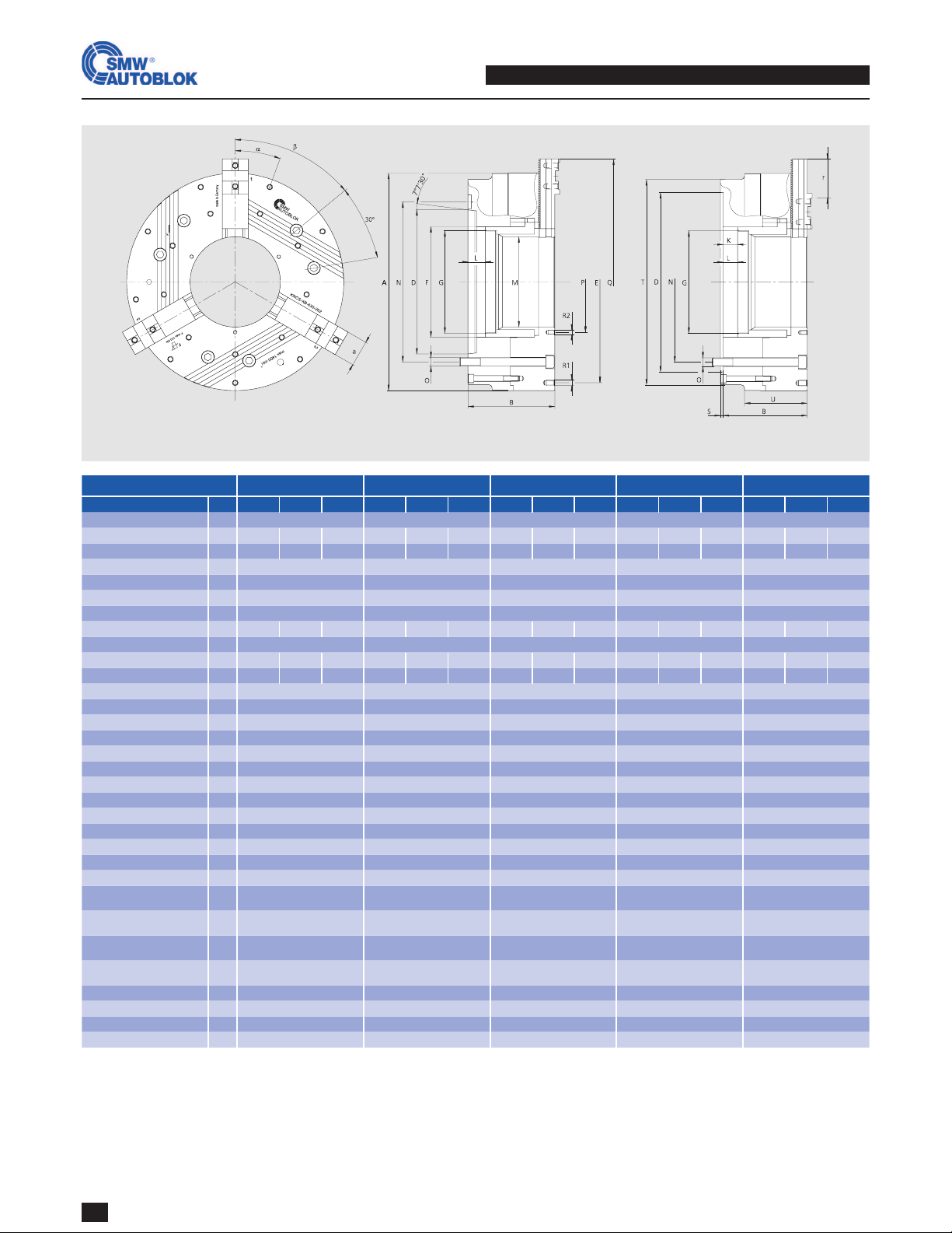
KNCS-NB 210-52 KNCS-NB 225-66 KNCS-NB 260-78 KNCS-NB 275-86 KNCS-NB 325-104
Z170 A6 A8 Z170 A6 A8 Z170 Z220 A6 A8 Z220 A6 A8 Z220 Z300 A8 A11
A215 225 260 275 324
B105 122 124 105 122 124 120 120 137 139 120 144 139 130 130 149 151
H6 D170 106.39 139.73 170 106.39 139.73 170 220 106.39 139.73 220 106.39 139.73 220 300 139.73 196.88
E168 180 210 210 268
F85 95 111 122 144
G1M60 x 1.5/16 M75 x 1.5/16 M90 x 2/20 M95 x 2/20 M115 x 2/22
G2M75 x 2/19 M85 x 2/19 M102 x 2/23 M110 x 2/23 M132 x 2/25
K22 22 25 25 25
max. L25 42 44 25 42 44 28 28 45 47 28 52 47 28 28 47 49
M52 66 78 86 104
N133.4 133.4 171.4 133.4 133.4 171.4 133.4 171.4 133.4 171.4 171.4 133.4 171.4 171.4 235 171.4 235
OM12 M12 M16 M12 M12 M16 M12 M16 M12 M16 M16 M12 M16 M16 M20 M16 M20
P72 82 95 105 130
Q261 271 318 322 376
R1M10/12 M10/12 M10/12 M10/18 M10/12
R2M6/10 M6/10 M8/14 M8/14 M10/12
S6 6 6 6 6
a28 28 35 35 50
-4.7 4.7 5.5 5.5 5.5
r28.3 33 33 38.5 49.5
6 7 6 7 9
Į° 60 60 60 60 60
ȕ°60 60 60 60 60
mm 6.0
22
6.0
22
7.0
25
7.0
25
7.0
25
kN 53 53 70 70 95
kN 100 100 135 135 180
5000 5000 4000 4000 3300
kg 24 26 26 26 29 29 40 40 43 43 48 53 50.7 65 65 68 68
kg·m
2
0.11 0.21 0.38 0.41 0.85
SIN-S 125/150 SIN-S 125/150 SIN-S 150/175 SIN-S 150/175 SIN-S 150/175/200
VNK 130-52 VNK 150-67 VNK 170-77 VNK 225-95 VNK 250-110
Technical data KNCS-NB
Subject to technical changes
Dimensions and position of base jaws are depending on top jaw type
SMW-AUTOBLOK Type
Mounting Size
Threaded ring / depth
Piston thread / depth
Piston stroke
Fixing bolt circle
Fixing bolt
Thread / thread depth
Thread / thread depth
Base jaw tooth pitch
Base jaw offset
Base jaw offset teeth
Stroke per jaw at
piston stroke Kmax.
max. actuating force
3-jaw chuck
max. total gripping force
3-jaw chuck
max. speed
3-jaw chuck rpm
Weight without jaws
Moment of inertia
rec. closed center cylinder Type
rec. open center cylinder Type
* Indirect mounting by reducing flange

SMW-AUTOBLOK 9
KNCS-NB 340-117 KNCS-NB 400-128 KNCS-NB 500-155 KNCS-NB 630-165 KNCS-NB 800-165
Z300 A8 A11 Z300 Z380 A11 A15 Z380 A11 A15 Z380 A11* A15 Z520 A15* A20
A340 400 500 630 800
B130 160 151 140 140 161 163 174 195 197 174 214 197 174 214 199
H6 D300 139.73 196.88 300 380 196.88 285.77 380 196.88 285.77 380 196.88 285.77 520 285.77 412.8
E270 330 420 420/585 420/585/750
F160 180 207 217 217
G1M125 x 2/22 M138 x 2/22 M165 x 2/25 M175 x 2/25 M175 x 2/25
G2M146 x 2/25 M160 x 2/25 M185 x 2/28 M195 x 2/28 M195 x /2/28
K25 32 42 42 42
max. L28 58 49 32 32 53 55 42 63 65 42 82 65 42 82 67
M117 128 155 165 165
N235 171.4 235 235 330.2 235 330.2 330.2 235 330.2 330.2 235* 330.2 463.6 330.2* 463.6
OM20 M16 M20 M20 M24 M20 M24 M24 M20 M24 M24 M20* M24 M24 M24* M24
P140 152 180 195 195
Q380 455 554 650 817
R1M10/16 M12/18 M16/25 M16/25 M16/25
R2M10/16 M12/18 M12/18 M12/18 M12/18
S6 8 8 8 8
a50 50 62 75 75
mm 5.5 5.5 7 7 7
r49.5 60.5 77 91 91
9 11 11 13 13
Į°60/35 60 60 20/9 x 40 20/9 x 40
ȕ°60 60 60 60 60
mm 7.0
25
8.0
32
10.0
42
10.0
42
10.0
42
kN 95 115 120 120 120
kN 180 240 250 250 250
3300 2750 1800 1500 1200
kg 77 88.5 82.5 111 111 116 116 225 231 231 390 411 398 620 660 635
kg·m
2
1.24 2.5 6.5 18 27
SIN-S 150/175/200 SIN-S 175/200 SIN-S 175/200 SIN-S 175/200 SIN-S 175/200
VNK 320-127 VNK 320-127 VSG 450-165 VSG 450-165 VSG 450-165
210-52
260-78
325-104
FG
F
800-165
630-165
500-155
400-128
FG
F
340-117
Technical data KNCS-NB
For highest speeds: flat gripping force curve
SMW-AUTOBLOK Type
Mounting Size
Threaded ring / depth
Piston thread / depth
Piston stroke
Fixing bolt circle
Fixing bolt
Thread / thread depth
Thread / thread depth
Base jaw tooth pitch
Base jaw offset
Base jaw offset teeth
Stroke per jaw at
piston stroke Kmax.
max. actuating force
3-jaw chuck
max. total gripping force
3-jaw chuck
max. speed
3-jaw chuck rpm
Weight without jaws
Moment of inertia
rec. closed center cylinder Type
rec. open center cylinder Type
The data in the diagrams refer to 3-jaw-chucks, newly maintained according to their
service manuals using SMW-AUTOBLOK K05 grease. The static and dynamic gripping
forces have been measured using standard soft top jaws, placed in a position not ex-
ceeding the outer diameter of the chuck.
FG Total grip force at 3 jaws [kN]
FG Total grip force at 3 jaws [kN]
Speed (rpm) Speed (rpm)
Safety advice / danger of damage:
When using taller / heavier jaws and / or clamping on a bigger dia-
meter reduce draw pull / rotating speed accordingly.
!

10 SMW-AUTOBLOK
L
B
N
G
S
Ha
a
b
L
B
N
G
S
Ha
a
b
KNCS-NB
210-52
KNCS-NB
225-65
KNCS-NB
260-72
KNCS-NB
275-86
KNCS-NB
315-91
KNCS-NB
340-117
KNCS-NB
400-128
KNCS-NB
500-155
KNCS-NB
630-165
KNCS-NB
800-165
- - Z170
064330 -Z220
064613 -Z300
064303
Z300
064306 - -
Z170
064334
Z170
069790
Z220
064331
Z220
069660
Z300
063852
Z300
069665
Z380
063950
Z380
064307
Z380
064548
Z520
064579
A 05 - - - - - - - - - -
A 06 064610 069791 064612 069661
A 08 064611 069792 064333 069662 064614 069666
A 11 - - - - 064302 069667 064304 064308 064577 -
A 15 - - - - - - 064305 064309 064549 064615
A 20 - - - - - - - - - 064616
KNCS-NB 210-52/225-65 260-72/275-86 315-91/340-117 400-128 500-155 630-165 800-165
138494 039624* 039626* 039629* 035565 035902 064604
B 28 35 50 50 62 75 75
H 32 40 45.8 45.8 57 57 57
L 85 104 115 125 160 200 287
N 20 20 20 26 30 30 30
S 10 12 12 12 18 18 18
M8 M12 M12 M12 M16 M16 M16
a 40 40 40 54 60 60 60
KNCS-NB 210-52/225-65 260-72/275-86 315-91/340-117 400-128 500-155 630-165 800-165
036292 035704 036167 036293 036294 036295 036296
B 28 35 50 50 62 75 75
H 32 40 45.8 45.8 61 61 61
L 85 104 115 125 160 200 287
N 1/16“x90° 1/16“x90° 1/16“x90° 3/32“x90° 3/32“x90° 3/32“x90° 3/32“x90°
17 21 21 25.5 25.5 25.5 25.5
G M12 M16 M16 M20 M20 M20 M20
a 2 x 23 30/28 30/28 2 x 38 3 x 38 4 x 38 6 x 38
b 11 14 14 17 17 17 17
KNCS-NB 210-52/225-65 260-72/275-86 315-91/340-117 400-128 500-155 630-165 800-165
- - 039628* 039631* 060561 060562 064590
B - - 50 50 62 75 75
H - - 45.8 45.8 57 57 57
L - - 120 146 168 203 287
N - - 19.02 19.02 19.02 19.02 19.02
S - - 12.7 12.7 12.7 12.7 12.7
- - 5/8-11 3/4-10 3/4-10 3/4-10 3/4-10
a - - 63.5 76.2 76.2 76.2 76.2
KNCS-NB 210-52/225-65 260-72/275-86 315-91/340-117 400-128 500-155 630-165 800-165
035566 035567 035568 035569 035570 035917 036708
B 28 35 50 50 62 75 75
H 32 40 45.8 45.8 61 61 61
L 85 104 115 125 160 200 287
N 1.5 x 60° 1.5 x 60° 1.5 x 60° 1.5 x 60° 3 x 60° 3 x 60° 3 x 60°
S 14 16 21 22 25 25 25
M12 M12 M16 M20 M20 M20 M20
a 2 x 25 2 x 30 2 x 30 2 x 45 1x50/1x60 2 x 60 4 x 60
b 11 11 14 17 17 17 17
KNCS-NB 260-72/275-86 315-91/340-117 400-128 500-155
UVB-B 250 UVB-B 315 UVB-B 400 UVB-B 500
238910 238911 238740 238912
B 35 50 50 62
H 110 115 125 160
h 81 81 91 113
L 109.5 170.5 148 175
5.9 11.9 17.6 32
Metric serration
3 x 60°
(Japanese standard)
Tongue and groove
American standard
Inch serration
3/32“ x 90°
Tongue and groove
KNCS-N
Chuck face
GBK-B
KNCS-N standard tongue & groove
Existing top jawBase jaw type
Supply range:
Chuck + disengaging key + mounting bolts + mounting key + set of coverplates without base jaws, without top jaws
Technical data KNCS-NB
Size
Spindle
mounting
Centering
rim small
Centering
rim large
GBK-BD
Inch serrated (for SMW-AUTOBLOK standard jaws)
Existing top jawBase jaw type
GBK-BA
American standard tongue & groove
Existing top jawBase jaw type
GBK-BM
Metric serration
Existing top jawBase jaw type
UVB-B
Soft wide monoblock jaws
Jaw type
Id. No.
Id. No.
G (metric)
S (ridge)
Id. No.
G (inch)
Id. No.
G (metric)
Jaw type
kg/set
Id. No.

SMW-AUTOBLOK 11
VNK
130/52
VNK
170/77
VNK
225/95
VNK
320/127
VSG
450/165
SIN-S
125
SIN-S
150
SIN-S
175
SIN-S
200
SIN-HL
100
SIN-HL
125
SIN-HL
150
SIN-HL
175
kN 58 76 100 123 138 71 108 150 196 49 77 108 154
6300 5000 4000 3200 2000 6000 6000 5000 4000 7000 6000 6000 5000
mm 52.5 77 95.5 127.5 165 - - - - - - - -
2 s
Actuating cylinder KNCS-NB / KNCS-NBX
Actuating cylinders with and without through hole
Examples for assembly
High-low clamping for thin-walled components
solid component
high gripping force
thin-walled component
low gripping force
roughing
finish
machining
chuck gripping force
without “high-low“ clamping with “high-low“ clamping
Principle
Function
Result
Open center with VNK Partial open center with SIN-S / SIN-HL
For easily deformed components SMW-AUTOBLOK offers
”high-low“ clamping. The gripping force of the chuck can be
reduced from a large amount of gripping force used in roug-
hing, to a smaller amount of gripping force for a finishing cut
without unclamping the component. The SMW-AUTOBLOK
closed center cylinder type SIN-HL and a modification of the
machine hydraulic are necessary.
In combination with a SMW-Autoblok ”high-low“ hydraulic
cylinder SIN-HL and suitable machine hydraulics, the KNCS-
NB / KNCS-NBX wedge bar system allows a monitored reduc-
tion of gripping force.
The component remains clamped in the chuck safely, howe-
ver, the stress of the component can be released. The ”high-
low“ cycle is programmable and is finished completely within
2 - 4 sec.
The result are round components with a minimum of defor-
mation.
For additional information please ask our engineers.
time
SIN-HL
Hydraulic closed center
cylinder for high-low clam-
ping with built-in safety
valves and piston stroke
control. Central through-
hole for air, oil or coolant
(pmax. = 70 bar)
SIN-S
Hydraulic closed center
cylinder with built-in safety
valves and piston stroke
control. Central through-
hole for air or coolant
(pmax. = 70 bar)
VNK
Hydraulic open center
cylinder with built-in safety
valves, piston stroke control
and coolant collector
(pmax. = 45 bar)
Type
Draw pull P
max
n
max.
r.p.m.
Through-hole
12 SMW-AUTOBLOK
KNCS-NBX 425-170 KNCS-NBX 530-210 KNCS-NBX 630-262 KNCS-NBX 800-262 KNCS-NBX 1000-262
Z380 A11 A15 Z380 A11 A15 Z520 A15 A20 Z520 A15 A20 Z520 A15 A20
A425 530 630 800 1000
B197 237 220 244 284 267 244 284* 269 244 284* 269 244 284* 269
H6 D380 196.88 285.77 380 196.88 285.77 520 285.77 412.77 520 285.77 412.77 520 285.77 412.77
E330.2 420 420/585 420/585/750 420/585/750/915
F222 262 320 320 320
GM202 x 2/25 M240 x 2/28 M297 x 2/33 M297 x 2/33 M297 x 2/33
K32 42 42 42 42
max. L32 72 55 42 82 55 42 82 67 42 82 67 42 82 67
M170 210 262 262 262
N330.2 235.0 330.2 330.2 235.0 30.2 463.6 330.2* 463.6 463.6 330.2* 463.6 463.6 330.2* 463.6
OM24 M20 M24 M24 M20 M24 M24 M24* M24 M24 M24* M24 M24 M24* M24
P194 235 292 292 292
Q487 598 745 915 1107
R1M12/16 M16/25 M16/25 M16/25 M16/25
R2M12/16 M16/25 M12/18 M12/18 M12/18
S8 8 8 8 8
T412 490 595 600 600
U137 167 182 182 182
a50 62 75 75 75
-5.5 7 7 7 7
r49.5 70 119 133 133
9 10 17 19 19
Į° 15°/12x30° 20°/9x40° 20°/9x40° 20°/9x40° 20°/9x40°
ȕ° 60 60 60 60 60
mm 8
32
10
42
10
42
10
42
10
42
kN 115 120 120 120 120
kN 240 250 250 250 250
2500 1500 1400 1000 850
kg 164 320 395 635 985
kg·m
2
4.3 13 23 54 125
SIN-S 175/200 SIN-S 175/200 SIN-S 175/200 SIN-S 175/200 SIN-S 175/200
VSG 450-165 VSG 550-205 VSG 550-205 VSG 550-205 VSG 550-205
Subject to technical changes
Dimensions and position of base jaws are depending on master jaw type
SMW-AUTOBLOK Type
Mounting
Size
Piston thread / depth
Piston stroke
Fixing bolt circle
Fixing bolt
Thread / thread depth
Thread / thread depth
Base jaw tooth pitch
Base jaw offset
Base jaw offset teeth
Stroke per jaw at
piston stroke K max.
max. actuating force
3-jaw chuck
max. total gripping force
3-jaw chuck
max. speed
3-jaw chuck rpm
Weight without jaws
Moment of inertia
rec. closed center cylinder Type
rec. open center cylinder Type
Technical data KNCS-NBX
* Indirect mounting by reducing flange

SMW-AUTOBLOK 13
L
B
N
G
S
Ha
a
b
L
B
N
G
S
Ha
a
b
KNCS-NBX
425-170
KNCS-NBX
530-210
KNCS-NBX
630-262
KNCS-NBX
800-262
KNCS-NBX
1000-262
Z380
160080
Z380
160090
Z520
069760
Z520
069770
Z520
069780
A 11 160081 160091 - - -
A 15 160082 160092 069768 069778 069788
A 20 - - 069769 069779 069789
KNCS-NBX 425-170 530-210 630-262 800-262 1000-262
035569 035570 035917 036708 -
B 50 62 75 75 -
H 45.8 61 61 61 -
L 125 160 200 287 -
N 1.5x60° 3x60° 3x60° 3x60° -
S 22 25 25 25 -
M20 M20 M20 M20 -
a 2 x 43 1 x 50/1 x 60 2 x 60 4 x 60 -
b 17 17 17 17 -
KNCS-NBX 425-170 530-210 630-262 800-262 1000-262
036631 060561 060562 064590 069807
B 50 62 75 75 75
H 45.8 57 57 57 57
L 146 168 203 286 384
N 19.02 19.02 19.02 19.02 19.02/3x
S 12.7 12.7 12.7 12.7 12.7
3/4-10 3/4-10 3/4-10 3/4-10 3/4-10/4x
a 76.2 76.2 76.2 76.2 76.2/3x
KNCS-NBX 425-170 530-210 630-262 800-262 1000-262
036293 036294 036295 036296 -
B 50 62 75 75 -
H 45.8 61 61 61 -
L 125 160 200 287 -
N 3/32“x90° 3/32“x90° 3/32“x90° 3/32“x90° -
25.5 25.5 25.5 25.5 -
G M20 M20 M20 M20 -
a 2 x 38 3 x 38 4 x 38 6 x 38 -
b 17 17 17 17 -
KNCS-NBX 425-170 530-210 630-262 800-262 1000-262
039629 035565 035902 064604 069806
B 50 62 75 75 75
H 45.8 57 57 57 57
L 125 160 200 286 384
N 26 30 30 30 30
S 12 18 18 18 18
M12 M16 M16 M16 M16
a 54 60 60 60 60
KNCS-NBX 425-170 530-210
UVB-B 400 UVB-B 500
238740 238912
B 50 62
H 125 160
h 91 113
L 148 175
17.6 32
Technical data KNCS-NBX
Metric serration
3 x 60°
(Japanese standard)
Tongue and groove
American standard
Inch serration
3/32“ x 90°
Tongue and groove
KNCS-N
GBK-B
KNCS-N standard tongue & groove
Existing top jawBase jaw type
Supply range:
Chuck + disengaging key + mounting bolts + mounting key + set of coverplates without base jaws, without top jaws
Size
Spindle
mounting
Centering
rim large
GBK-BD
Inch serrated (for SMW-AUTOBLOK standard jaws)
Existing top jawBase jaw type
GBK-BA
American standard tongue & groove
Existing top jawBase jaw type
GBK-BM
Metric serration
Existing top jawBase jaw type
Id. No.
Id. No.
G (metric)
S (ridge)
Id. No.
G (inch)
Id. No.
G (metric)
Chuck face
UVB-B
Soft wide monoblock jaws
Jaw type
Jaw type
kg/set
Id. No.
14 SMW-AUTOBLOK
!
!
!
!
3
4A
2
4A
2
1
3
1
4A
Insert draw tube with chuck into the machine spindle. Use
mounting belt or eye screw. KNCS-NB chucks carry a transpor-
tation thread from size 260 on.
Tighten draw bolt and push chuck onto the centering rim /
short taper.
Installation of chuck
Chuck without rotating ring nut
Partial open center
Wrong:
Draw tube not flush with
adaptor. Length of thread
engagement too deep
Correct:
Draw tube flush with
adaptor
Thread of draw tube / adaptor must be treated with copper pas-
te to avoid rust / seizing. Screw in draw tube into chuck
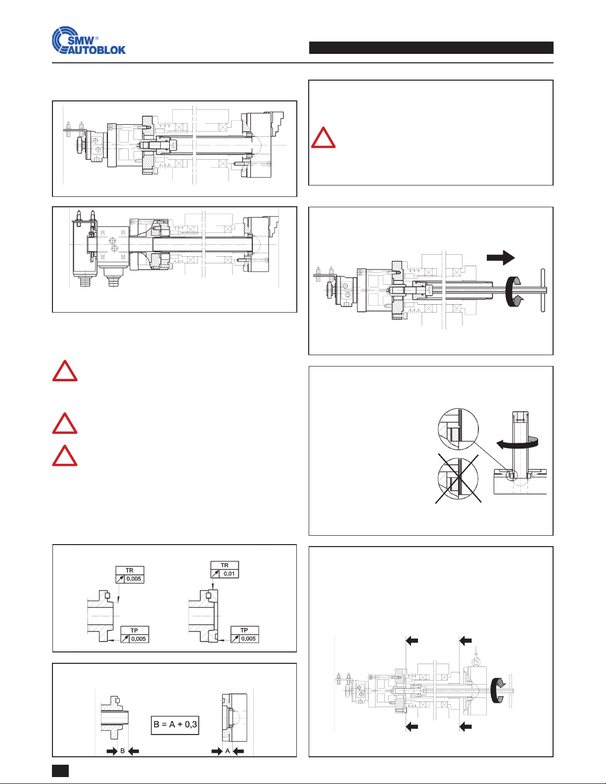
Check draw bar length with cylinder in frontend positi-
on. If necessary correct draw tube / adaptor!
Check spindle nose!
Open center
Partial open center
Installation of draw tube
Chuck without rotating ring nut
Partial open center
Also see page 17 Operating.
Move chuck piston into frontend position (chuck posi-
tion: OPEN). Release jaws by means of key and remove
one after another.
Check: All connecting and adaptor parts must be
calculated for continous operation!
Check: The max. draw pull of the actuating cylinder
must not exceed the max. actuating force of the
chuck! If necesary limit the pressure and secure the
limitation!
Before installing:
Installation
Examples for installation
Chuck with rotating ring nut:
Important: All rotating ring nut parts are highly-
loaded safety parts made of special steel!
When using special threaded rings use only origi-
nal SWM-AUTOBLOK blanks. Lock retaining ring
against loosening with screw in the proper way
(see page 21, pic. 5).
Always use SWM-AUTOBLOK special key (included
in delivery).
If there is no jaw in the guideway the key can
only be removed if the safety pin is actuated by
means of the dummy pin!
Cylinder in position “chuck OPEN”
Unscrew draw bolt and remove the draw tube from the spindle.
Removing draw tube
Chuck without rotating ring nut
Partial open center
Installation

SMW-AUTOBLOK 15
!
4B
!
4B
!
5
6
8
!
7
Danger of damage!
Never actuate the chuck when key is inserted!
Lubricate chuck at position ”chuck OPEN” . Always use SMW-
AUTOBLOK grease K05.
Lubrication see page 16.
Ordering no. 016440 K05 cartridge 500 g.
Ordering no. 011881 K05 can 1000 g.
Insert jaw 1, 2, 3 one after another into the guideways 1, 2, 3.
For jaw change please refer to page 17 / 18.
Check gripping force with gripmeter (GFT-X) at different actu-
ating pressures.
Lubrication
Insert mounting bolts ISO 4762 10.9 and thighten by hand. Ad-
just to lowest operating pressure and actuate cylinder: Position
“chuck CLOSED”.
Tigthen the mounting bolts with a torque wrench gradually one
after another. Do not exceed torque!
Mounting of chuck
Danger of damage to the chuck!
Do not tilt thread!
Do not apply force!
Never rotate spindle!
Rotate spindle by hand at adaptor or drive belt and screw in the
draw tube into the chuck to its end position. Push the chuck
onto the centering rim / short taper.
Cylinder in position “chuck OPEN”. Thread of draw tube/
adaptor must be treated with copper paste to avoid rust/seizing.
Position chuck concentric in front of the machine spindle by
means of suitable lifting equipment. Use mounting belt or eye
screw. KNCS-NB chucks carry a transportation thread from size
260 on.
Chuck without rotating ring nut
Open center
Observe correct length of thread engagement!
Draw tube face flush with adaptor
Installation of chuck
Installation of chuck
Chuck with rotating ring nut
Partial open center / Open center
Cylinder in position “chuck OPEN”. Thread of draw tube/
adaptor must be treated with copper paste to avoid rust/seizing.
Position chuck concentric in front of the machine spindle by
means of suitable lifting equipment. Use mounting belt or eye
screw. KNCS-NB chucks carry a transportation thread from size
260 on.
Insert the chuck key (standard equipment at option rotating nut)
through the chuck bore until the cams engage into the slots of
the rotating ring nut and screw the ring nut onto the draw tube
to its axial stop. Push the chuck onto the centering rim / short
taper.
Control
Check easy movement of the chuck. Chuck must open / close
easily at lowest clamping pressure.
Adjust the proximity switches on the actuating cylinder for stro-
ke control according to service manual of the cylinder.
Check jaw stroke.
Jaw stroke see technical details page 8 + 12.
Re-tighten the bolts with a torque wrench in position chuck
closed.
Danger of damage to the chuck!
Do not tilt thread!
Do not apply force!
Never rotate spindle!
Check radial and face runout
Bolt 10.9 ISO 4762 M10 M12 M16 M20 M24
Md (Nm) 48 70 170 300 500
Chuck type TR TP
KNCS-NB 210 0,02 0,03
KNCS-NB 260 - 400 0,03 0,03
KNCS-NB 500 - 630 0,05 0,05
Installation

16 SMW-AUTOBLOK
3
21
!
!
!
!
!
!
!
KNCS-NB/NBX 210 260 315 400 500 630 800 1000
GBK-B M8 M12 M12 M12 M16 M16 M16 M16
GBK-BD M12 M16 M16 M20 M20 M20 M20 -
GBK-BM M12 M12 M16 M20 M20 M20 M20 -
GBK-BA - - 5/8-11 3/4-10 3/4-10 3/4-10 3/4-10 3/4-10
Md (Nm) 35 65 65 65 170 170 170 -
Mounting surfaces of the top jaws must be straight
and on the same level. Otherwise the master jaw
gets distorted and locks in the guideway.
Boring ring
Boring ring
i.d. clamping
o.d. clamping
Highest repeatability can be achieved if you follow the following points:
Boring of soft jaws
Never grip boring ring with master jaw.Boring ring must be gripped as close to the grip-
ping area as possible.
For repeating jobs store top jaws with master
jaws as one unit.
Always machine top jaws under gripping force.
Use rigid boring ring.
Jaws of other manufacturers:
Safety risks due to wrong material or heat treatment
Danger of damage of your KNCS-NB / KNCS-NBX chuck due to wrong dimensions / tolerances
No warranty from SMW-AUTOBLOK
Use mounting bolts 12.9 ISO 4762 only. Always check correct length of thread engagement! Use torque
wrench and tighten gradually one after another.
Do not exceed torque (Md) otherwise master jaw gets distorted.
Use original SMW-AUTOBLOK master jaws GBK only! They
are marked on their face with the logo.
Mounting of top jaws on master jaws GBK
Operation

SMW-AUTOBLOK 17
1 3
24
!
!
!
Do not actuate foot pedal
Danger of damage to the
chuck!
Clean guideway and
lubricate. Lubricate
new jaw set in the
guideway and in the
serration.
Insert key and rotate
against spring tension
to pos. II and hold in
position.
Remove / reposition
jaw 1.
Changing / repositioning of the jaws is possible only in chuck
position “OPEN”.
Changing or re-positioning of the jaws
Do not actuate foot pedal
Danger of damage to the
chuck!
Do not actuate foot pedal
Danger of damage to the
chuck!
Jaw change
Foot pedal
chuck: OPEN

18 SMW-AUTOBLOK
7
86
5
!
!
!
!
!
!
!
!
Jaw change
Do not actuate foot pedal
Danger of damage to the
chuck!
Do not actuate foot pedal
Danger of damage to the
chuck!
Jaw safety interlock:
Key can only be removed in pos. I.
Key can only be rotated back from pos. II into
pos. I if a jaw is inserted correctly into the
chuck and the safety pin is actuated via the
jaw.
For installation and maintenance the key can be
removed in pos. I if the safety pin is actuated via
the dummy pin.
Danger of damage to the chuck!
Never actuate foot pedal (chuck) when key is
engaged for jaw change.
Never apply force!
Danger of damage to the chuck and actuating
cylinder!
Rotate key against spring tension to pos. II and hold in position.
Insert new jaw at least as far as necessary for the jaw to actuate
the safety pin.
Rotate key back to pos. I and remove. Jaw change of jaw 1 is
finished.
If no jaw is inserted, as example for maintenance or disassemb-
ling the chuck from the machine spindle, the key can be rotated
back to pos. I and removed if the safety pin is actuated via the
dummy pin.
For changing /
re-positioning
jaw No. 2 and jaw No. 3
repeat steps 2-6
Maintenance / disassembling / installation
Pos. II
Safety pin
Safety interlock: Key can only be removed in pos. I!
Do not actuate foot pedal
Danger of damage to the
chuck!
Pos. I
Pos. I
Safety pin

SMW-AUTOBLOK 19
1
3
2
!
!
!
!
!
Maintenace / Lubrication
Do not actuate foot pedal
Danger of damage!
Regular maintenance is the basis for correct func-
tion, high service life, precision and clamping
force of the clamping chuck.
Check gripping force regularly with gripmeter
(GFT-X)!
Never use coolants which dissolve the grease!
Maintenance intervals
at normal conditions / using coolant
Measurement Lubricate with
K05 grease
Disassemble + clean
see page 20 + 21
after operating
hours 20 1000
Lubrication of the chuck
Maintenance intervals
at rough conditions / using coolant
Measurement Lubricate with
K05 grease
Disassemble + clean
see page 20 + 21
after operating
hours 8 600
For optimal distribution of the grease do multiple jaw strokes
opening and closing.
At jaw change always clean and grease the guideway and the
serration.
Lubrication via 3 ball type grease nipples DIN 71412.
Can 1000 g
Id.No. 011881
Cartridge 500 g
Id.No. 016440
Grease gun for 14 Oz. cartridges to DIN 1284. (also refil-
lable from grease can 1000 g.)
Lubrication set
Id.No. 083726
Use original SMW-AUTOBLOK K05 grease!
The use of unsuitable lubricants can cause con-
siderable losses in clamping force or damage to
the clamping chuck.
Foot pedal
chuck:
CLOSED
First lubricate in chuck
positon “OPEN”...
1-2 strokes up
to size 275
2-3 strokes
from size 325
... then lubricate
in chuck position
“CLOSED”
1-2 strokes
up to size 275
2-3 strokes
from size 325
Foot pedal
chuck:
OPEN

20 SMW-AUTOBLOK
1
2
3
3A
3B
4
5A
5B
!
!Do not actuate foot pedal
Danger of damage to the
chuck!
Disassembling / Repair
Removal of the chuck from the machine spindle
Remove jaw 1 to 3. Key can be removed by actuating the safety
pin via dummy pin.
Use mounting belt to lift chuck. From size 260 mm on the
chucks carry a transportation thread for an eye bolt.
Close the chuck and remove the mounting bolts.
Open the chuck and release from centering rim dia./short taper
by means of light hit with a plastic hammer.
If the chuck does not release from the spindle:
Insert jaws again and do I.D. gripping on a solid ring or com-
ponent. The chuck is pushed off the spindle by means of the
actuation cylinder.
Partial open center
Unscrew draw bolt and remove chuck with draw tube from the
machine spindle.
Open center
Chuck without rotating ring nut:
Rotate spindle by hand at the flange or drive belt and screw out
the draw tube.
Open center
Chuck with rotating ring nut:
Insert key (standard equipment) through the chuck bore until
the cams engage into the slots and unscrew the threaded ring.
Never apply force!
Danger of damage to the chuck and actuating
cylinder!
This manual suits for next models
11
Table of contents
Other SMW Autoblok Industrial Equipment manuals

SMW Autoblok
SMW Autoblok Mario Pinto LT Operation instructions

SMW Autoblok
SMW Autoblok F180 User manual

SMW Autoblok
SMW Autoblok APS User manual

SMW Autoblok
SMW Autoblok VNK 70-37 Operation instructions

SMW Autoblok
SMW Autoblok M30 IOL User manual

SMW Autoblok
SMW Autoblok W-215 User manual

SMW Autoblok
SMW Autoblok SLX e-motion User manual

SMW Autoblok
SMW Autoblok ZHVD-SZ User manual


