6 SMW-AUTOBLOK
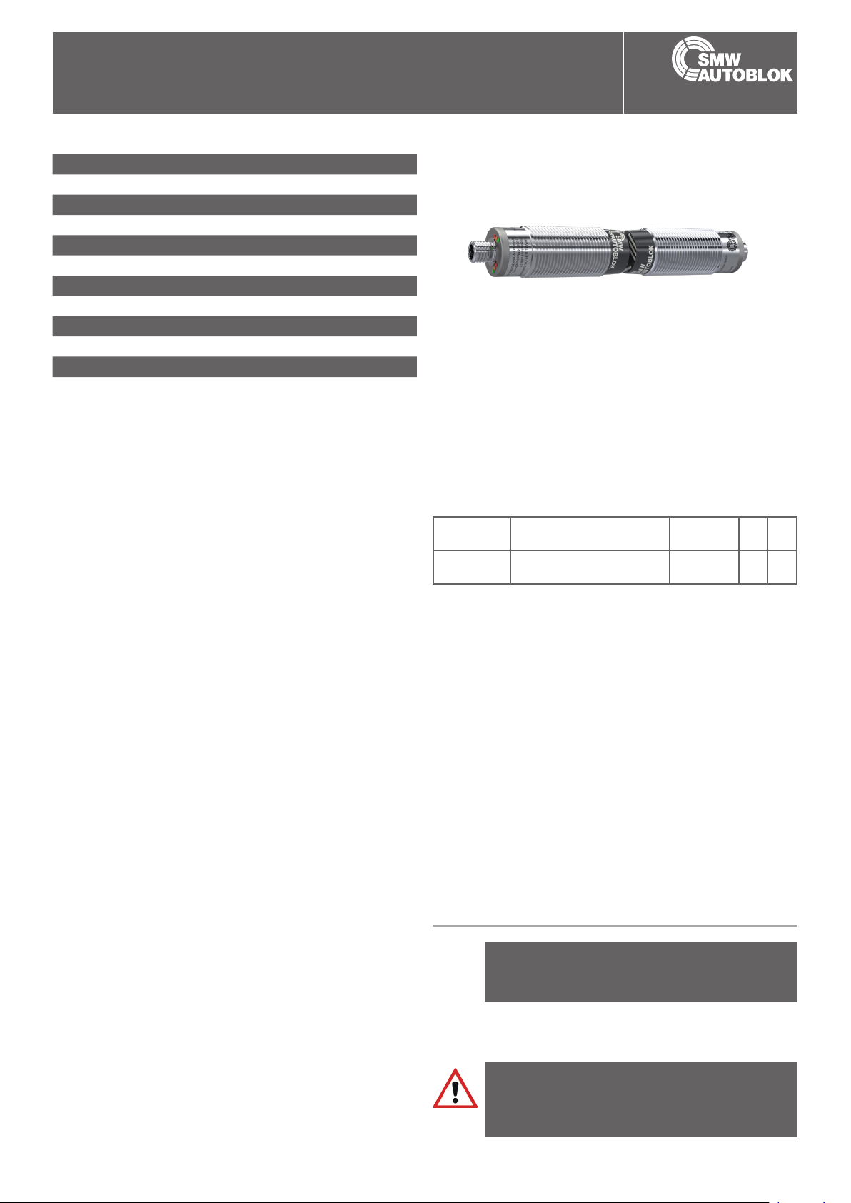
RemoteBase
M30-IOL
Axial coupler
Application/customer benets
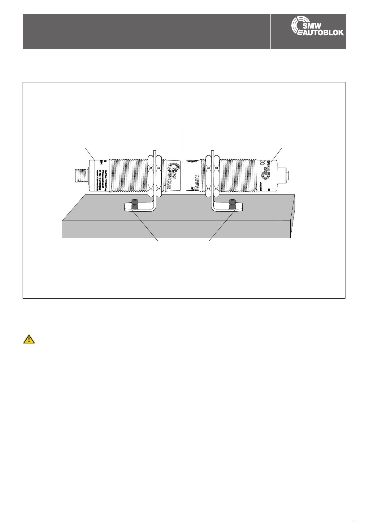
• Contact free, safe transmission of energy and signals
between moving / rotating and stationary components
• Application examples: Supply of sensors, Supply and monitoring of remote systems
• Dynamic Pairing
• Wear and maintenance free
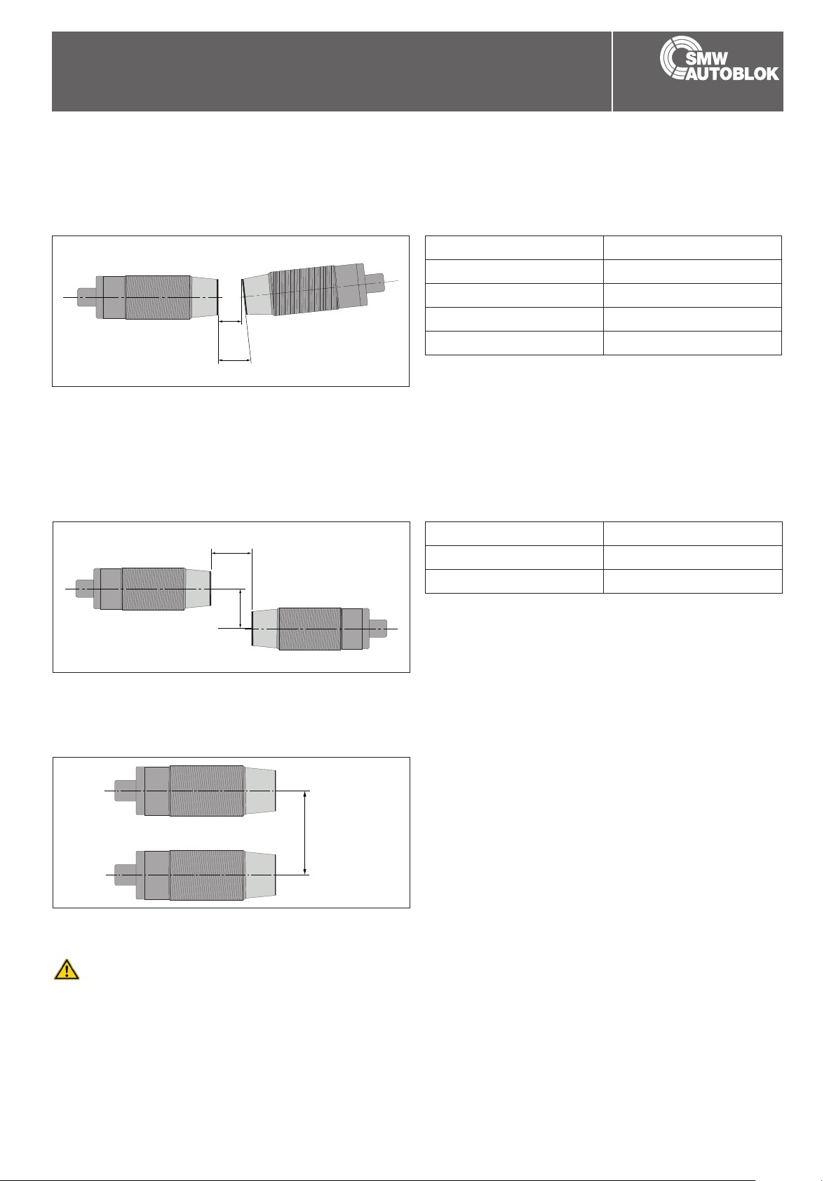
• Protective function: Temperature monitoring, foreign object detection, reverse polarity protection
• Multi-level LED with good visibility
Technical features
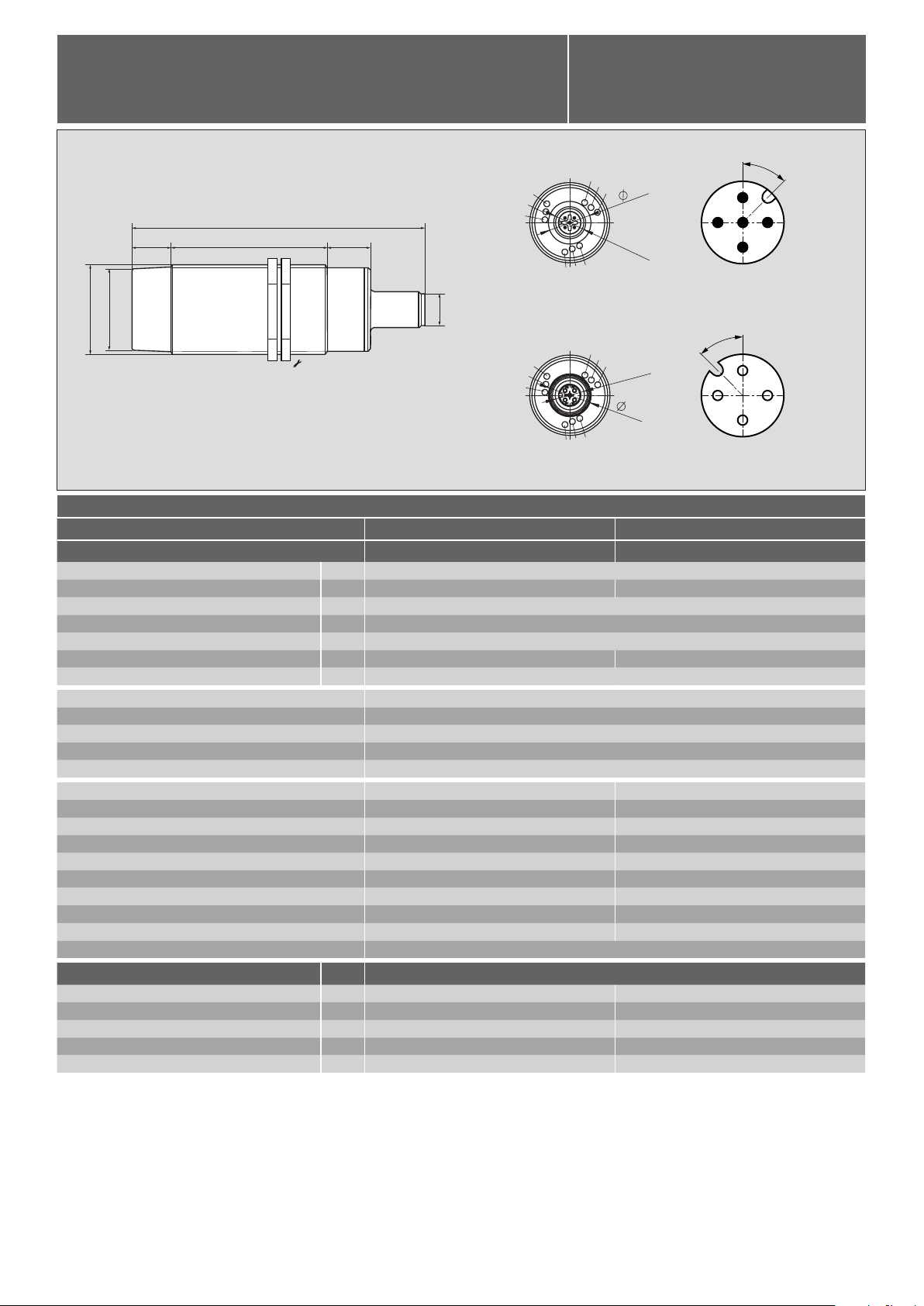
• Mounting M30 x 1.5
• Operating voltage 24 V (18 ... 30 V)
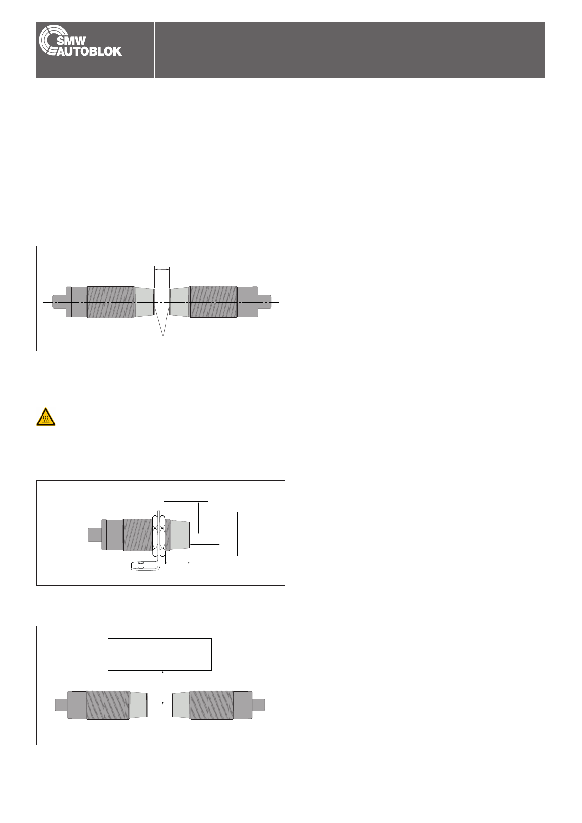
• Transmission distance 0 - 8 mm
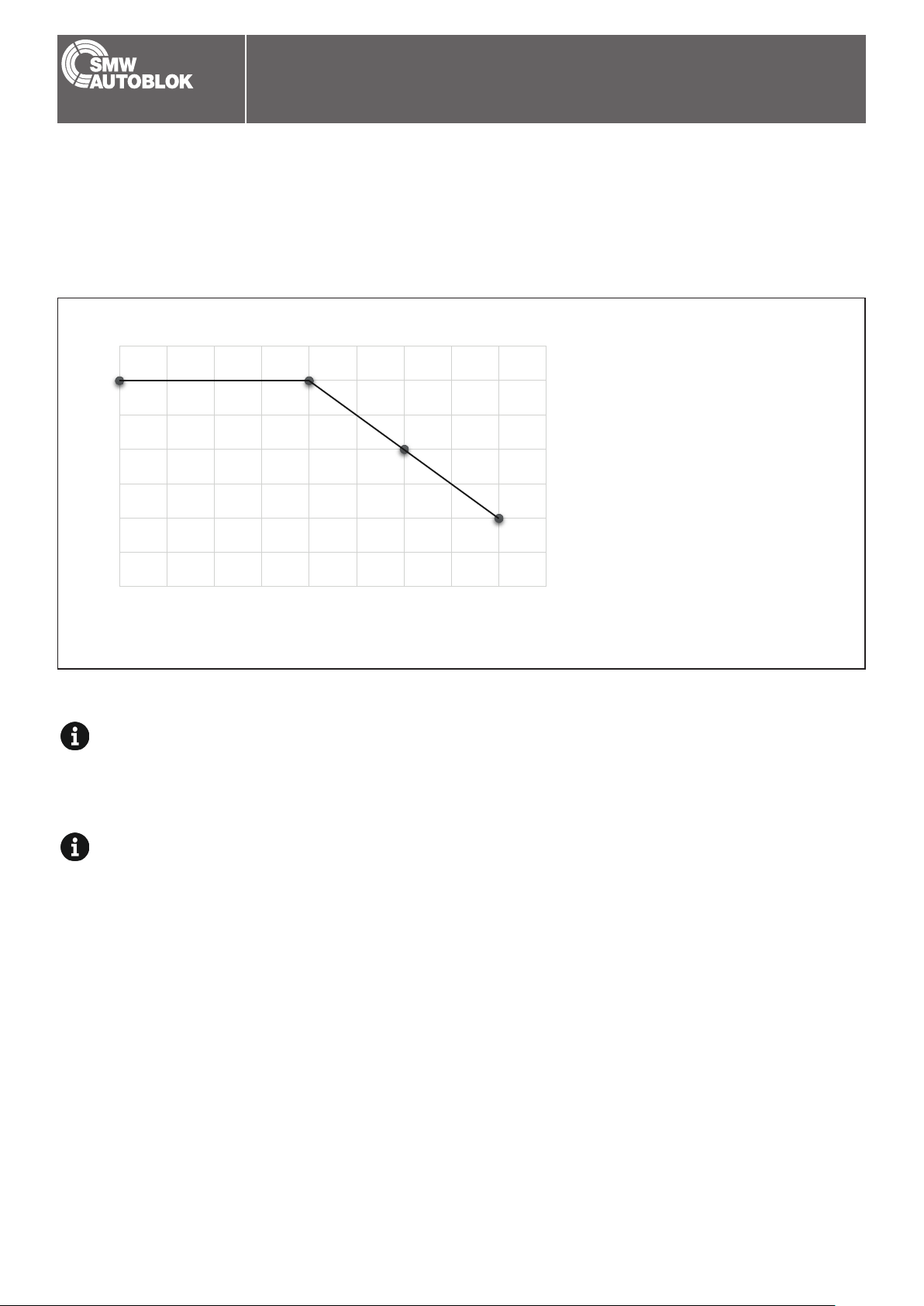
• Transmission of energy: 24 V / 12 W (500 mA) with a distance of 0 - 4 mm
• Transmission of signals: IO-Link (COM1, COM2, COM3), 1 digital signal
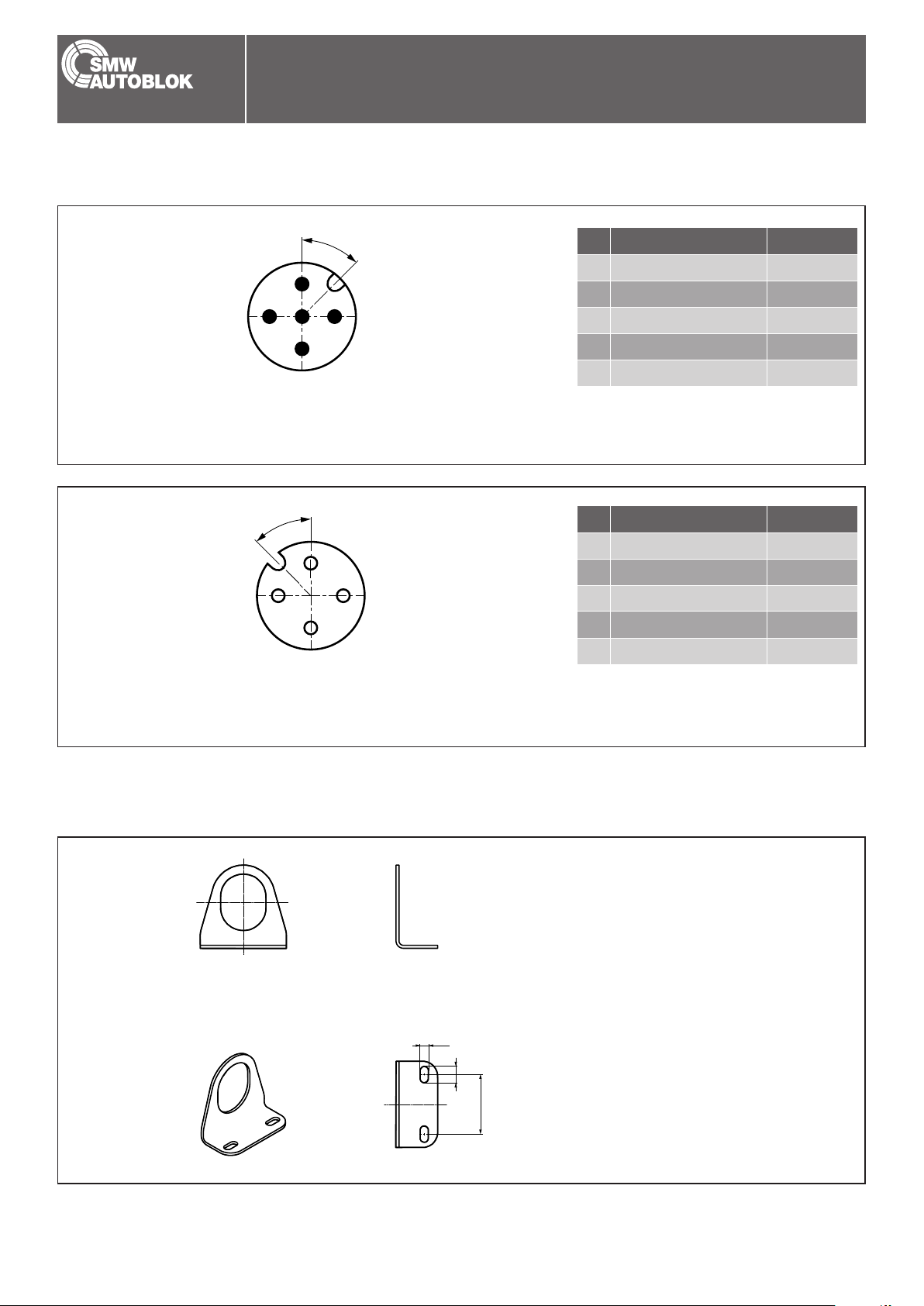
• Connection: Base male connector M12 (5-pin), remote female connector M12 (4-pin)
• Protection class IP 67
• Id. No. Base: 0E011604, Id. No. Remote: 0E011605
Subject to technical changes.
For more detailed information please ask our customer service.
Inductive Coupling Sytem
Block diagram:
IO-Link
Master
Energy
Signals
Function Base
LED Power
Color Green / red
Function
Off » Unit not supplied with voltage (or undervoltage)
On (green) » 24 V ok and mobile unit has been detected
Flashes 2 Hz green » 24 V ok but no mobile unit detected
Flashes 1 Hz red / green » Incompatible mobile unit detected
Flashes 2 Hz red » Foreign object detected
Flashes 5 Hz red » Internal error
LED IO-Link
Color Green / red
Function
Green » Signals IO-Link Operation
Green » On (SIO Mode Signal on)
Green » Off (SIO Mode Signal off)
Flashes 2 Hz red » Short circuit at the IO-Link PIN
Flashes 5 Hz red » Overload voltage output remote unit
LED Signal
Color Yellow
Function
Off » Digital input is not connected
or no mobile unit detected
On » Digital input is connected
Flashes 2 Hz » Digital input is connected
but short circuit at the output
Flashes 5 Hz » Overload voltage output mobile unit
Function Remote
LED Power
Color Green / red
Function
Off » Unit is not connected
On (green) » Unit coupled, voltage output DC 24 V ok
Flashes 2 Hz red » Connected but short-circuited at DC 24 V
Flashes 5 Hz red » Internal error
LED IO-Link
Color Green / red
Function
Green » Signals IO-Link operation according to IO-Link
specication (1000 ms on / 100 ms off)
Green » On (SIO Mode Signal on)
Green » Off (SIO Mode Signal off)
Flashes 2 Hz red » Short circuit at the IO-Link PIN
Flashes 5 Hz red » Overload voltage output mobile unit
LED Signal
Color Yellow
Function
Off » Digital input 2 is not connected
or no mobile unit detected
On / yellow » Digital input 2 is connected
■ Contact free transmission of energy and signals
0 - 8 mm
IO-Link-Device
IO-Link
COM1, COM2, COM3
24 V / 12 W (12 W with a distance of 0 - 4 mm)