•Beakta följande driftsinstruktionen
består av flera enskilda handlednin-
gar.
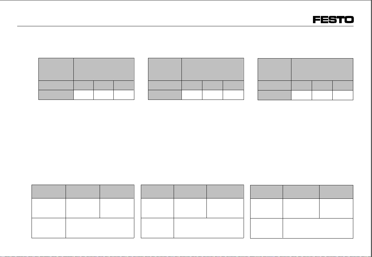
Luftbered-
ningsenhet Artikelnummer för
tillhörande enskilda
handledningar
Typ FRC-... LFR-... LOE-...
FRC-...-D-... 351 357 360 785 345 098
Montering
Om tryckluftstillförsel önskas från
höger:
•Vrid FRC-...-D-... 180° runt den
övre axeln.
För manometermontering: Se
driftsitruktionerna LF, LFM, LFR, LR.
Tekniska specifikationer
Typ FRC-...
-D-... FRC-...
-D-...-A
Tillåtet
primärtryck
p1
1,5 bar ...
max. 16 bar 1,5 bar ...
max. 14 bar
Arbetstryck-
intervall p20,5...12 bar
0,5...7 bar (för FRC-...-D-7-...)
•Please note that the operating in-
structions consist of several individ-
ual instructions.
Maintenance
unit
combination
Appropriate individual
instructions
Type FRC-... LFR-... LOE-...
FRC-...-D-... 351 357 360 785 345 098
Fitting
With supply of compressed air from
the right
•Turn the FRC-...-D-... 180° around
the high axis.
For fitting the manometer, see opera-
ting instructions LF, LFM, LFR, LR.
Technical specifications
Type FRC-...
-D-... FRC-...
-D-...-A
Permitted
primary
pressure p1
1.5 bar ...
max. 16 bar 1.5 bar ...
max. 14 bar
Working
pressure
range p2
0.5...12 bar
0.5...7 bar (at FRC-...-D-7-...)
•Beachten Sie, daß die Bedienungs-
anleitung aus mehreren Einzelanlei-
tungen besteht.
Wartungs-
geräte-
Kombination
Teile-Nummern
der zugehörigen
Einzelanleitungen
Typ FRC-... LFR-... LOE-...
FRC-...-D-... 351 357 360 785 345 098
Einbau
Bei gewünschter Zufuhr der Druckluft
von rechts:
•Drehen Sie die FRC-...-D-... um
180° um die Hochachse.
Zum Manometereinbau: siehe Bedie-
nungsanleitung LF, LFM, LFR, LR.
Technische Daten
Typ FRC-...
-D-... FRC-...
-D-...-A
Zulässiger
Vordruck p11,5 bar ...
max. 16 bar 1,5 bar ...
max. 14 bar
Arbeitsdruck-
bereich p20,5...12 bar
0,5...7 bar (bei FRC-...-D-7-...)
1
2
FRC-...-D-...
9610C D/GB/S 2


