SMW Autoblok F180 User manual
F180 Ethernet
Inductive coupler system
DEUTSCH
INSTRUCTION MANUAL
Date:
Version:
Language:
COPY OF THE
ORIGINAL
2022-10
P2
English
Preliminary


SMW-AUTOBLOK 3
5
6
8
10
17
18
Übersicht
INSTRUCTION MANUAL
Inductive coupler system
F180 Ethernet
Thank you for purchasing your F180 Ethernet inductive coupler
system.
.
This instruction manual contains the installation, the functional
description and the operation of the „F180 Ethernet“.
SMW-AUTOBLOK reserves the right to make changes without
notice.
This instruction manual is a part of the „F180 Ethernet “ and
must be passed to the new owner in case of sale.
This instruction manual may not be -in whole or in part- copied
without our written agreement.
Content
Overview
Safety instructions
Tecnical data
Description of function
Installation
Typeplate
Warranty
Maintenance
Troubleshooting
Accessories
Typeplate
Warranty
Conrmation of receipt of the manual
&Please read the instruction manual carefully
before installation and use and always follow the
regulations.
Please note especially the sections which are
marked with the following signs:
•Danger of injury or danger to life if instructions
are not followed.
•Danger of damage to the sensor, the machine or
the components.
0E011246-P2 Inductive coupler F180 Ether-
net Base
28.02.2022 V1 EN
0E011247-P2 Inductive coupler F180 Ether-
net Remote
28.02.2022 V1 EN
Validity:

4 SMW-AUTOBLOK
Einbauerklärung
SMW-AUTOBLOK 5
Allgemeine Sicherheitshinweise
!
Englisch
In case of doubts or questions please ask SMW-
AUTOBLOK or one of our authorized ofces.
7. Protection against electromagnetic elds during
operation and assembly
The permissible values according to VDE 0848 Part 3-1 are
observed from a distance of > 3 mm. Persons with physical
aids (e.g. pacemakers) may be exposed to health hazards
due to the magnetic elds emitted by the coupler system.
The minimum distance for this group of persons is > 5
mm. The operator must ensure that this minimum distance
is also maintained during operation by taking suitable
measures.
6. Caution: Hot surface!
Danger of burns from hot surfaces!
The active surface heats up even under normal operating
conditions.
Keep hands and objects away from the active surface.
Avoid contact of metallic objects on the active surface.
Fire hazard!
5. Operating faults
In case of defective and unrecoverable device malfunctions,
put the device out of operation and secure it against
unauthorized use.
4.
Duties of the operator
The operator must ensure that the locally applicable
national and international safety regulations are observed.
The unit may only be operated with an approved power
supply.
2. Authorized personnel
Installation and commissioning are only permitted by
trained specialist operators.
1. Intended use
The device is designed to transmit energy and signals
without contact. The system must not be used in
applications where the safety of persons depends on the
device function.
Liability claims against the manufacturer expire in the event
of damage caused by:
• unauthorized tampering
• use not in accordance with the intended purpose
• use, installation, handling contrary to the regulations of
these operating instructions.
3. Visual inspection
Please check the product for visible damage prior to use!
8. Certication
With the CE mark we conrm that our products comply
with the requirements of the EC Directives 2004/108/EC
(EMC) and the EMC Act.
In an accredited EMC laboratory, proof was provided that
the products meet the EMC requirements of the basic
technical standards:
• EN 61000-6-4 (emitted interference) and
• EN 61000-6-2 (immunity to interference)
General safety instructions
Danger!
Danger to the environment!
General precept sign!
Follow the instructions! Caution: Hot surface!
General warning sign!
!
!
Before the start up, the operating instructions must be
read carefully.
No access for persons with
pacemakers

6 SMW-AUTOBLOK
0 - 20 mm
24 V / 240 W
48 V / 400 W
-20° C ... +60° C -20° C ... +60° C
-20° C ... +60° C -20° C ... +60° C
0 mm ... 5 mm (24 V)
0 mm ... 3 mm (48 V)
0 mm ... 5 mm (24 V)
0 mm ... 3 mm (48 V)
24 V / 48 V -
-24 V DC / 10 A
48 V DC / 8,3 A
- 24 V DC / 4 A
15 A (24 V)
12 A (48 V) -
- < 50 mV
max. 100 mA -
< 1 s < 1 s
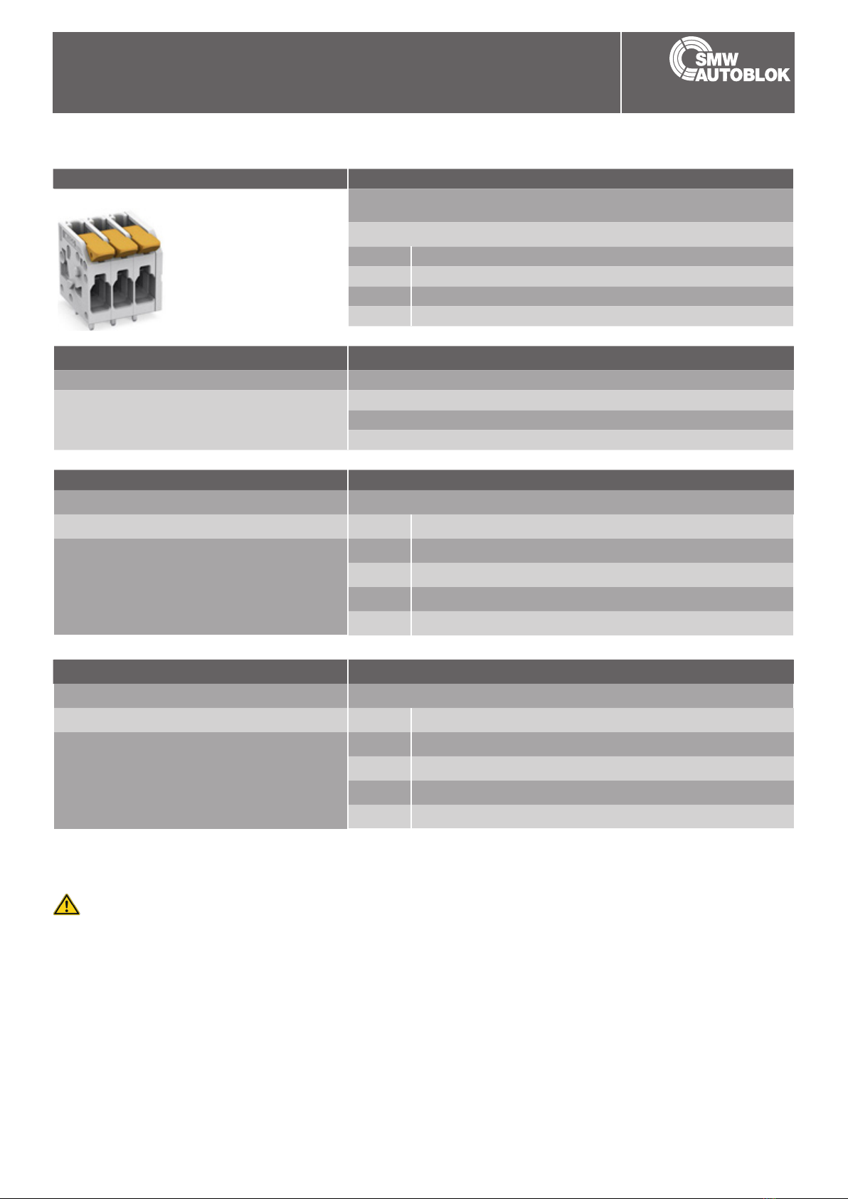
Base Remote
0E011246 0E011247
F180 Ethernet
Base Remote
Ethernet
Axial coupler
Application/customer benets
• Contact free, safe transmission of energy and signals
between moving / rotating and stationary components
• Application examples: Packaging machines, special machines,
Automation, Machine Tools, Printing Machines
• Substitution of slip ring / connector
• Dynamic Pairing
• Wear and maintenance free
• Protective functions: temperature monitoring, foreign object detection,
reverse polarity protection
• Multi-level LED with good visibility
Technical features
• Diameter 180 mm / Inner diameter 85 mm
• Supply voltage 24V / 48V
• Transmission distance 0 - 20 mm
• Transmission of energy 24V / 250W or 48V / 400W (selectable)
• Transmission of signals Ethernet 100 Base-T
• Transmission bandwidth Ethernet < 100 MBit
• Protection class: IP 67
Subject to technical changes.
For more detailed information please ask our customer service.
Block diagram:
Operating temperature (body surface)
Stocking temperature
Transmission distance
Operating voltage
Output voltage (Actuator supply)*
Output voltage (Sensor supply)*
Signal transmission Ethernet 100 Base-T Ethernet 100 Base-T
LED function display 3 LEDs 2x 3 LEDs 2x
Current consumption (base)
Overload protection / short-circuit protection
Reverse polarity protection
Data valid output
Ready for Operation
Inductive coupler F180 Ethernet
SMW-electronics Type
Id. No.
PLC
Energy
Signals
Inductive coupler system
■Contact free transmission of energy and signals
Signal transmission
Control
Power electronic
Signal transmission
Control
Rectier
Controller
24 V / 48 V
Controller
24 V
24 V / 10 A
Actuator
24 V / 2 A
Sensor
DAV /
Diagnosis
Ethernet
100BaseT
Galvanic
Isolation
Galvanic
Isolation
Galvanic
Isolation
DAV /
Diagnosis
Ethernet
100BaseT
Actuator
OFF
24 V /
48 V
48 V / 8,3 A
Actuator
SMW-AUTOBLOK 7
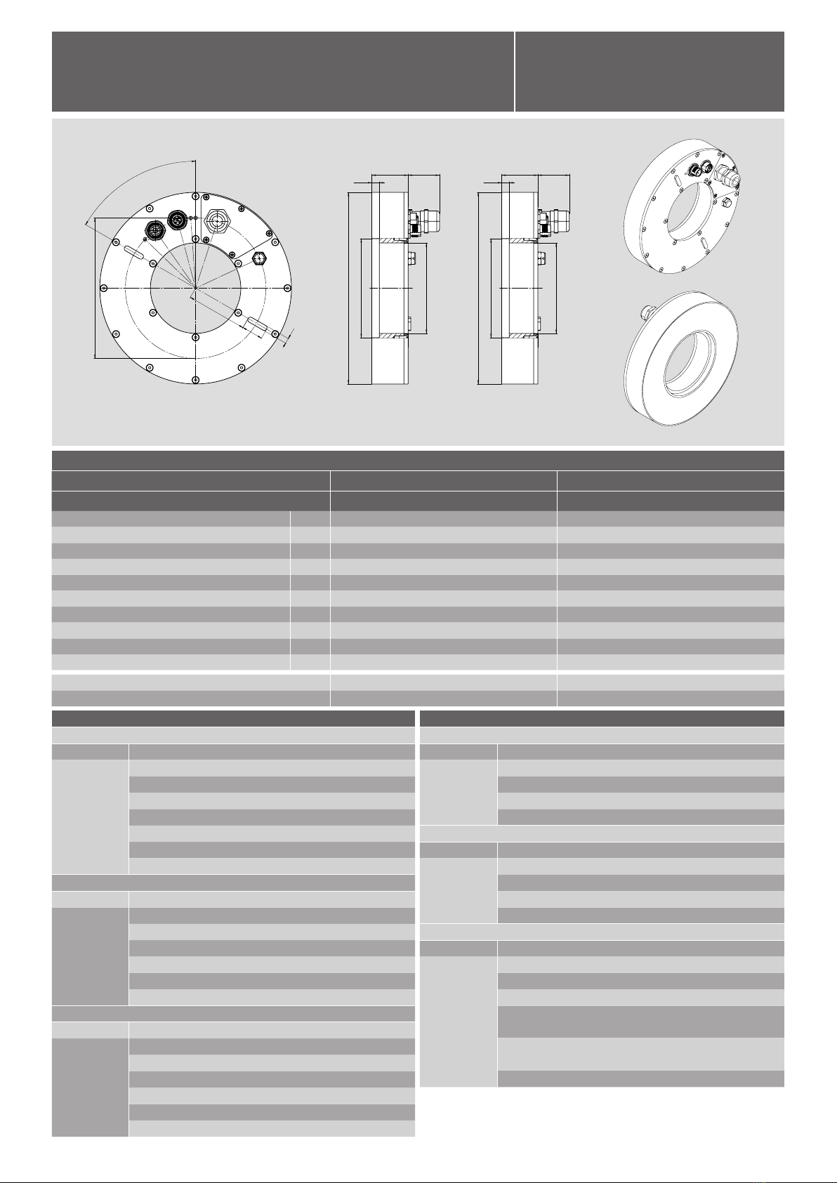
Base:Base / Remote: Remote:
60°
E
D
F
TK- Ø
132
H
H1
A
B
B1
C
60°
E
D
F
TK- Ø
132
H
H1
A
B
B1
C
Base Remote
0E011246 0E011247
Amm 180 180
Bmm 85 85
B1 mm 93 93
Cmm 29.5 29.5
Dmm 57 57
Emm 20 20
Fmm 5 5
Hmm 34 34
H1 mm 7 7
ɑ60 60
Al, GFK Al, GFK
IP 67 IP 67
F180 Ethernet
Axial coupler
Function Base
LED Power
Color Green / red
Function
Off » Unit not supplied with voltage (or undervoltage)
On (green) » Voltage ok and mobile unit has been detected
2 Hz green 50/ 50% » Operating temperature in critical range
1 Hz green 25/ 75% » Voltage ok but no mobile unit detected
1 Hz red/ green » Incompatible mobile unit detected
2 Hz red » Foreign element detected
5 Hz red » Internal error
LED Signal transmission Ethernet
Color Yellow / red
Function
Off » No mobile unit detected
On / yellow » Signal transmission ready
1 Hz yellow » Data packets are being transmitted
3 Hz yellow » 50% of the transmission bandwidth used (10 s)
8 Hz red » Data packets were discarded (in the last 10 s)
On / red » Error in data transmission (internal error)
LED Energy transmission
Color Yellow / red
Function
Off » No mobile unit detected
On (yellow) » Unit coupled, voltage output ok
1 Hz red/ yellow » Short circuit at voltage output sensor
3 Hz red/ yellow » Short circuit at voltage output actuator
3 Hz red » Short circuit at both voltage outputs
5 Hz red » Internal error
Function Remote
LED Actuator
Color Green / red
Function
Off » Unit not paired
On (green) » Unit paired, voltage output actuator ok
Flashes 2 Hz red » Unit paired but short circuit on actuator
Flashes 5 Hz red » Internal error
LED Sensor supply
Color Green / red
Function
Off » Unit not paired
On (green) » Unit paired, voltage output sensor (24 V) ok
Flashes 2 Hz red » Unit paired but short circuit on sensor (24 V)
Flashes 5 Hz red » Internal error
LED Signal transmission
Color Yellow / red
Function
Off » No mobile unit detected
On / yellow » Signal transmission ready
Flashes 1 Hz yellow » Data packets are being transmitted
Flashes 3 Hz yellow » 50% of the transmission bandwidth
used (10 s)
Flashes 8 Hz red » Data packets were discarded
(in the last 10 s)
On / red » Error in data transmission (internal error)
Subject to technical changes.
For more detailed information please ask our customer service.
Inductive coupler system F180 Ethernet
SMW-electronics Type
Id. No.
degree
Housing material
Protection class
Inductive coupler system
■ Stationary unit - Base
■ Mobile unit - Remote
8 SMW-AUTOBLOK
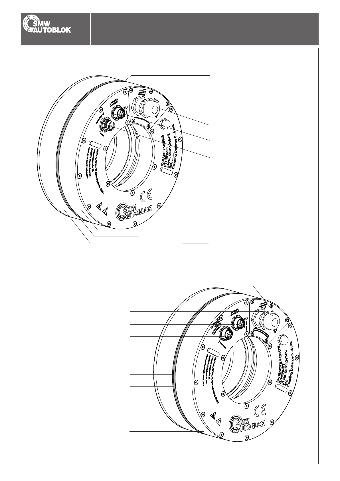
Description of function
Cable tting power cable M16
Transmission distance
Ethernet connection M12, female, D-coded
Diagnostic connection M12, plug, A-coded
Remote
Base
Coverage Energy
Coupler surface
View Base
View Remote
Cable tting power cable M16
Transmission distance
Ethernet connection M12, female, D-coded
Diagnostic connection M12, female, A-coded
Coverage Energy
Remote
Base
Coupler surface

SMW-AUTOBLOK 9
Description of function
The innovative F180 inductive coupling system is used to operate electronic components of automation technology such as eldbus gate-
ways, sensors or actuators on moving, dynamically variable machine and systems parts.
For this purpose, the coupling system transmits electrical energy and the necessary signals by using magnetic elds across an air gap.
This method is independent of movement and allows contact-free power and signal transmission into fast rotating system parts.
The inductive coupling system is designed for high power, so that it can operate a huge number of suitable actuators, such as, for example
magnet valves, servomotors or linear drives.
Description

10 SMW-AUTOBLOK
Installation
Terminal block inside the device
Screws for cover
Screws for cover
Socket screwed into housing
Lead through for electric line
Cap nut
Power connection
Cable tting M16
Cable tting M16 suitable for cable diameters from 5 bis 10 mm.
Note the specied tightening torque, 8 Nm for the cap nut.
The terminal block is accessible by removing the ve screws under the coverage energy.
1 - Vin
2 - GND
3 - FE

SMW-AUTOBLOK 11
Installation
Notice
Use base coupler 0E011246-P2 only with remote coupler 0E011247-P2.
The start-up can only occur after the entire transmission chain of base and remote has been comletely set up. The installation of the
components must always be performed in a (electrical) power-free state.
Operation can only be performed with a power supply limited to 15 A at a voltage up to 24 V/ 12 A at a voltage up to 48 V + or
another overcurrent protection device.
A correct coupling between Base and Remote is indicated by the Data Valid signal.
Start-up

12 SMW-AUTOBLOK
1 2 3
Installation
Connectors Base
Power supply
Terminal inside the unit (sealed) Terminal block with screw terminal (plug-in terminal) for 2.5mm² wires with
PG tting connection
PIN Function
1 DC 24/48 V +
2 DC 24/48 V -
3 FE (Functional ground)
Diagnose
Plug type M12 male 4-pin, A-coded
Pin assignment PIN Function
1 DC 24 V + (IN)
2 IN Actuator voltage ON/OFF
3 DC 24 V -
4 OUT Data Valid
Ethernet
Plug type M12 female, D-coded, inside the housing
Pin assignment PIN Function
1 TX +
2 RX +
3 TX -
4 RX -
SMW-AUTOBLOK 13
1 2 3
Installation
Actuator supply
Terminal inside the unit (sealed) Terminal block with screw terminal (plug-in terminal) for 2.5mm² wires with
PG tting connection
PIN Function
1 DC 24/48 V +
2 DC 24/48 V -
3 FE (Functional ground)
Output voltage selection
Switch inside the device Terminal block with screw terminal (plug-in terminal) for cable bridge (small) 2 pin
PIN Function
1 Sel 1 jumper set actuator U = 48 V
2 Sel 2 jumper not set actuator U = 24 V
Sensor supply diagnostic
Plug type M12 female 4-polig, A-coded
Pin assignment PIN Function
1 DC 24 V + sensor supply (OUT)
2 nc.
3 DC 24 V - sensor supply (OUT)
4 OUT Data Valid
Ethernet
Plug type M12 female, D-coded, inside the housing
Pin assignment PIN Function
1 TX +
2 RX +
3 TX -
4 RX -
Attention!
Damage to the remote unit due to overvoltage peaks if the cables are too long!
In order to meet the EMC requirements, the receiver cable must not be longer than 15 m. If a longer cable is nevertheless used,
take all steps to protect the receiver from overvoltage peaks.
Connectors Remote
14 SMW-AUTOBLOK
G
B
A
A
Installation
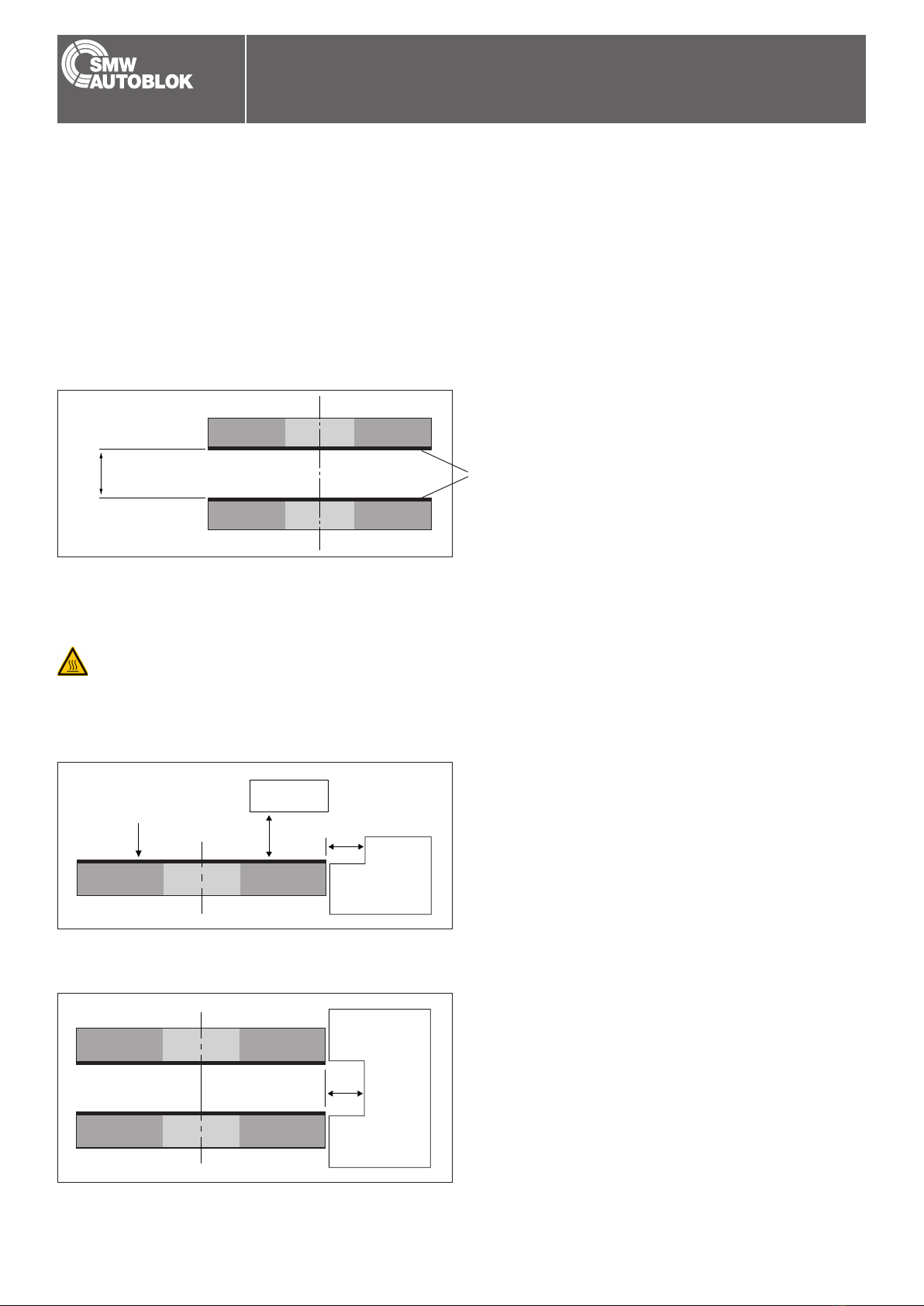
Operating voltage 24 V distance G ≤ 6 mm
Operating voltage 48 V distance G ≤ 3 mm
Distance A > 1 mm
Distance B > 30 mm
The base and remote units of the contactless transmission are integrated by mounting them in axial alignment in compliance with the
installation specications. The assembly must be performed in a (electrical) power-free state. The following sections describe valid instal-
lation instructions that must be strictly followed for correct operation.
We recommend to use the coupler with a coupling distance of 2 mm.
Distance to each other
Installation in metall
Metal objects in the area near the active coupling surfaces can heat up strongly due to the magnetic eld generated by the coupler.
Therefore, the specied minimum distances must be strictly followed when installing in metal.
Integration
Attention!
Active coupling surface
Not coupled state
Distance A > 1 mm
Coupled state
F180 Base
F180 Remote
Active coupling surface

SMW-AUTOBLOK 15
E
D
D
C
Installation
Permissible side offset
The maximum side offset between base and remote unit is ±1 mm.
Side offset E < 1 mm
Permissible angle offset
The permissible angle offset allows function in special mounting positions.
Attention!
The factors like enviroment temperature, distance, angle offset and side offset can affect the amount of energy transfer.
The coupler works optimal centric at D = 1 to 2 mm.
Distance D Angle °
0 mm
2 mm
< 2°
< 1°

16 SMW-AUTOBLOK
IO-Link Process Data Structure and Parameters
Notes
Englisch
SMW-AUTOBLOK 17
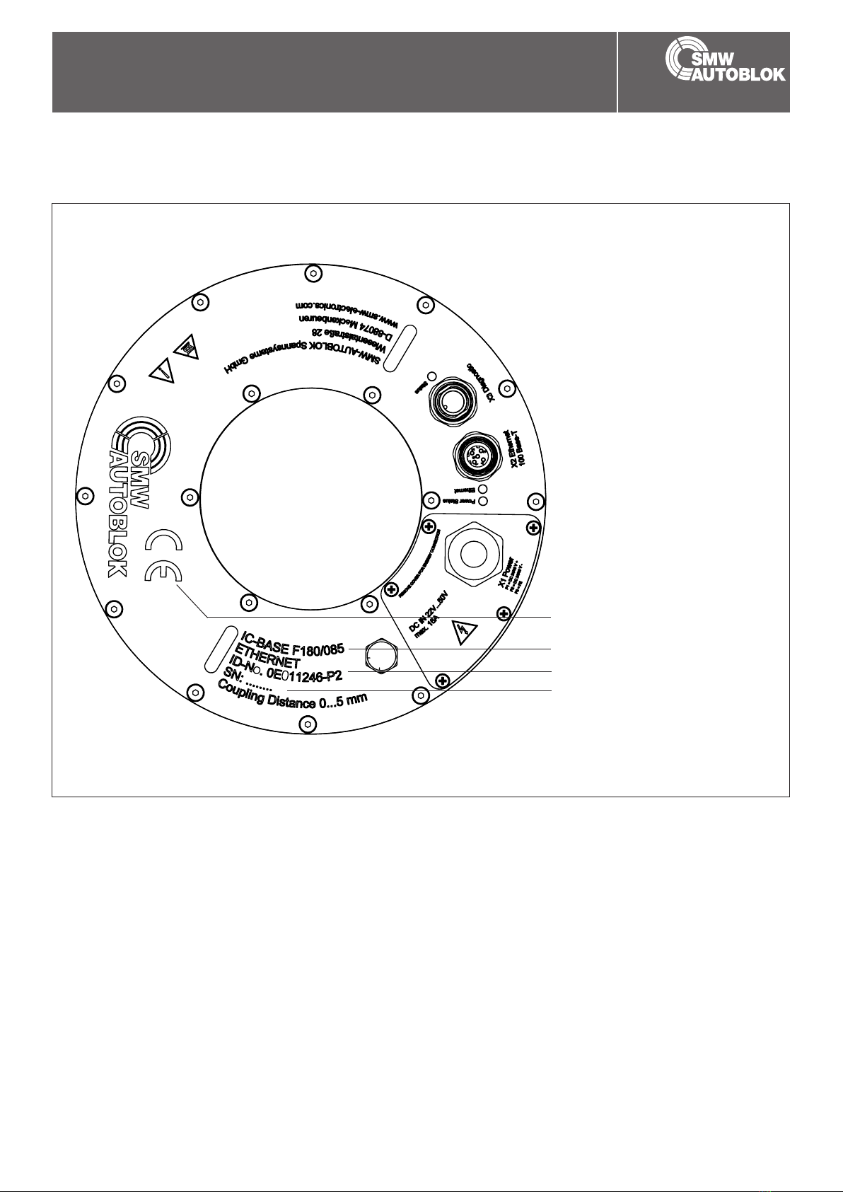
Typeplate
CE Label
Item Number
Type Information
Serial Number
Typeplate and contact
If you have any questions about the product or if you wish to place order, please specify the type and item number on the typeplate of
the inductive coupling system.
Contact:
SMW-AUTOBLOK Spannsysteme GmbH
Postfach 1151 • D-88070 Meckenbeuren
Wiesentalstraße 28 • D - 88074 Meckenbeuren
Tel.: +49 (0) 7542 - 405 - 0
Vertrieb Inland:
Fax: +49 (0) 7542 - 3886
Sales International:
Fax: +49 (0) 7542 - 405 - 181

18 SMW-AUTOBLOK
12 months warranty
Product:
SMW-AUTOBLOK guarantees the proper function of the inductive coupling system, if the operation and storage are in accordance
with the technical specifi cations of this operating manual.
In the case that the inductive coupling system does not meet the specifi ed requirements and values, after checking the facts, repair
or replacement will be carried out.
In case of production defects, the inductive coupling system will be repaired free of charge within the warranty period.
The warranty period will be 12 months starting from the date of purchase.
In order to maintain the warranty, the return must be carried out in the original packaging.
In addition, a description of the malfunction must be included.
The manufacturer otherwise retains the right not to admit warranty claims.
Warranty
Englisch
Inductive coupler system F180 Ethernet

SMW-AUTOBLOK 19

AUTOBLOK s.p.a.
Via Duca D‘Aosta n.24
Fraz.Novaretto
I-10040 Caprie - Torino
Tel. +39 011 - 9638411
Tel. +39 011 - 9632020
Fax +39 011 - 9632288
SMW-AUTOBLOK Spannsysteme GmbH
Postfach 1151 • D-88070 Meckenbeuren
Wiesentalstraße 28 • D-88074 Meckenbeuren
Tel. +49 (0) 7542 - 405 - 0
Vertrieb Inland: Fax +49 (0) 7542 - 3886
Sales International: Fax: +49 (0) 7542 - 405 - 181
SMW-AUTOBLOK Telbrook Ltd.
7 Wilford Industrial Estate
Ruddington Lane, Wilford
GB-Nottingham, NG11 7EP
Tel. +44 (0) 115 - 982 1133
SMW-AUTOBLOK
17, Avenue des Frères Montgoler - Z.I Mi-Plaine
F-69680 Chassieu
Tel. +33 (0) 4 - 727 - 918 18
Fax +33 (0) 4 - 727 - 918 19
SMW-AUTOBLOK Japan Inc.
1-56 Hira, Nishi-Ku
461-Nagoya
Tel. +81 (0) 52 - 504 - 0203
Fax +81 (0) 52 - 504 - 0205
SMW-AUTOBLOK Corporation
285 Egidi Drive - Wheeling, IL 60090
Tel. +1 847 - 215 - 0591
Fax +1 847 - 215 - 0594
SMW-AUTOBLOK IBERICA, S.L.
Ursalto 4 – Pab. 9-10 Pol. 27
20014 Donostia - San Sebastián (Gipuzkoa) (Spain)
Tel. +34 943 - 225 079
Fax +34 943 - 225 074
SMW-AUTOBLOK Poland Sp. z.o.o.
Ul Ligocka 103 - Building 8
40-568 Katowice
Tel. +48 (0) 664 673 428
SMW AUTOBLOK Makina San, Ve Tic. Ltd. ti.
Yeni ehir Mah, Osmanli Blv, Volume Kurtkoy Os
No: 9, Kat:1, D:4, 32912, Pendik Istanbul
Tel. +90 216 629 - 2019
SMW-AUTOBLOK Workholding Pvt. Ltd.,
Plot No. 4, Weikeld Industrial Estate,
Gat No. 1251, Sanaswadi, Tal – Shirur,
Dist – Pune. 412 208
Tel. +91 2137 - 616 974
Fax +91 2137 - 616 972
SMW-AUTOBLOK Mexico, S.A. de C.V.
Pirineos No. 515-B, Nave 16
Col. Industrial Benito Juarez
Micro Parque Industrial Santiago
Queretaro, Qro. C.P. 76130
Tel. +52 (442) 209 - 5118
Fax +52 (442) 209 - 5121
SMW-AUTOBLOK (Shanghai) Work Holding Co.,Ltd.
Building 6, No. 72, JinWen Road, KongGang
Industrial Zone, ZhuQiao Town, Pudong District
201323, Shanghai P.R. China
Tel. +86 21 - 5810 - 6396
Fax +86 21 - 5810 - 6395
AUTOBLOK Company Ltd.
NO.6, SHUYI RD., SOUTH DIST.,
TAICHUNG, TAIWAN
Tel. +886 4-226 10826
Fax +886 4-226 12109
SMW-AUTOBLOK s.r.o.
Merhautova 20
CZ - 613 00 BRNO
Tel. +420 513 034 157
Fax +420 513 034 158
SMW-AUTOBLOK KOREA CO., LTD.
1108 ho, Baeksang Startower 1st,
65, Digital-ro 9-gil, Geumcheon-gu
Seoul, ROK-08511, Korea
Tel. +82 2 6267 9505
Fax +82 2 6267 9507
SMW-AUTOBLOK Scandinavia AB
Kasernvägen 2
SE - 281 35 Hässleholm
Tel. +46 (0) 761 420 111
www.smw-autoblok.de
Spain
Mexico
Sweden / Norway
Korea
India
China
Japan
U.S.A.
Turkey
France
Great Britain
Taiwan
Czech Republic / Slovakia
Germany Italy
Poland
Table of contents
Other SMW Autoblok Industrial Equipment manuals

SMW Autoblok
SMW Autoblok W-215 User manual

SMW Autoblok
SMW Autoblok M30 IOL User manual

SMW Autoblok
SMW Autoblok VNK 70-37 Operation instructions

SMW Autoblok
SMW Autoblok Mario Pinto LT Operation instructions

SMW Autoblok
SMW Autoblok APS User manual

SMW Autoblok
SMW Autoblok ZHVD-SZ User manual

SMW Autoblok
SMW Autoblok KNCS-NB User manual

SMW Autoblok
SMW Autoblok SLX e-motion User manual


