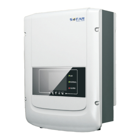
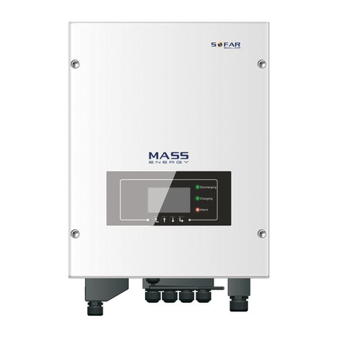
Sofar ME 5KTL-3PH User manual


TABLE OF CONTENT
I
Table of Content
Table of Content ..................................................................................................... I
1 About this manual .............................................................................................. 1
1.1 Copyright declaration ........................................... 1
1.2 Structure of the manual ......................................... 1
1.3 Scope ............................................................1
1.4 Target group .....................................................2
1.5 Symbols used .....................................................2
2 Basic safety information ....................................................................................4
2.1 Safety information .............................................. 4
2.2 Symbols and signs ............................................... 8
3 Product features ............................................................................................... 10
3.1 Product information ............................................ 10
3.2 Product dimensions ............................................. 11
3.3 Labelling on the device ........................................ 12
3.4 Functional features ............................................ 12
3.5 Connecting GTX 3000-H batteries (AMASS) ........................ 14
3.6 Connecting BTS 5K batteries .................................... 15
4 Installation .........................................................................................................19
4.1 Installation information ....................................... 19
4.2 Installation procedure ......................................... 19
4.3 Examination before installation ................................ 20
4.4 Connections .....................................................22
4.5 Tools ...........................................................23
4.6 Installation Environment Requirements .......................... 25

TABLE OF CONTENT
II
4.7 Installation location .......................................... 26
4.8 Unpacking the inverter ......................................... 27
4.9 Installation of the inverter ................................... 29
5 Electrical connections ..................................................................................... 31
5.1 Safety instructions ............................................ 31
5.2 Wiring overview ................................................ 32
5.3 System overview ................................................ 33
5.4 Electrical connection .......................................... 41
5.5 Connecting the PE cables ....................................... 42
5.6 Connecting the DC lines for the battery ........................ 43
5.7 Connecting the AC power cables ................................. 46
5.8 AC connector installation ...................................... 47
5.9 Communication interfaces ....................................... 50
5.10 Feed-in limitation function ................................... 66
5.11 System monitoring ............................................. 67
5.12 Installation of the WiFi, Ethernet stick ...................... 68
6 Commissioning the inverter ............................................................................ 73
6.1 Safety test before commissioning ............................... 73
6.2 Double Check ................................................... 73
6.3 Starting the inverter .......................................... 73
6.4 Initial setup .................................................. 74
6.5 Smartphone app SOFAR View ...................................... 80
6.6 Setting power quality response modes ........................... 81
7 Operation of the device ....................................................................................82
7.1 Control panel and display field ................................ 82
7.2 Standard display ............................................... 83

TABLE OF CONTENT
III
7.3 Energy storage modes ........................................... 84
7.4 Menu structure ................................................. 88
7.5 Firmware update ................................................ 96
8 Troubleshooting handling ............................................................................... 98
8.1 Troubleshooting ................................................ 98
8.2 Error list ......................................................99
8.3 Maintenance ................................................... 111
9 Technical Data ................................................................................................ 112


ABOUT THIS MANUAL
1
1 About this manual
This manual contains important safety information that must be
observed during installation and maintenance of the device.
Carefully read this manual before use and retain it for future
reference!
This manual must be treated as an integral component of the
device. The manual must be kept in close proximity to the device,
including when it is handed over to another user or moved to a
different location.
1.1 Copyright declaration
The copyright of this manual is owned by SOFARSOLAR. It may not
be copied – neither partially nor completely – by companies or
individuals (including software, etc.) and must not be
reproduced or distributed in any form, or with the appropriate
means.
SOFARSOLAR reserves the right to final interpretation. This
manual may be amended following feedback from users or customers.
Please consult our website at http://www.sofarsolar.com for the
latest version.
The current version was updated on 1/16/24.
1.2 Structure of the manual
This manual contains important safety and installation
instructions that must be observed during installation and
maintenance of the device.
1.3 Scope
This product manual describes the installation, electrical
connection, commissioning, maintenance and fault elimination
procedures of the
ME 5K...20KTL-3PH inverters.

ABOUT THIS MANUAL
2
1.4 Target group
This manual is intended for specialist electrical engineers who
are responsible for the installation and commissioning of the
inverter in the PV system, as well as the PV system operators.
1.5 Symbols used
This manual contains information on safe operation and uses
symbols to ensure the safety of persons and property as well as
the efficient operation of the inverter. Please read through the
following symbol explanations carefully in order to prevent
injury or property damage.

ABOUT THIS MANUAL
3
DANGER
Non-observance will result in death or serious injury.
Follow the warnings in order to prevent death or
serious injury!
WARNING
Non-observance may result in death or serious injury.
Follow the warnings in order to prevent serious injury!
CAUTION
Non-observance may result in minor injury.
Follow the warnings in order to prevent injury!
ATTENTION
Non-observance may result in property damage!
Follow the warnings in order to prevent damage to or
destruction of the product.
NOTE
Provides tips essential to the optimal operation of
the product.

BASIC SAFETY INFORMATION
4
2 Basic safety information
NOTE
If you have any questions or problems after reading
the following information, please contact SOFARSOLAR
This chapter details the safety information pertaining to the
installation and operation of the device.
2.1 Safety information
Read and understand the instructions of this manual, and be
familiar with relevant safety symbols in this chapter, then
start to install and troubleshoot the equipment.
According to the national and state requirements, before
connecting to the electrical grid, you must get permission from
the local electrical grid operation can only be performed by
qualified electrical engineer.
Please contact the nearest authorized service center if any
maintenance or repair is needed.Contact your distributor for the
information of the nearest authorized service center. Do NOT
repair it by yourself, it may cause injury or property damage.
When the battery needs to be installed, please confirm the
positive and negative terminals of the battery and turn OFF the
battery. Otherwise, serious injury may be caused.
2.1.1 Qualified personnel
Personnel tasked with the operation and maintenance of the
device must have the qualifications, competence and experience
required to perform the described tasks, while also being
capable of fully understanding all instructions contained within
the manual. For safety reasons, this inverter may only be
installed by a qualified electrician who:

BASIC SAFETY INFORMATION
5
- has received training on occupational safety, as well as the
installation and commissioning of electrical systems
- is familiar with the local laws, standards and regulations
of the grid operator.
SOFARSOLAR assumes no responsibility for the destruction of
property or any injuries to personnel caused by improper usage.
2.1.2 Installation requirements
Please install inverter according to the following section. Fix
the inverter on an appropriate objects with enough load bearing
capacity (such as walls etc.), and ensure that inverter is
vertical placed. Choose a place suitable for installing
electrical devices. And assure there is enough fire exit space,
convenient for maintenance. Maintain proper ventilation to
ensure enough air cycle to cool the inverter.
2.1.3 Transport requirements
The factory packaging is specifically designed to prevent
transport damage, i.e. violent shocks, moisture and vibrations.
However, the device must not be installed if it is visibly
damaged. In this case, notify the responsible transport company
immediately.
2.1.4 Labelling on the device
The labels must NOT be concealed by items and foreign objects
(rags, boxes, devices, etc.); they must be regularly cleaned and
kept clearly visible at all times.
2.1.5 Electrical connection
Observe all applicable electrical regulations when working with
the Solar inverter.

BASIC SAFETY INFORMATION
6
DANGER
Dangerous battery voltage
Before the electrical connection, please make sure the
battery switch is off !
DANGER
Danger through electric shock!
All installations and electrical connections may only
be carried out by trained electricians!
IMPORTANT
Authorisation for grid feed-in
Obtain authorisation from the local power grid operator
before connecting the inverter to the public power
grid.
NOTE
Voiding of guarantee
Do not open the inverter or remove any of the labels.
Otherwise, SOFARSOLAR shall assume no guarantee.
2.1.6 Operation
DANGER
Electric shock
Contact with the electrical grid or the device's
terminals may result in an electric shock or fire!
Do not touch the terminal or the conductor which is
connected to the electrical grid.
Follow all instructions and observe all safety
documents that refer to the grid connection.

BASIC SAFETY INFORMATION
7
CAUTION
Burning due to hot housing
While the inverter is being operated, several internal
components will become very hot.
Please wear protective gloves!
Keep children away from the device!
2.1.7 Repair and maintenance
DANGER
Dangerous voltage!
Before carrying out any repair work, first switch off
the AC circuit breaker between the inverter and power
grid, and then the battery switch.
After switching off the AC circuit breaker and the
battery switch, wait a minimum of 5 minutes before
starting any maintenance or repair work.
IMPORTANT
Unauthorised repairs!
Following the elimination of any faults, the inverter
should be fully functional once more. Should any
repairs be required, please contact a local authorised
service centre.
The internal components of the inverter must NOT be
opened without the relevant authorisation. Shenzhen
SOFARSOLAR Co., Ltd. assumes no responsibility for any
resulting losses or defects.

BASIC SAFETY INFORMATION
8
2.2 Symbols and signs
CAUTION
Beware of burning hazards due to the hot housing!
While the inverter is in operation, only touch the
display and the buttons, as the housing can become hot.
WARNING
Damage due to overvoltage
Ensure that the input voltage does not exceed the
maximum permissible voltage. Overvoltage may cause
long-term damage to the inverter, as well as other
damage that is not covered by the warranty!

BASIC SAFETY INFORMATION
9
2.2.1 Symbols on the inverter
Several symbols pertaining to safety can be found on the
inverter. Please read and understand the content of these
symbols before starting the installation.
Symbol
Description
Residual voltage is present in the inverter! Before
opening the inverter, you should wait five minutes
to ensure that the capacitor has been fully
discharged.
Caution! Danger through electric shock
Caution! Hot surface
The product is compliant with EU guidelines
Earthing point
Please read the manual before installing the
inverter
Device degree of protection according to EN 60529
Positive and negative poles of the DC input voltage
The inverter must always be transported and stored
with the arrows pointing upward
RCM (Regulatory Compliance Mark)
The product meets the requirements of the
applicable Australian standards.

PRODUCT FEATURES
10
3 Product features
This chapter describes the product features, dimensions and
efficiency levels.
3.1 Product information
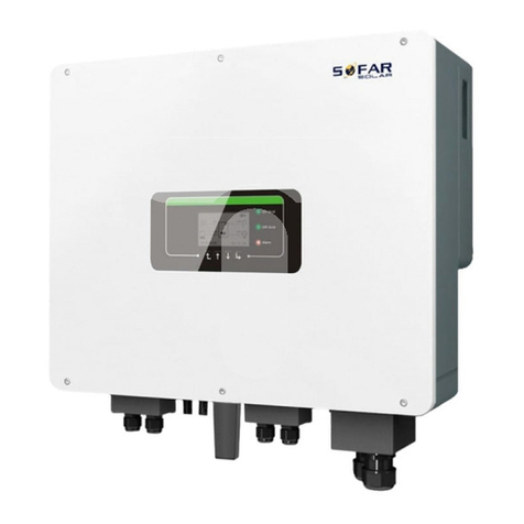
ME 5K...20KTL-3PH is an AC coupled bi-directional battery
converter. Customers can purchase batteries & ME 5K...20KTL-3PH
as an energy storage add-on to his/her existing renewable energy
system. ME 5K...20KTL-3PH helps to achieve optimal usage of
renewable energy.
The ME 5K...20KTL-3PH inverter has a variety of built-in
operating modes to suit the diverse user needs.
The ME 5K...20KTL-3PH inverter can provide a complete solution
in the period of rising energy costs such as oil and coal, the
energy subsidy of photovoltaic grid-connected system keeps
falling. In the period of continuous power supply and emergency
power supply demand in mountainous areas or base stations
without power grid.

PRODUCT FEATURES
11
3.2 Product dimensions
Front view
①
left view
②
Bracket
③

PRODUCT FEATURES
12
3.3 Labelling on the device
Labelling must not be covered or removed!
3.4 Functional features
The ME 5K...20KTL-3PH energy storage inverters allow up to 10%
overloading to maximize power output, and the Uninterruptible
Power Supply (UPS) mode can support inductive loads such as air
conditioners or refrigerators with an automatic switchover time
of less than 20 milliseconds.
3.4.1 Functions
1. Max. battery charge and discharge efficiency 97.7%.
2. 2 strings of battery input with maximum 50A charge and
discharge current.
3. Wide battery voltage range(180-800V).
4. Off-grid output can be connected to unbalanced load.
5. AC Multi-parallel function, more flexible system solution.
6. The EPS output can be connected to unbalanced loads
7. Smart monitoring, RS485/WiFi/Bluetooth.
3.4.2 Electrical block diagram

PRODUCT FEATURES
13

PRODUCT FEATURES
14
3.5 Connecting GTX 3000-H batteries (AMASS)
Using SOFARSOLAR's own battery system GTX 3000-H is a way to
build scalable battery systems. A GTX 3000H battery module has a
nominal capacity of 2,5 kWh, allowing multiple configurations
for one tower from 10 kWh (GTX 3000-H4) to 25 kWh (GTX 3000-H10),
The series battery is rated at 25A and the individual battery is
rated at 51.2V.
The ME 5 ... 8KTL-3PH models have one battery input (max.
current 25 A), and the ME 10 ... 20KTL-3PH models have two
battery inputs (max. current 25 A / 25 A).
NOTE
Configuration of the battery setup should only be done
when the inverter is in standby mode!
Advanced Settings – 9. Switch on / off – Switch Off
If a battery input is unused, ensure to set this in
the inverter's system settings, for example:

PRODUCT FEATURES
15
System Settings – Input Channel Config – Bat
Channel2 – Not Used.
The battery inputs of different inverters should not
be connected in parallel
Each battery tower corresponds to a unique battery
address. Each battery address can be configured from
00–15 or not used
The other battery parameters should be set according
to the battery specifications
3.6 Connecting BTS 5K batteries
Using SOFARSOLAR's own battery module BTS 5K is a way to build
scalable battery systems. A BTS E5-DS5 battery system has a
nominal capacity of 5 kWh, allowing multiple configurations for
one tower from 5 kWh (BTS E5-DS5) to 10 kWh (BTS E20-DS5). The
parallel battery are rated at 400V and the individual battery
are rated at 7A.
The ME 5 ... 8KTL-3PH models have one battery input (max.
current 25 A), and the ME 10 ... 20KTL-3PH models have two
battery inputs (max. current 25 A / 25 A).
This manual suits for next models
5
Table of contents
Other Sofar Inverter manuals

Sofar
Sofar HYD 6000-EP User manual

Sofar
Sofar SOFAR 3K-6KTLM-G2 User manual

Sofar
Sofar HYD 5KTL-3PH User manual
Sofar
Sofar BTS E5-DS5 User manual

Sofar
Sofar 25KTLX-G3 User manual

Sofar
Sofar DRM0 Reference manual

Sofar
Sofar HYD 3 6K-EP Series User manual

Sofar
Sofar 100KTLX-G4 User manual

Sofar
Sofar GTX5000S User manual

Sofar
Sofar CXAU0655BVS User manual

Sofar
Sofar 1100TL User manual

Sofar
Sofar 250KTL-HV User manual

Sofar
Sofar ESI 3K-S1 User manual

Sofar
Sofar 255KTL-HV User manual

Sofar
Sofar 60KTLX-G3 User manual
Sofar
Sofar 3KTLM-G2 User manual

Sofar
Sofar HYD 3000-EP User manual

Sofar
Sofar R10000TL User manual

Sofar
Sofar HYD 5KTL-3PH User manual
Sofar
Sofar 25KTLX-G3 User manual