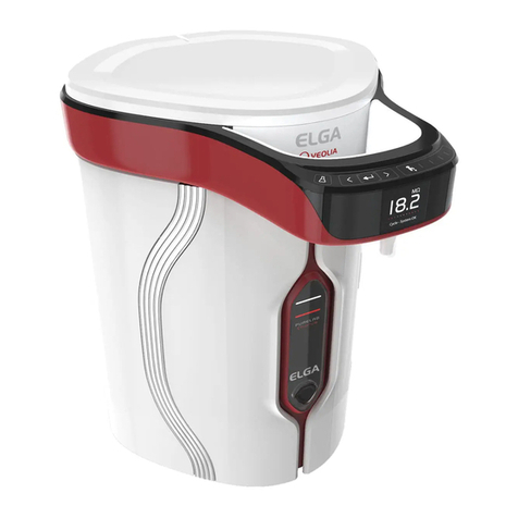
ELGA CENTRA S200 US User manual

CENTRA S200/R200 - US
Operator Manual


ELGA CENTRA - S200 US/CENTRA - R200 US Operator Manual
CENTRA - S200 US/CENTRA - R200 US Version 01 – 08/14Page i
Copyright Note
The information contained in this document is the property of VWS
(UK) Ltd. and is supplied without liability for errors or omissions.
No part of this document may be reproduced or used except as
authorized by contract or other written permission from VWS (UK)
Ltd. The copyright and all restrictions on reproduction and use
apply to all media in which this information may be placed.
VWS (UK) Ltd. pursue a policy of continual product improvement
and reserve the right to alter without notice the specification,
design, price or conditions of supply of any product or service.
ELGA LabWater is a trading name of VWS (UK) Ltd.
ELGA®is the global laboratory water brand name of Veolia Water.
ELGA®, PURELAB®, MEDICA® and CENTRA® are trademarks
of ELGA LabWater.
Minncare is a trademark of Minntech Corporation.
© VWS (UK) Ltd. 2014
All rights reserved.
Publication ref: MANU40549
Version 1 – 08/14

CENTRA - S200 US/CENTRA - R200 US Operator Manual ELGA
Page ii CENTRA - S200 US/CENTRA - R200 US Version 1 – 08/14
TABLE OF CONTENTS
1. INTRODUCTION...................................................................1
1.1 Product Range ............................................................1
1.2 Use of this Manual.......................................................1
1.3 Customer Support.......................................................1
2. HEALTH AND SAFETY NOTES ..........................................2
2.1 Electricity.....................................................................2
2.2 Pressure......................................................................2
2.3 Sanitization Chemicals................................................2
2.4 Control of Substances Hazardous to Health (COSHH)3
3. PRODUCT AND PROCESS DESCRIPTION........................4
3.1 Product Description.....................................................4
3.2 Process Description ....................................................5
3.3 Flow diagrams.............................................................7
3.4 Technical Specification................................................8
3.5 RO Permeate Flowrate vs. Temperature..................12
4. INSTALLATION INSTRUCTIONS......................................13
4.1 Unpacking the CENTRA ...........................................13
4.2 Positioning the CENTRA...........................................13
4.3 Connecting the CENTRA ..........................................15
5. CONTROLS ........................................................................19
5.1 PASSkeys .................................................................20
5.2 System Preferences..................................................20
5.3 Setting Up Replacement Timers / Reminders...........27
6. COMMISSIONING...............................................................29
6.1 Initial Start Up............................................................29
7. OPERATION .......................................................................33
7.1 Night service / Operational day.................................33
7.2 Continuous Recirculation (24/7)................................33
8. MONITORING .....................................................................34
8.1 RO fill.........................................................................34
8.2 RO fill and recirculation.............................................34
8.3 Recirculation..............................................................34
8.4 Consumable dates ....................................................34
9. MAINTENANCE..................................................................35
9.1 Replacing the Composite Vent Filter / Air Filter........35
9.2 Replacing pre-treatment filter LC159........................37
9.3 Replacing 0.2µm in line filter LC160 or CFYCZD1460
(HF only)....................................................................38
9.4 Replacement of UV lamp LC158 (CENTRA - R200 US
only)...........................................................................39
9.5 Installation / replacement of ion-exchange cylinder..40
10. SANITIZATION PROCEDURES.........................................41

ELGA CENTRA - S200 US/CENTRA - R200 US Operator Manual
CENTRA - S200 US/CENTRA - R200 US Version 01 – 08/14Page iii
10.1 Sanitization selection.................................................42
10.2 RO sanitization (Process off) ....................................42
10.3 RO sanitization (Process on) ....................................44
10.4 Recirculation sanitization ..........................................45
11. TROUBLE SHOOTING.......................................................47
12. CONSUMABLES AND ACCESSORIES ............................49
13. KEY TO CONTROL PANEL...............................................50
13.1 Alarm Conditions.......................................................52
13.2 Replacement Timers.................................................53
14. WARRANTY/CONDITIONS OF SALE ...............................54
15. USEFUL CONTACT DETAILS...........................................56


ELGA CENTRA - S200 US/CENTRA - R200 US Operator Manual
CENTRA - S200 US/CENTRA - R200 US Version 01 – 08/14Page 1
1. INTRODUCTION
1.1 Product Range
This operator manual has been prepared for the product models:
CENTRA - S200 US 115V ac 60Hz
CENTRA - S200 US 230V ac 50Hz
CENTRA - S200HFV US 230V ac 50Hz/60Hz
CENTRA - S200HFR US 230V ac 50Hz/60Hz
CENTRA - R200 US 115V ac 60Hz
CENTRA - R200 US 230V ac 50Hz
CENTRA - R200HFV US 230V ac 50Hz/60Hz
CENTRA - R200HFR US 230V ac 50Hz/60Hz
Unless stated the products will be referred to in the following
generic terms:
CENTRA - S200 US
CENTRA - R200 US
1.2 Use of this Manual
This manual contains full details on installation, commissioning and
operation of the CENTRA unit. If the instructions in this handbook
are not followed then the performance of this product and/or the
safety of the user may be compromised.
1.3 Customer Support
Service support and consumable items are available from your
local supplier or distributor. Refer to customer service contact
details shown at the end of this publication.
CENTRA - S200/R200 US

CENTRA - S200 US/CENTRA - R200 US Operator Manual ELGA
Page 2CENTRA - S200 US/CENTRA - R200 US Version 01 – 08/14
2. HEALTH AND SAFETY NOTES
CENTRA products have been designed to be intrinsically safe,
however, it is important that personnel working on these units
understand any potential dangers. All safety information detailed in
this handbook is highlighted as WARNING and CAUTION
instructions. These are used as follows:
WARNING! WARNINGS ARE GIVEN WHERE FAILING
TO OBSERVE THE INSTRUCTION COULD
RESULT IN INJURY OR DEATH TO
PERSONS.
CAUTION!
Cautions are given where failure to
observe the instruction could result in
damage to the equipment, associated
equipment and processes.
WARNING! IF THE EQUIPMENT IS
USED IN A
MANNER NOT SPECIFIED BY ELGA, T
HE
PROTECTION PROVIDED
BY THE
EQUIPMENT MAY BE IMPAIRED.
POSITION THE POWER S
UPPLY SO
THAT IT CANNOT COME
INTO CONTACT
WITH WATER
2.1 Electricity
It is essential that the electrical supply to the CENTRA is isolated
before any items are changed or maintenance work performed.
The external isolator providing power to the unit should be
positioned so that it is easily accessible by all users.
WARNING! THIS APPLIANCE MUST BE EARTHED
2.2 Pressure
The main water supply should be isolated and residual pressure
released prior to removal of any components or carrying out work
on the unit.
Switch off the process and relieve pressure in the distribution loop
by opening a point-of-use.
2.3 Sanitization Chemicals
During the sanitization cycle Minncare Cold Sterilant is used and
relevant safety guidance is included in this handbook. Please refer
to the manufacturer for material safety data sheets.
Minncare Cold Sterilant is EPA registered as a sterilant, high level
disinfectant, and sanitizer.
Spent Minncare Cold Sterilant is acidic and requires normal
neutralization as specified by your local state and local regulations.
1% of Minncare Cold Sterilant has a pH of 3.5.

ELGA CENTRA - S200 US/CENTRA - R200 US Operator Manual
CENTRA - S200 US/CENTRA - R200 US Version 01 – 08/14Page 3
2.4 Control of Substances Hazardous to Health
(COSHH)
Material safety data sheets covering the various replaceable
components which contain chemicals are available upon request.
Contact your local ELGA LabWater distributor.

CENTRA - S200 US/CENTRA - R200 US Operator Manual ELGA
Page 4CENTRA - S200 US/CENTRA - R200 US Version 01 – 08/14
3. PRODUCT AND PROCESS
DESCRIPTION
3.1 Product Description
The CENTRA range of water purification units has been
specifically designed to produce, distribute and maintain purified
water for laboratory, medical and industrial applications.
Purified water may be distributed around the installation under
pressure to single or multiple points of use.
A range of accessories is available to complement the unit (see
Section 12. - Consumables and Accessories, for detail).
CENTRA - S200/R200 US
Control Panel
PASSkey
reader
Door

ELGA CENTRA - S200 US/CENTRA - R200 US Operator Manual
CENTRA - S200 US/CENTRA - R200 US Version 01 – 08/14Page 5
3.2 Process Description
CENTRA - S200/R200 US
•Feed water enters through a control valve (V1), and
through a particulate filter (FH1) into the inlet of the RO
pump (P1). Pressure in the pipework of the pump inlet is
monitored with a pressure switch (PSW1) to ensure that
it cannot run without sufficient water.
•P1 provides sufficient pressure and flow to the RO
membrane (M1). The RO concentrate flow is controlled
through a pressure relief valve (PRV2) or concentrate
flush valve (V3).
•Upon initial start-up the system completes a concentrate
flush to remove scale and debris from the surface of the
membrane surface to ensure good RO performance is
maintained.
•RO permeate water passes through:
•Temperature sensor (TS1), which provides accurate
temperature measurement.
•Water quality sensor (QS1), which measures the
conductivity of the water.
•RO permeate water is initially flushed to drain through the
overflow device until one of the following conditions
occurs:
•Minimum flush time is completed.
•Water quality is below set alarm point.
•4 minutes permeate flush has occurred without the
permeate quality passing the alarm set point. This will
result in an alarm condition that may be cleared
automatically as the RO performance improves.
•Water enters the reservoir through permeate control
valve (V2) and fills the reservoir until full (350 liters). The
RO system will only function if the level in the reservoir is
sufficiently low, less than 240 liters.
•Upon reaching 350 liters the RO system performs a
further concentrate flush to reduce the concentrate
conductivity levels within the membrane housing and
reduce the possibilities of precipitation on the membrane
surface.
•Water from the reservoir is distributed around the
installation at pressure (6 bar maximum) by the
recirculation pump (P2), controlled via the pressure-
sustaining valve (PSV1) and monitored with a pressure
sensor (PS1), before finally returning through a spray ball
into the reservoir.
•Products fitted with a variable speed recirculation pump
(P2) use feedback from a pressure transducer (PT1) to
regulate the pump output to maintain a constant outlet
pressure (typically 4 bar). This also reduces the outlet
flow when water is not taken from the recirculation loop.

CENTRA - S200 US/CENTRA - R200 US Operator Manual ELGA
Page 6CENTRA - S200 US/CENTRA - R200 US Version 01 – 08/14
•Within the CENTRA – R200 US connections are
available to link to externally positioned cylinders
containing water purification media, to remove impurities
and maintain water purity around the system. The media
in the cylinders can be selected to meet specific
requirements.
WARNING: Any cylinders or additional equipment
installed (filters etc.) including ring-main
pipework, must be rated to the operating
pressure of the CENTRA system (6 bar
maximum).
•CENTRA - R200 US units include a UV chamber (UV1)
where purified water is exposed to intense UV radiation
to provide continuous bacterial control and to promote
the cleavage of organic molecules.
•Final filtering is provided by an absolute 0.2µm bacterial
and particulate filter. The difference in delta P between
PG1 and PG3 can be used to monitor the condition of the
filter.
•Finally the purified water passes through a:
•Temperature sensor (TS2), which provides accurate
temperature measurement.
•Water quality sensor (QS2), which measures the
resistivity of the water.
•Flow sensor (FS1) which electronically measures flow
around the system.
•Air is drawn into the reservoir when water level falls. To
maintain water purity, it is necessary to filter the air.
Water quality is maintained within the recirculation
system using a composite vent filter, which removes air-
borne contaminants such as volatile organic compounds
and carbon dioxide as well as air-borne particles and
bacteria.
•The CENTRA - S200/R200 US includes the ability to
drain the reservoir completely via V4 and sanitize the
installation semi-automatically via V8 to ensure that
bacterial levels within the installation are controlled.

ELGA CENTRA - S200 US/CENTRA - R200 US Operator Manual
CENTRA - S200 US/CENTRA - R200 US Version 01 – 08/14Page 7
3.3 Flow diagrams
CENTRA - S200 US flow diagram
CENTRA - R200 US flow diagram

CENTRA - S200 US/CENTRA - R200 US Operator Manual ELGA
Page 8CENTRA - S200 US/CENTRA - R200 US Version 01 – 08/14
3.4 Technical Specification
The Technical Specifications for the CENTRA - S200/R200 US are
as follows:
Feedwater
Source Potable tap water as detailed below.
Note: It is essential that the feedwater be suitably conditioned. Please refer to
the contaminants listed below and ensure that suitable pretreatment is included
in the installation.
If in doubt contact your local ELGA LabWater representative who will be able to
provide additional guidance and support on the pretreatment requirements for
specific water types.
Failure to comply with the minimum feedwater pretreatment recommendations
will affect the life and performance of key components within the CENTRA, and
may invalidate the warranty.
Contaminant Measure Range Pretreatment
Calcium Ca ppm as CaCO3< 250 None
> 250 Softener and/or use very low RO
recovery
Total chlorine Cl ppm < 0.1 None
0.1 to 0.5 20 inch carbon
> 0.5 Cylinder of carbon sized correctly
to obtain <0.1ppm
Silica SiO2ppm < 30 None
> 30 20 inch cartridge depth filter
and/or use very low RO recovery
**
Fouling Index FI < 10 None
10 to 20 20 inch cartridge depth filter
> 20 Backwashable media filter with a
minimum flow rate of 20l/min
Iron/manganese Fe/Mn ppm < 0.05 None
> 0.05 20 inch cartridge depth filter ***
> 0.1 Back-washable Fe filter ***
Organics TOC ppm C < 2 None
2 to 3 20 inch carbon **
> 3 Cylinder of carbon sized correctly
for TOC demand **
TEMPERATURE 1 - 40ºC (Recommended 15 - 25ºC)
FLOWRATE (maximum requirement) 20l/min (5.3USGPM)
Drain requirements (gravity fall with air gap). Maximum
during sanitization.45l/min (12USGPM)
Feedwater Pressure 4bar (60psi) maximum, 2bar (30psi) minimum.
** Increase frequency of alkaline cleaning.
*** Increase frequency of acid cleaning.
Note: For information on cleaning chemicals please
contact your local ELGA LabWater
representative.

ELGA CENTRA - S200 US/CENTRA - R200 US Operator Manual
CENTRA - S200 US/CENTRA - R200 US Version 01 – 08/14Page 9
Dimensions
CENTRA - S200 US CENTRA - R200 US
Height 1820mm (71.7") 1820mm (71.7")
Width 730mm (28.75") 730mm (28.75")
Depth 890mm (35") 890mm (35")
Supply weight 180kg (396lb) 178kg (392lb)
Operational weight 530kg (1,168lb) 527kg (1,162lb)
Installation Floor Floor
Connections
CENTRA - S200 US CENTRA - R200 US
Inlet ¾"bsp ¾"bsp
Sanitization Drain ¾"bsp ¾"bsp
Reservoir drain ¾"bsp ¾"bsp
Ion-exchange cylinder inlet Install in Distribution Loop if required. ¾"bsp
Ion-exchange cylinder outlet ¾"bsp
Ion-exchange connection pressure rating 6 bar 6 bar
Electrical Requirements
Mains input 230V ac, 50Hz
115V ac, 60Hz
System control voltage (not including pumps and UV) 24V dc
Power consumption (peak demand) 2000VA
Electrical protection rating 20amps
Noise level during production and recirculation <70dBA*
* Dependent upon pump variant

CENTRA - S200 US/CENTRA - R200 US Operator Manual ELGA
Page 10 CENTRA - S200 US/CENTRA - R200 US Version 01 – 08/14
User Interface
Display Continuous graphical quality display.
Graphical flow schematic on screen with mimic display.
Backlit display with Intuitive Icons.
Adjustable settings Date / time Adjustable
Display viewing Angle Adjustable electronically
RO permeate water quality
alarm Selectable Alarm setpoints
Product water quality unit Selectable (MΩ.cm or µS/cm)
Product water quality alarm Selectable Alarm setpoints
Product water temperature
alarm Selectable Alarm setpoints
Auto restart after power failure Selectable (On/Off)
Audible alarm Selectable (On/Off)
Night/Weekend service Selectable (On/Off)
Operational day selection Selectable (Monday (1) to Sunday (7))
Data output - manual Selectable (On/Off)
Data output - timed Selectable (On/Off)
Remote display configuration Mode address selection
Sanitization reminder Selectable (On/Off)
Indicators Pre-treated feedwater quality Conductivity
Product water quality Resistivity or conductivity
Temperature Degrees Centigrade
Recirculation Flow L/min or USG/min
System Pressure Bar or psi
UV lamp* Replacement date
Pre-treatment filter Replacement date
0.2µm in line filter Replacement date
Sanitization Sanitization date
Alarms-Audiovisual RO Permeate water quality Outside set point alarm
Permeate water temperature Outside maximum operating temperature
Purified water purity Outside set point alarm
Purified water temperature Outside set point alarm
UV lamp* Change reminder
Pre-treatment filter Change reminder
0.2µm in line filter Change reminder
Sanitization Reminder
Overflow Leak detection or hydraulic failure
Tank Level controls disconnected
Outputs RS232 Printer connection
RS485 Remote display connection
Remote process button (Optional)
Volt free contact**

ELGA CENTRA - S200 US/CENTRA - R200 US Operator Manual
CENTRA - S200 US/CENTRA - R200 US Version 01 – 08/14Page 11
Safety Features
Power fail safe
Water temperature alarm**.
Water purity alarm**.
Leak detection alarm.
Access restricted by PASSkey.
Miniature circuit breaker protection of incoming electrical supply (MCB).
Pump thermal overloads.
Low voltage control circuit - 24V dc.
Visual alarms.
Audible alarms.
Remote process button (Optional).
Optional remote display.
Optional water temperature flush
Operational Features
Restart after power interrupt.
Optional printer kit for record of operating parameters.
Optional remote display.
Product Water Specification
Voltage/freq. R/S 200 R/S 200 HFV R/S 200 HFR
Flowrate (exit from unit) - l/min (USG/min) 230/50
115/60 16 (4.2)
18 (4.8) 30 (8)
38 (10) 30 (8)
38 (10)
Distribution Loop Pressure – typical (bar) 3 3 3
Distribution Loop Pressure – maximum (bar) 6 4 4
Daily usage - typical Up to 5000L (1321USG)
Daily usage - maximum Up to 6000L (1585USG)
CENTRA - S200 US CENTRA - R200 US
Inorganic RO Permeate* Up to 18.2MΩ.cm***
TOC ppb <100* <10****
Bacteria <5CFU/ml**** <5CFU/ml****
Particles 0.2µm 0.2µm
* Feedwater dependent.
** Output to operate 24V dc relay.
*** Ion-exchange cylinder installed (Nuclear or Hypex grade).
**** System to be installed following ELGA LabWater installation
guidelines and regularly sanitized.
As part of our policy of continual improvement we reserve the right
to alter the specifications given in this document.

CENTRA - S200 US/CENTRA - R200 US Operator Manual ELGA
Page 12 CENTRA - S200 US/CENTRA - R200 US Version 01 – 08/14
3.5 RO Permeate Flowrate vs. Temperature
Nominal Permeate Flowrate vs Temperature
0
5
10
15
20
25
100 125 150 175 200 225 250
Flow (L/Hr)
Temperature (C)

ELGA CENTRA - S200 US/CENTRA - R200 US Operator Manual
CENTRA - S200 US/CENTRA - R200 US Version 01 – 08/14Page 13
4. INSTALLATION INSTRUCTIONS
WARNING! THIS UNIT IS HEAVY.
NEVER
ATTEMPT TO MOVE WITH
OUT USING
THE CORRECT LIFTING EQUIPMENT.
4.1 Unpacking the CENTRA
The following items should be supplied with your CENTRA:
1. Operator Manual.
2. Composite Vent Filter (LC156 or LC173).
3. Pre-treatment filter (LC159).
4. 0.2µm in line filter.
5. PASSkeys (SP772).
6. 2 x Filter spanners.
7. 2 x Sanitization tubes.
Note: Ion-exchange cylinders and external
pretreatment are not included with the CENTRA.
Please contact your local ELGA LabWater
representative to ensure that the correct water
treatment technologies are selected for your
application.
4.2 Positioning the CENTRA
Before installation and operation of the CENTRA unit, please read
and observe the following points.
Environment
The unit should be installed on a flat, level floor, in a
clean, dry environment.
WARNING! ENSURE THAT THE UNIT
IS
POSITIONED ON A FLOO
R CAPABLE
OF SUPP
ORTING THE MAXIMUM
WORKING LOAD OF THE UNIT.
WARNING! ADDITIONAL EQUIPMENT
SHOULD
NOT BE MOUNTED ON TOP OF
THE
CENTRA - S200/R200 US
. FAILURE TO
OBSERVE THIS INSTRUC
TION COULD
RESULT IN SERIOUS INJURY.
Note: Refer to Specifications for unit weights and
footprint size (Section 3.4 - Technical
Specification).
The unit is designed to operate safely under the following
conditions:
•Indoor Use.
•Altitude up to 2000m.
•Temperature Range 5 - 40°C.
•Maximum Relative Humidity 80% @ 31°C decreasing
linearly to 50% @ 40°C, non-condensating.

CENTRA - S200 US/CENTRA - R200 US Operator Manual ELGA
Page 14 CENTRA - S200 US/CENTRA - R200 US Version 01 – 08/14
The unit is in Installation Category II, Pollution Degree 2,
as per IEC1010-1.
Service Access
It is recommended that sufficient allowance be made for
accessing components on the rear of the product, which
may require servicing or replacement during its life in the
field.
WARNING! ONCE COMMISSIONED AN
D IN
OPERATION THE CENTRA
IS
EXTREMELY HEAVY AND
MUST NOT
BE MOVED. FAILURE TO
OBSERVE
THIS INSTRUCTION COU
LD RESULT
IN SERIOUS INJURY.
Electrical
CENTRA must be properly earthed and protected with the
correctly rated fuse or MCB.
Were possible components are operated at low DC
voltage to reduce risk of electric shock.
Some components operate at mains supply voltage and
are suitably protected within the unit.
Power should be switched off and isolated before
commencing maintenance work.
WARNING! FAILURE TO ISOLATE T
HE INCOMING
ELECTRICITY SUPPLY B
EFORE
REMOVING COVERS OR
COMMENCING MAINTENAN
CE WORK
COULD RESULT IN DEATH.
Pipework and Pipework Installation
The precise details of each installation will vary according
to the individual customer requirements.
Note: Refer to Typical installation and layout diagram
(Section 4.3 - fig. 1 and fig. 2).
If existing pipework installations are being utilized it is
recommended that Technical Support are contacted to
ensure suitability in terms of material and pressure drop,
and that correct installation and sanitization procedures
are adopted during system commissioning.
All connections to the unit are ¾"bspp female threads and
should be sealed with either PTFE tape or ‘o’ring fittings.
CAUTION!
The use of pipe sealant is not
recommended and may cause
degradation and failure of plastic
components.
All pipework should be suitable for the quality of water
being distributed and installed to manufacturer
guidelines.
CAUTION!
All pipework should have a pressure
rating exceeding the maximum
operating pressure of the installation
and suitably de-
rated for the maximum
water temperature.
This manual suits for next models
3
Table of contents
Other ELGA Laboratory Equipment manuals
ELGA
ELGA MEDICA Pro EDI User manual

ELGA
ELGA MEDICA-R 7/15 US User manual

ELGA
ELGA MEDICA-R200 - US User manual
ELGA
ELGA PURELAB 7000 - US Instruction manual

ELGA
ELGA MEDICA Pro EDI Instruction manual
ELGA
ELGA PURELAB flex 1 & 2 - US User manual

ELGA
ELGA MEDICA Pro 30 User manual

ELGA
ELGA Medica EDI 15 User manual
ELGA
ELGA PURELAB Option-Q 7/15 - US User manual
ELGA
ELGA CENTRA-R 60 US User manual
